Pololu Blog »
Pololu Blog (Page 12)
Welcome to the Pololu Blog, where we provide updates about what we and our customers are doing and thinking about. This blog used to be Pololu president Jan Malášek’s Engage Your Brain blog; you can view just those posts here.
Popular tags: community projects new products raspberry pi arduino more…
COVID-19 impact update: still hanging on after three weeks
Monday, 13 April 2020 update – we got our PPP loan!
 |
After 3 weeks of emergency operations, we are still shipping all orders!
Today, April 6, marks the beginning of our fourth week of emergency operations. We are still hanging on, and it looks like we will be able to maintain operations similar to those of the past three weeks (i.e. continue shipping all orders with a minimal staff on site) at least through the end of April, by which point I hope some of the emergency loans we have applied for might start coming in.
Today I am just posting some quick updates about frequently asked questions; please see my last two posts for more information about how we are coping with the coronavirus emergency:
- 22 March 2020 – initial COVID-19 impact update and appeal for donations after the first week of emergency operations, when I thought complete shutdown of Pololu operations was imminent.
- 29 March 2020 – update after two weeks, with a few sections:
- We are still operating, with every order shipped! – with tips on how to check stock and look for similar products on our site
- Thank you to everyone who has donated – with extra details about how donations help beyond immediate dollar value
- Landlord/building situation – detailed explanation about how we ended up in the building we are in and why we cannot expect any immediate help from the landlord
- SBA loans/stimulus package – some thoughts on emergency loans we are applying for (a little more info in today’s post)
- Outlook and plan for now – generally still applicable a week later
- How you can help
- 6 April 2020 – this post
- Thank you for your continued donations
- Please help reduce overwhelming workload
- Emergency loan updates
- Employee update
- Pictures of life at Pololu
- How you can help (mostly repeated from last week’s post)
Thank you for your continued donations 🙏
We are very grateful for the many donations that continue to come in. As we trim our expenses, those donations become a larger fraction of what we need to get by. I know it’s asking so much for donations with no strings attached, and it means a great deal at a time when we are scrambling to make ends meet. To the many of you making us special proposals and suggestions, thank you and please keep them coming. We do not have the resources now to reply to them individually, but they do affect what we are considering offering and how we continue to operate.
If you can, please consider donating to help Pololu make it. We have set up item 2400 for donating in $1 increments.
Please help reduce overwhelming workload (for those of us who can work)
We are especially grateful for any routine orders that do not require special considerations. We are also happy to help with emergency orders involving efforts to fight the pandemic. For smaller, non-emergency inquiries, please understand that we are trying to maintain most of our usual operations with a much more limited staff while having to take on a lot of extra work (new HR issues for navigating layoffs vs. waiting for possible stimulus funds, coming up with new operating/safety procedures, rerouting incoming and outgoing packages among constantly changing rules for each country and carrier, etc.). Please help us reduce our workload by cutting back on non-critical inquiries. For regular orders, prices and stock are all on the web site. Tracking numbers are included in shipment confirmation emails. Invoices are available on the website when you log in. For technical support, please consider our forum.
Emergency loan updates
 |
One of the most common questions or recommendations we get is about applying for emergency loans. We applied for an SBA economic injury disaster loan (EIDL) almost two weeks ago and followed up with the $10k advance application provided by the new CARES Act. We have been working with our bank all weekend to apply for the new Paycheck Protection Program loan, the applications for which have just started becoming available. My understanding is that the SBA is also scrambling as it is suddenly charged with processing more than 10x what they usually do over the whole year over the next several weeks. We received some confirmation about the EIDL loan being received but there’s been no visible progress on that, and in general, it’s difficult to know what to expect in terms of if, when, and how much we might be able to receive in emergency loans.
Given that uncertainty, it is especially urgent for us to cut costs where we can and to bring in whatever money we can to keep covering basic expenses. We are definitely hoping we qualify for some assistance and that it will come soon, so we are doing everything we can to keep all those applications moving forward while also trying to maintain operations independent of any guarantee of anything coming from that.
Employee update
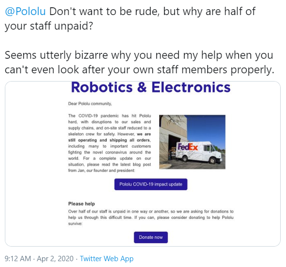 |
We received a few responses questioning our treatment of employees while asking for donations. They are far outnumbered by positive responses, and I suspect the negative responses come from people who have little appreciation of the realities of running a small business, especially amid this level of disruption. Nevertheless, I believe more people might be wondering about what we are doing, and I am proud of our response given the circumstances, so I would like to highlight what we have done so far.
Some of the responses questioned the “over half of our staff is unpaid in one way or another” phrasing. We had about 75 employees at the beginning of March, and over half of them are now either laid off, on unpaid leave, or volunteering to take a pay cut. This is just a basic reality of payroll being by far our biggest expense, and if people cannot come in to work and money stops coming in, there is nothing to pay them from. We are doing everything we can to keep Pololu in a viable state so that there is something for everyone to come back to in a few weeks or months.
Here is some of the rest of our response:
- Prior to any Nevada mandates, we began staggering our workbenches, improving sanitizing procedures, and set up some employees for working remotely.
- Within the first day of the Nevada governor’s emergency business closure declaration, we set up an emergency forum for all employees to be able to communicate without being on site. I have been posting there almost daily to keep everyone in the loop on our operations and outlook.
- We contacted all employees to make sure we had their contact information and understood their preferences about working (different people have different preferences based on their living arrangements, risk factors for COVID-19, etc.).
- We are maintaining health insurance and similar benefits for everyone who had them, including paying the employees’ portion for those who could not work and were out of paid time off (PTO). Some employees who were scheduled to begin getting coverage through Pololu are still getting added to our plans.
- We paid out remaining PTO to those laid off.
- We are maintaining PTO for those on unpaid leave and those still working.
- We paid full amounts due to those still able to work (excluding those volunteering for pay cuts).
- We are continuing safety assessments for on-site operations, including providing face masks for all on-site staff.
- We are working on improving remote connection and work capability.
Pictures of life at Pololu
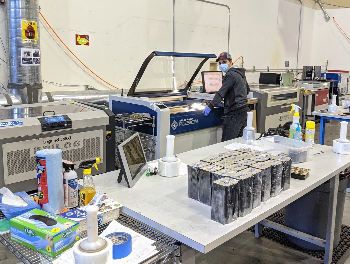 |
Pololu laser cutting department on 6 April 2020. |
|---|
 |
Pololu laser cutting department on 6 April 2020. |
|---|
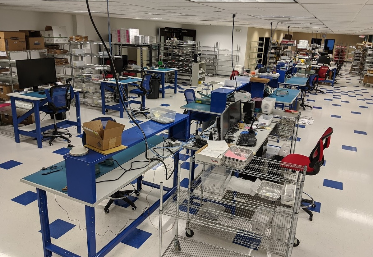
 |
Pololu packaging department on 6 April 2020. |
|---|
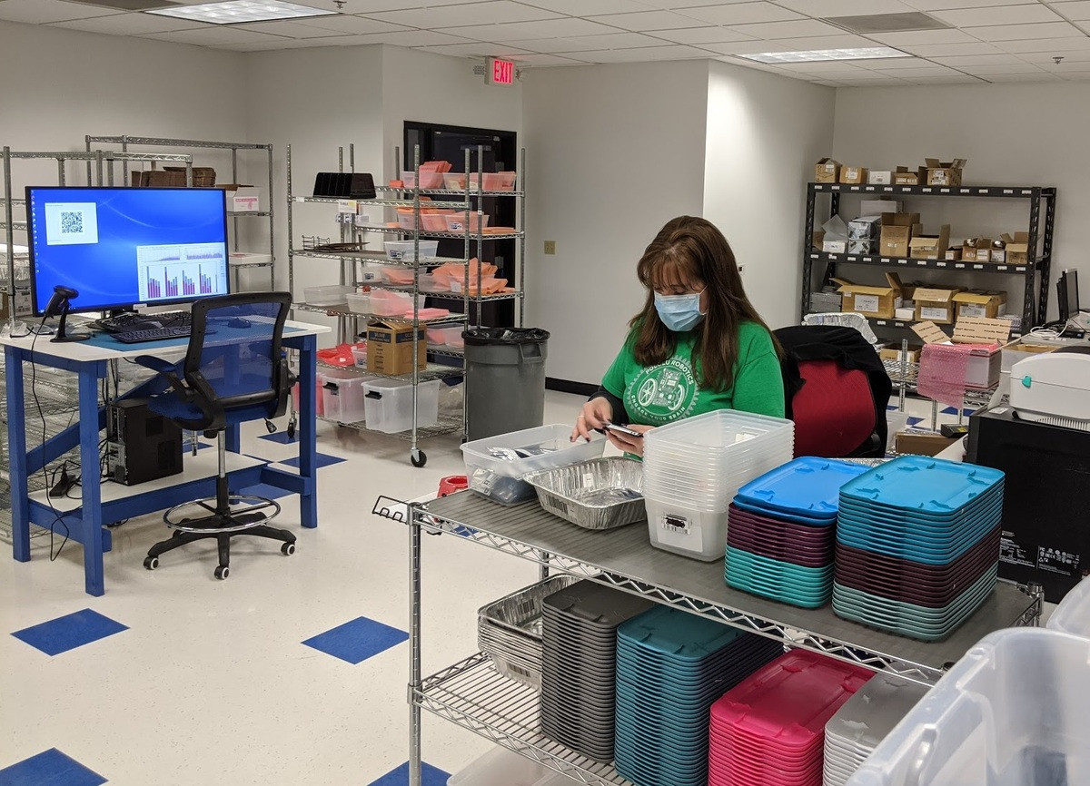 |
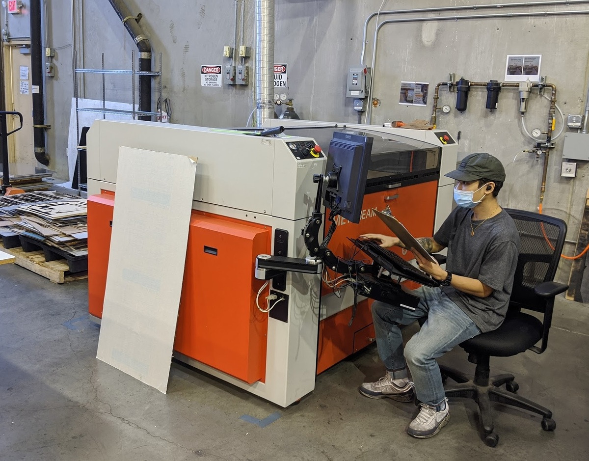
Pololu quality control on 6 April 2020. |
|---|
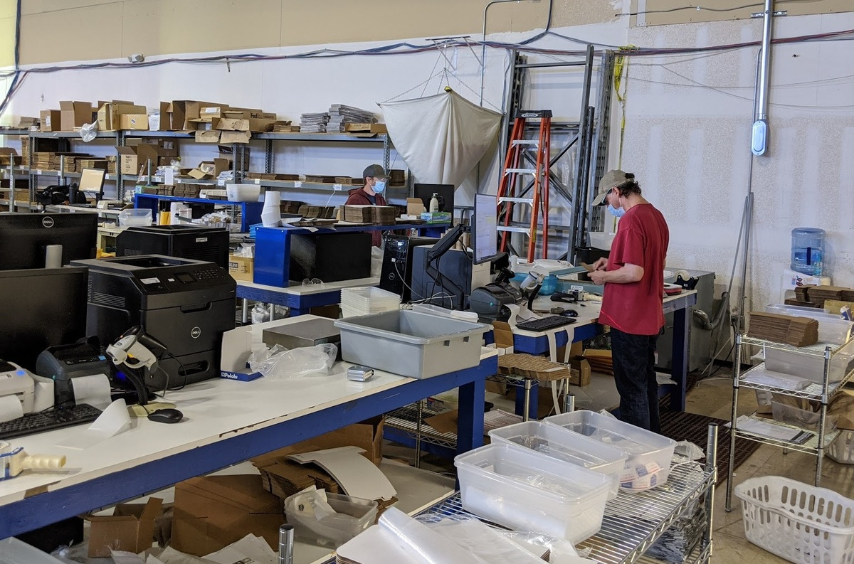 |
Pololu shipping department on 6 April 2020. |
|---|
 |
Pololu SMT pick and place production line on 6 April 2020. |
|---|
|
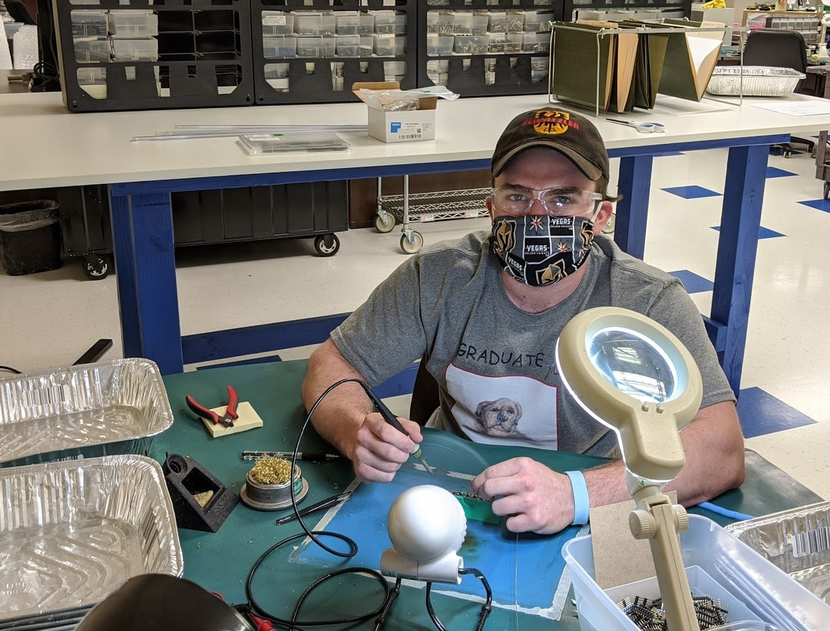
Soldering at Pololu on 6 April 2020. |
|---|
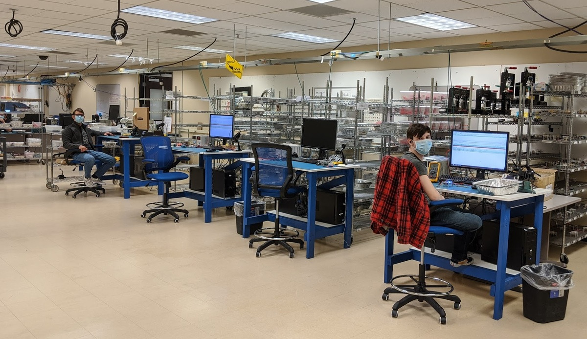 |
Pololu testing department on 6 April 2020. |
|---|
How you can help
Make a donation
If you can, please consider donating to help Pololu make it. We have set up item 2400 for donating in $1 increments.
Pay now, ship later
We have added a feature to our online checkout system to allow for orders to be placed with a “pay now, ship later” option that lets you authorize us to charge the payment for an order as soon as it comes in, possibly well ahead of when the order would actually ship. We started working on this feature at a time when we thought complete shutdown of our operations was imminent, when it might have been weeks or even months before we could reopen. As I wrote at the top of this update, we have been able to ship all orders, and I expect to continue shipping, but this option still allows us to prioritize shipments and reduce stress with orders that come in later in the day and can get shipped the next day. We have already received dozens of orders with this option selected, and it is also encouraging just to see that our customers are trying to help us out. Thank you to all of you who have selected that option!
Order non-soldered versions of products, or the higher-stock versions
We offer a few of our products with some of the optional (but usually used) through-hole connectors soldered in. If you are able to solder, please consider ordering the non-soldered versions if there is plentiful stock of them. We do all of the through-hole soldering by hand, and most of our manual assemblers were older or otherwise in the higher-risk population for COVID-19, so they are not currently working here. And if you’re at home doing a non-critical project, now is a good time to do a little extra soldering, right?
On a related note, it’s a little bit easier for us if you order the item that has more stock. Each product page has links to relevant parametric comparison tables that can help you identify similar products that might have more available stock:
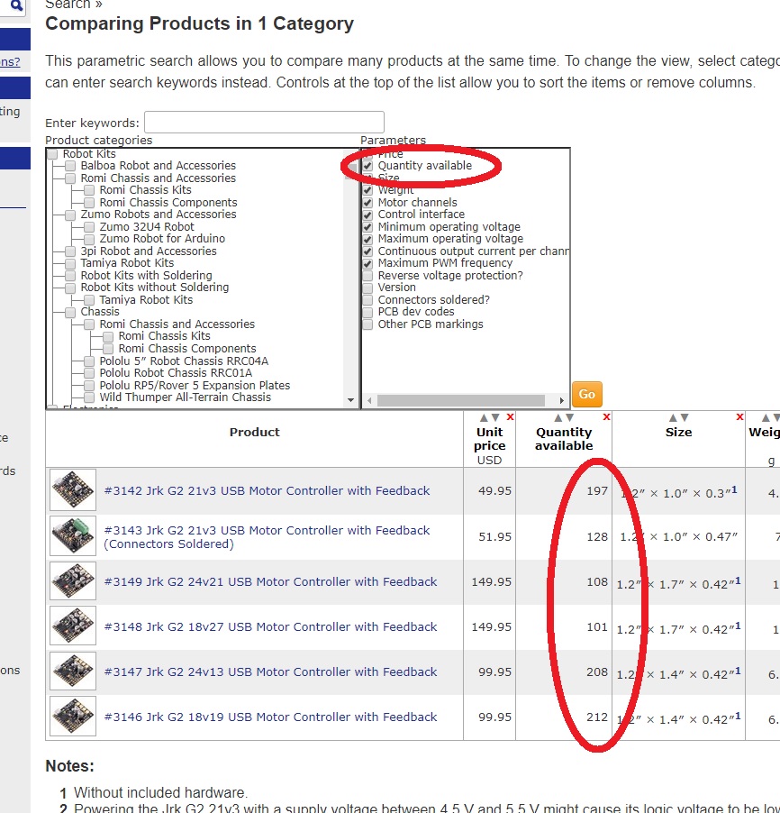 |
You can check available quantity of similar products on the parametric comparison table. |
|---|
If your application could get by with either an item of which we have 300 in stock or one of which we have 12 units, please get the product that we have much more of. It’s probably a more popular version that we make more often, and it keeps the less popular version available for those who might really need it.
Help each other on our forum
We have had to severely cut back on our technical support. If you are one those people with extra time on your hands now and are familiar with any of our products, please consider helping out our other customers on our forum.
Ask others to help us out
If you know anybody that could afford to help us out, please let them know and ask them to contribute.
Other suggestions and ideas
Part of the reason I have been going into more details in some areas of these updates is so you might be able to better give us advice about how we could make things better. Maybe you’re also working at a small business facing similar challenges, and you have some good suggestions. Maybe your uncle has a vacant building nearby. One suggestion I’ve heard repeatedly is about gift certificates, which we are looking into; if you know of particularly good ways of implementing that or things to be careful about, please let us know.
Thank you all for your support. Stay safe and healthy, everybody!
Monday, 13 April 2020 update – we got our PPP loan!
Related products

Coronavirus impact update: still shipping all orders
Quick summary: Pololu has filled all orders and continues to operate, including shipping products to important customers fighting COVID-19 around the world. Thank you for all of your help and donations, which are really making a difference. We are preparing for extended operations under emergency conditions and evaluating all available avenues for support. Cash donations remain the most useful and immediate way to help, but there are other ways you can help us. Donate here.
Please see new update posted Monday, 6 April 2020.
 |
Still shipping, 30 March 2020. |
|---|
It has been a week since I posted about Pololu’s dire circumstances brought about by the new coronavirus pandemic. My outlook today is much more positive than it was back then, in large part thanks to the support we have received during the past week. We are by no means out of the woods yet, as a company, as a country, and as a planet. I write today’s post to provide an update on how we are doing, to try to address the questions I am getting repeated from many people, to share our general outlook for moving forward, and to renew my appeal for help in any way possible. Since there are many topics that might be of varying degrees of interest to each of you, I will try to organize this with more sections and headings:
- We are still operating, with every order shipped!
- Thank you to everyone who has donated
- Updates about common questions
- Outlook and plan for now
- How you can help
We are still operating and have shipped every order!
We have operated for eight business days now with a skeleton crew of approximately 20 staff members on site and 10-20 more people assisting via remote connections from home. We have shipped every order for in-stock items that has been placed during that time, and we have limited production capacity for special orders beyond what is in stock.
We have had no new local business shutdown orders that would affect us since Friday the 20th, and we have received dozens if not hundreds of customer requests and certifications from customers that have been declared essential businesses or services within their jurisdictions, and as suppliers to those organizations, we are essential by extension as well. We also continue to get many confirmations of our products and services (e.g. laser cutting) being used directly in the response to the COVID-19 pandemic, so we will keep shipping orders as long as delivery services keep operating.
You can see available stock for each product live on our website, and if your order consists of just in-stock items, we should be able to ship your order within a day.
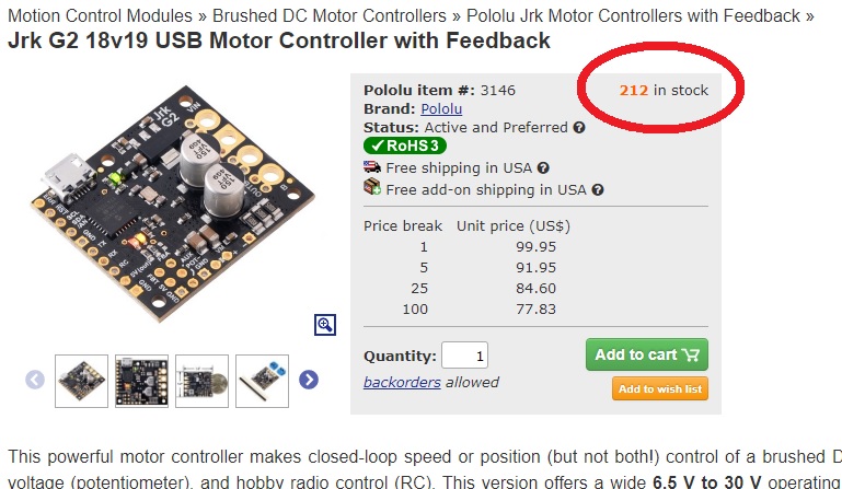 |
Available stock is shown on each product page. |
|---|
Each product page has links to relevant parametric comparison tables that can help you identify similar products that might have more available stock:
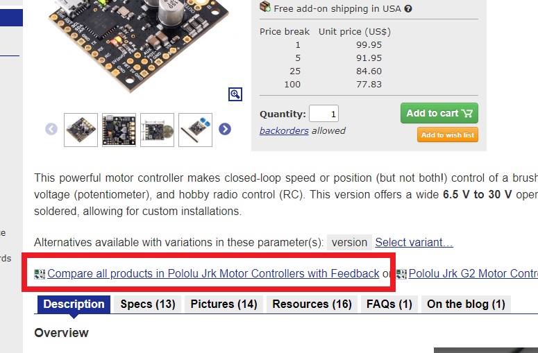 |
Each product page has links to relevant parametric comparison tables. |
|---|
|
You can check available quantity of similar products on the parametric comparison table. |
|---|
Our China facility in Shenzhen is also partially operational, and we are able to ship some special volume orders directly from there. The available shipping carriers and destinations are changing day by day as countries respond to the pandemic, but we are working with customers to route critical orders as quickly as possible. Please note that all of our electronics products are manufactured at our Las Vegas, Nevada, USA facility, so shipments directly from China are only available for select products, mostly motors and other mechanical components that we have machined or injection molded there.
We also have hundreds of distributors around the world that might be operational and have stock closer to you. We will be working with them in the coming days to update the distributors page with information about those businesses confirmed to still be in operation.
Thank you to everyone who has donated!
We have received thousands of dollars in donations since my original post. I have tried to send at least a few personal thank you emails every day, but there have been more donations than I can keep up with. It is extremely motivating to see the breadth of donations we are receiving from all over the world, from customers we haven’t heard from in a long time, to family members of employees, to former employees, to people that, as far as we can tell, have had no previous association with Pololu. To all of you whom I have not thanked yet individually, thank you!!! I am making sure everyone at Pololu knows about your support. The value of the money we receive in donations is multiplied both by the psychological boost it gives us and by getting factored into various lines of credit that we have available to us that are automatically calculated based on the rolling average revenue appearing in our accounts.
Several Pololu employees who are part of our continuing operations have volunteered reductions in their own pay so that we might conserve our limited cash on hand and continue payments and insurance for those employees that are most in need. PT from Adafruit also responded to my call for help and gave me some useful perspective and helped spread the word about our situation even as Adafruit conducted its own emergency operations out of New York, the US epicenter of the coronavirus outbreak.
The donations and support are all the more meaningful at a time like this, where nearly everyone is impacted and the future so uncertain.
If you can, please consider donating to help Pololu make it through this difficult time. You can use item 2400 to donate in $1 increments. I will also post other ways you can help us at the end of this update.
Updates about common questions
Landlord and building situation
After payroll, the building rent is our biggest expense and obligation, so I of course reached out to my landlord right away to see what their position was. Unfortunately, the building we are in was just sold in the last 6 months, so we do not have the long working history we had with the previous landlord. I am posting a little more detail here than I would normally be comfortable with, but we are in an extraordinary emergency and I am hearing the same questions and suggestions from multiple people, so I want to share this information because I believe it could be useful in getting us help and advice.
 |
We are the only tenant in a building that is approximately 86,000 square feet. The building had been vacant, I think for years, after the previous economic downturn, and we moved in here at the end of 2011, taking part of the first floor. In 2013, the landlord received an offer for the second floor. It was a time when we were growing rapidly, and the building was not at all well set up for sharing with multiple tenants, so we made the owner an offer for the space and reached an agreement that was expensive but affordable for us and at a lower rate for the landlord than the competing offer but without the need to do any new construction. Over the next several years, we agreed to extensions in the lease and a gradual takeover of the remainder of the first floor, so that we would officially have the building to ourselves and the landlord could stop looking for other tenants to fill the remaining space.
In 2018, we negotiated a new extension of the lease. The building was still in its as-is state from 2009 or whenever the previous tenants moved out, and it was a particularly impractical floorplan based on the previous tenant’s operations. The landlord preferred putting some money into renovating the space and increasing our rent over keeping the rent at a bare minimum, and so even though our cost went up again, we were getting a more usable space with plenty of room for growth at still a decent total cost. The renovations took longer than expected and ran through most of 2019. Some kind of family change caused the landlord to unexpectedly have to sell the building, which got us to where we are today: with a new owner, in a building that is bigger than we need but well set up for us, and with what I think is a pretty good rate.
The new landlord thinks it’s an incredibly good rate and thinks the market rate (of course before this pandemic hit) should be closer to double what we are paying now. We have more than four more years left on our lease, and from his perspective, he might even prefer us to be out of the building. I suspect he has dozens or even more tenants from all over suddenly asking for reductions or notifying him that they won’t be able to make rent, and given his view of what we are paying relative to what the space is worth, we are going to be low on the list of tenants he wants to make special exceptions for. So for now, if we believe we can be back to full operation in the next few months and then resume the growth path we were on, it is very important for us not to give the landlord any pretext for evicting us. I realize some of what he told me might be for negotiation, but I believe he was generally up-front with me. (And I’ve been using the singular “owner” or “landlord” or “he” for the landlord in both the current and previous landlord cases, but really I am talking about my contacts for the ownership groups.)
I related the history of how we got here so that people who know more about this kind of thing might be able to give me better advice and so that people who look at some of the pictures I am posting don’t feel that we are wasting money on an extravagant work space. Yes, we could fit our current operations into a 50,000 square foot space. But building rent agreements can be quite long-term, and with the amount we have invested in equipment and improvements here, moving would be very expensive, even if we could find an appropriate space. And the value of our contract depends a lot on how things play out. If there is a long-term depression that we cannot survive, the contract is an anchor that will drag us down and potentially finish us. If things get better relatively quickly, the contract protects us and gives us stability, letting us operate at a relatively good rate, without having to interrupt everything to move.
I should also make sure it’s clear that I completely understand my landlord’s perspective (who of course has his own mortgages and employees to keep paying), and it’s good to know that he’s open to arrangements that could be mutually beneficial. Perhaps some more spaces will open up as other businesses close, and if we get forced to stop operating for an extended period of time, that interruption might also be a good time to move. For the time being, though, I think we just need to hang on for a few months, and if that is the case, we have to keep paying the full rent.
Stimulus bill and SBA disaster loan
After days of trying on the overloaded SBA disaster loan website, we got our loan application submitted at 2:30AM on Tuesday. It’s not clear how long it will be before there is some progress with that or how much assistance we would qualify for.
We are also paying attention to the new stimulus bill that was just passed to see how it might apply to us. So far, it looks like it will be at least a few more weeks before the details get worked out to a level that we can do something with. The initial impression I am getting is that the way the support is structured, we might be incentivized to do things that would be bad for us if the support doesn’t pan out. For example, it is paramount for us to cut back on expenditures so that we have some cash to pay the most critical bills as long as possible. That includes laying off non-essential staff right away. Yet that might reduce or even eliminate some of the support we might qualify for.
There’s also a huge difference between getting a loan and that loan being forgiven. If the model for our collective response to the pandemic is that the government orders us to pause operations, then gives me money to distribute to my employees, I am happy to do my part in that arrangement. If, on the other hand, the proposal amounts to me personally being on the hook for the rest of my life to pay back a loan I took just to pay people that weren’t allowed to work, that’s not actually helping, and it would make more sense for those employees to just get paid directly from the unemployment aspects of the support bill.
We might also be facing a situation where the new support measures might encourage people who could be working to stay home and collect unemployment instead. So far, we have gotten by without pushing anyone who does not want to be here to be here. This will be a challenge for society in general as we all try to pause and then recover in this unprecedented situation. Many individuals want to work, but it might be better for the community if they don’t, and in compensating them for preventing them from working, we might be discouraging other people whom we do need to be working.
Outlook and plan for now
The past two weeks of operation have made me optimistic that we could keep operating as we have for at least several more months. This past week was especially good because we had relative stability in how we operated, and it allowed us to spend a little time on getting ahead and start preparing for operating under these emergency measures for an extended period. A few engineers who had been working on production processes and were out the first week came in and started assessing our workflow with new distancing and isolation considerations. Having a lot of space is coming in handy, at least in terms of making it easier for people to work far apart from each other. We gathered in the same room once during the whole time, to select permanent spots in the break room:
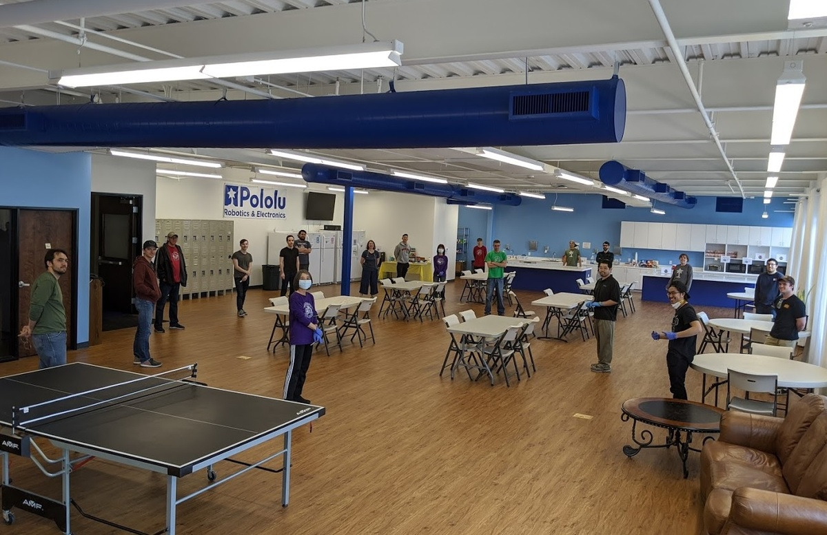 |
Pololu skeleton crew permanent table assignment meeting, March 2020. |
|---|
(Those who have individual offices are encouraged to eat there, but in general, those are the people who are already home and connected remotely.)
We are also working on improving remote connection and working options where possible, including getting more computers and monitors to employees’ homes.
With the outlook unclear on how much government support we might get and when, it’s clear we need to transition to an operating mode where we can be largely self-sufficient financially without burning out before we get there. Here, the donations we have received have been tremendously helpful in buying us time to get back on our feet.
If you can, please consider donating to help Pololu make it. We have set up item 2400 for donating in $1 increments.
Other ways you can help
Pay now, ship later
In the past week, we added a feature to our online checkout system to allow for orders to be placed with a “pay now, ship later” option that lets you authorize us to charge the payment for an order as soon as it comes in, possibly well ahead of when the order would actually ship. We started working on this feature at a time when we thought complete shutdown of our operations was imminent, when it might have been weeks or even months before we could reopen. As I wrote at the top of this update, we have been able to ship all orders, and I expect to continue shipping, but this option still allows us to prioritize shipments and reduce stress with orders that come in later in the day and can get shipped the next day. We have already received dozens of orders with this option selected, and it is also encouraging just to see that our customers are trying to help us out. Thank you to all of you who have selected that option!
Order non-soldered versions of products, or the higher-stock versions
We offer a few of our products with some of the optional (but usually used) through-hole connectors soldered in. If you are able to solder, please consider ordering the non-soldered versions if there is plentiful stock of them. We do all of the through-hole soldering by hand, and most of our manual assemblers were older or otherwise in the higher-risk population for COVID-19, so they are not currently working here. And if you’re at home doing a non-critical project, now is a good time to do a little extra soldering, right?
On a related note, it’s a little bit easier for us if you order the item that has more stock. Going back to the screenshot I have at the beginning of this post, it’s easy to see our stock levels of similar products:
|
You can check available quantity of similar products on the parametric comparison table. |
|---|
If your application could get by with either an item of which we have 300 in stock or one of which we have 12 units, please get the product that we have much more of. It’s probably a more popular version that we make more often, and it keeps the less popular version available for those who might really need it.
Help each other on our forum
We have had to severely cut back on our technical support. If you are one those people with extra time on your hands now and are familiar with any of our products, please consider helping out our other customers on our forum.
Ask others to help us out
If you know anybody that could afford to help us out, please let them know and ask them to contribute.
Other suggestions and ideas
Part of the reason I went into more details in some areas is so you might be able to better give us advice about how we could make things better. Maybe you’re also working at a small business facing similar challenges, and you have some good suggestions. Maybe your uncle has a vacant building nearby. One suggestion I’ve heard repeatedly is about gift certificates, which we are looking into; if you know of particularly good ways of implementing that or things to be careful about, please let us know.
Thank you all for your support. Stay safe and healthy, everybody!
Please see new update posted Monday, 6 April 2020.
Related products
Coronavirus update - please help Pololu survive
TL;DR: Pololu is hurting. Skeleton crew is shipping important products to customers fighting COVID-19 around the world. Most employees facing layoffs. Please donate to help us keep operating and spread the word. Donate here.
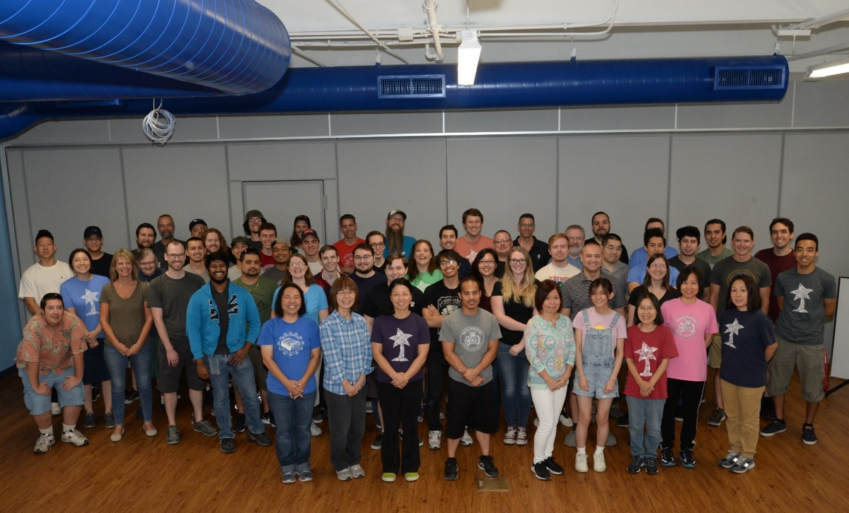 |
Impromptu picture of most of the company from August 2019, when it was still safe for this many people to gather. |
|---|
Please see new update posted Sunday, 29 March 2020.
The last time I posted on this blog was in November 2018, sixteen months ago. We have been very busy at Pololu since then, and there is so much good and positive to share about what we did in 2019 and so far in 2020. Unfortunately, what is compelling me to post this update and plea for help is the COVID-19 coronavirus pandemic that is engulfing our planet.
Nevada, where we are located, was one of the earlier states to mandate sweeping reductions in activity, with the governor announcing on the night of Tuesday, March 17, that all nonessential businesses statewide were to shut down starting on Wednesday. We immediately began contacting all of our employees on Tuesday night not to come in the next morning while trying to plan for a shutdown of operations and looking for clarity about the extent to which the order applied to a company like Pololu. On Wednesday through Friday, we operated with a skeleton crew of around twenty of us, making sure we got orders out and received important incoming shipments.
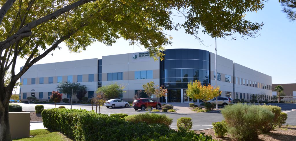
Pololu is probably not the kind of company that first comes to mind when you think of Las Vegas. We design, make, and sell thousands of products from our location just a few miles from the famous Strip. Here is our building when I was locking up Friday night, with the light from the Luxor pyramid lighting up the clouds:
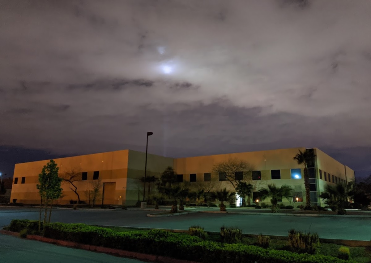 |
Pololu building exterior on the night of Friday, 20 March 2020. |
|---|
Inside, we have millions of dollars of equipment on which we have made millions of electronics boards that we have shipped all over the world. This is the newest of our three electronics production lines that we just finished setting up earlier this year, with machines that were all installed in 2018 and 2019:
 |
Pololu’s newest SMT production line, March 2020. |
|---|
We have around two dozen pieces of big equipment, each one of which was a substantial undertaking just to install, with the electrical work alone costing tens of thousands of dollars in the most demanding cases. Here is the delivery of our latest laser cutter in November:
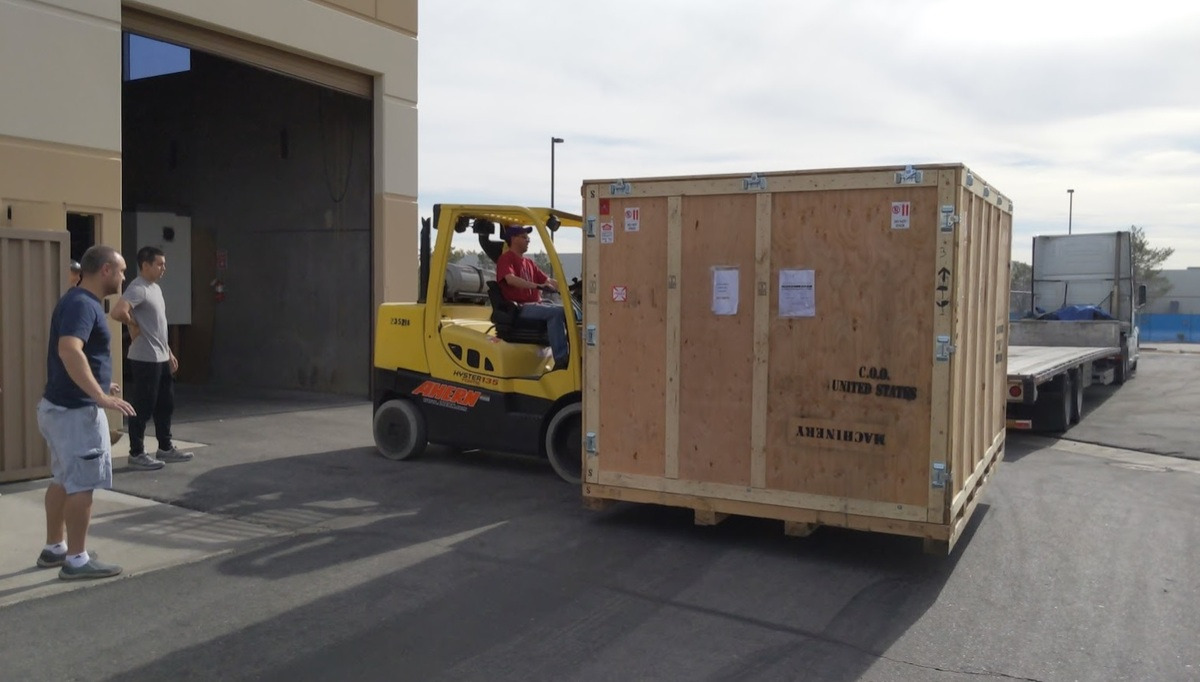 |
LaserCube delivery November 2019. |
|---|
We finally completed installation last month, and here is a picture I took for fun three weeks ago, with our first laser cutter from 2003 inside the new one:
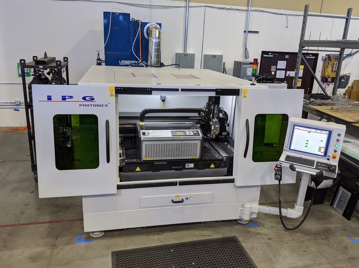 |
Pololu’s first laser cutter from 2003 inside the newest one, March 2020. |
|---|
I post these pictures to help illustrate that an operation like ours takes a huge amount of effort to build up. I’ve been working on it for twenty years, and there are about 75 more people working on it with me now. We make and ship physical things, so we can’t just do this over a remote computer connection.
 |
And what do we make? For the most part, we make components, like motor controllers and sensors, that go into bigger systems. We do not know most of the applications our products go into, and we cannot disclose some of the more intriguing ones that we do know about. But we have specific confirmation that our products are being used around the world in this fight against the new coronavirus, from components in prototypes for ventilators to components in PCR equipment, including ones used for coronavirus testing.
Are we essential, or essential enough to keep operating? With the changes we had already implemented prior to the governor’s order (for example, we suspended order pick-ups, so we are not open to the public), it seems clear that we are legally allowed to operate in accord with the clarifications the government has been issuing since Friday. Even before the ordered closures, we had done things like stagger our production work benches and spread out the tables in the break room:
 |
Staggered workbenches in production area, March 2020. |
|---|
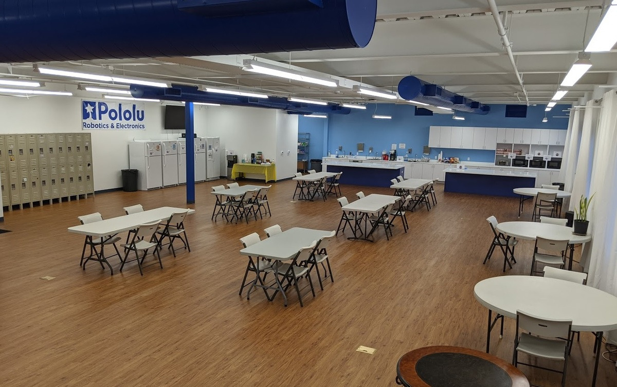 |
Spread out tables in break room, March 2020. |
|---|
(FYI several groups of our employees live and carpool together, so a few chairs at one table seemed ok to have as an option. We’re probably going to spread out chairs more and go to one assigned table per employee tomorrow.)
We are scrambling to stay in operation and to do it as safely and ethically as possible. The strain of trying to run this size of operation with two dozen people is enormous, especially while constantly having to prepare for being shut down externally and dealing with more and more uncertainties about components we need arriving. We are trying to get more people set up to work remotely, but I am posting these pictures to try to show how we cannot just run with remote workers. We are prioritizing shipping what was already made and making priority products that we know are for especially important customers.
I don’t know how much longer we will be able to run. Maybe a few more days? Perhaps even fewer of us can get some especially critical orders out for longer, as long as the shipping companies keep shipping our packages. Things keep changing, so it’s hard to say. But if we are not shipping orders, or just a small fraction of the usual ones, money won’t be coming in. I have told my employees that they should not count on another paycheck beyond the one they just got on Friday. We will keep paying for health insurance for everyone as long as we can, and we are looking into the ramifications that would have for things like unemployment insurance.
There is no way we can survive a shutdown of many weeks or even months. We tried to have redundancies in our operations, with as many backups as reasonable. We even have two compressors that we alternate each week, so that all our machines are not crippled if one of the compressors has an issue:
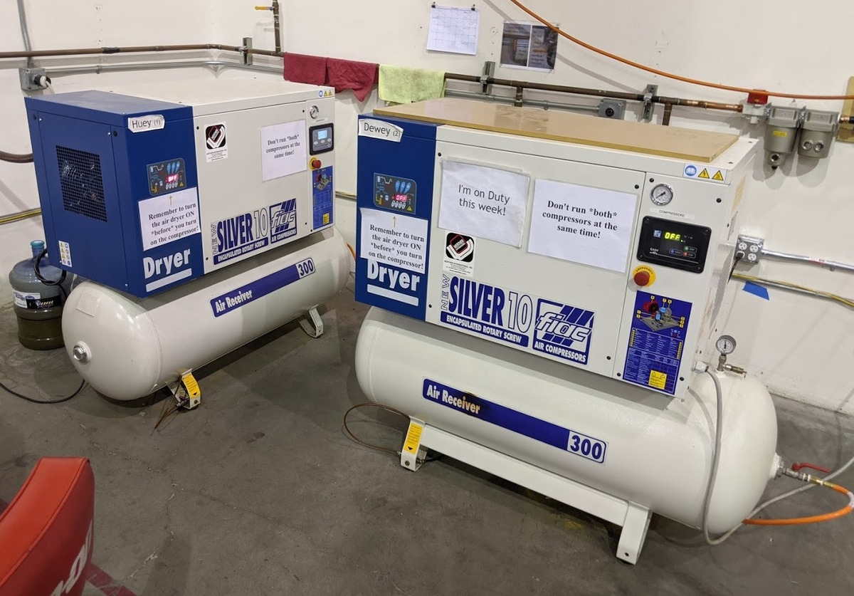 |
We alternate which compressor runs every week. |
|---|
But we just are not prepared for the level of shutdown we are facing. And so here I am, writing this post on Sunday night after coming up with a plan for tomorrow for my employees and writing to my landlord for help, begging anyone who reads this to help. I know many people and small businesses everywhere are hurting now. I am sure everyone who has put their life into their business feels like theirs is special. We have the facility and the machines and the people who know how to churn out millions of units of hundreds of designs that people around the world use. We have an awesome team. We just need the money to survive until we can start running again.
 |
Pololu executive meeting Sunday morning, 22 March 2020. |
|---|
We are of course looking everywhere for help, and will be applying for whatever disaster relief is available as it becomes available. This is an unprecedented time for us, as I know it is for everyone. I know it is so much to ask for money with no strings attached, especially at a time like this, but that is what will most let us pay our obligations and our employees without diverting resources into extra accounting and agreements. We have set up an emergency product on our website that will allow anyone to donate money to Pololu.
You can use item 2400 to donate in $1 increments. This is still part of our regular website, so checkout will ask you for a shipping address, but there is now a “no shipment” option on the next step of checkout. We’ll work on making it smoother.
If you cannot personally donate, perhaps you know of someone who could. Maybe it’s someone who likes making things and wants to support a company like Pololu. Maybe it’s someone in Nevada who knows nothing about robotics but would like to support diversification of our economy. I threw this post together quickly and marketing was never my strong suit, but I will be updating our pages with more information about why Pololu is especially worthy of your support.
We (the off-site portion of the team!) will also be working on a feature to let you order non-critical items that we would ship once we can resume operations but with permission to charge your credit cards immediately so that we can keep our employees paid. (Update 3/25/20: This feature is now available. You can find the option during step 3 of checkout.)
If you got this far, thank you for your consideration and for any help you can give. Stay safe and try to be kind and useful to those around you.
Please see new update posted Sunday, 29 March 2020.
Related products
Empty Vessels: a performance of robots, cellos, and artificial intelligence
Artist David Gardener contacted us recently to share his work, Empty Vessels (seen in the above video), an immersive audio visual installation that explores the connection between machines, data, and their environment. The piece features three cellos played by custom built robotic structures that perform music composed in real time. It premiered in November 2019 at the Society for Arts and Technology in Montreal, where it performed for sold out audiences for two weeks! David was kind enough to answer our questions about the piece and allow us to share his answers along with some more footage and pictures with you below:
 |
How long did you work on the piece?
The project started as an idea by myself (David Gardener) and Greg Debicki about a year ago. It remained an idea for most of the year until we were approached by the Society for Arts and Technology in Montreal (SAT) for help funding the project, where we could work on the project as artists in residence. At the end of the residency (in November) we would also premiere the show. This gave the project a very fast timeline taking just two and a half months from concept to presentation for two weeks of shows. I think it is probably the quickest timeline I have ever worked to, having to design, engineer & build the whole project.
Can you tell us which products of ours you used and how they were used in your project?
For the project I used the following components from Pololu:
- 12 x 9.7:1 Metal Gearmotor 25Dx63L mm HP 12V with 48 CPR Encoder (one for each string on each cello)
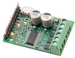
- 6 x RoboClaw 2x7A Motor Controller (two per cello to drive those motors)
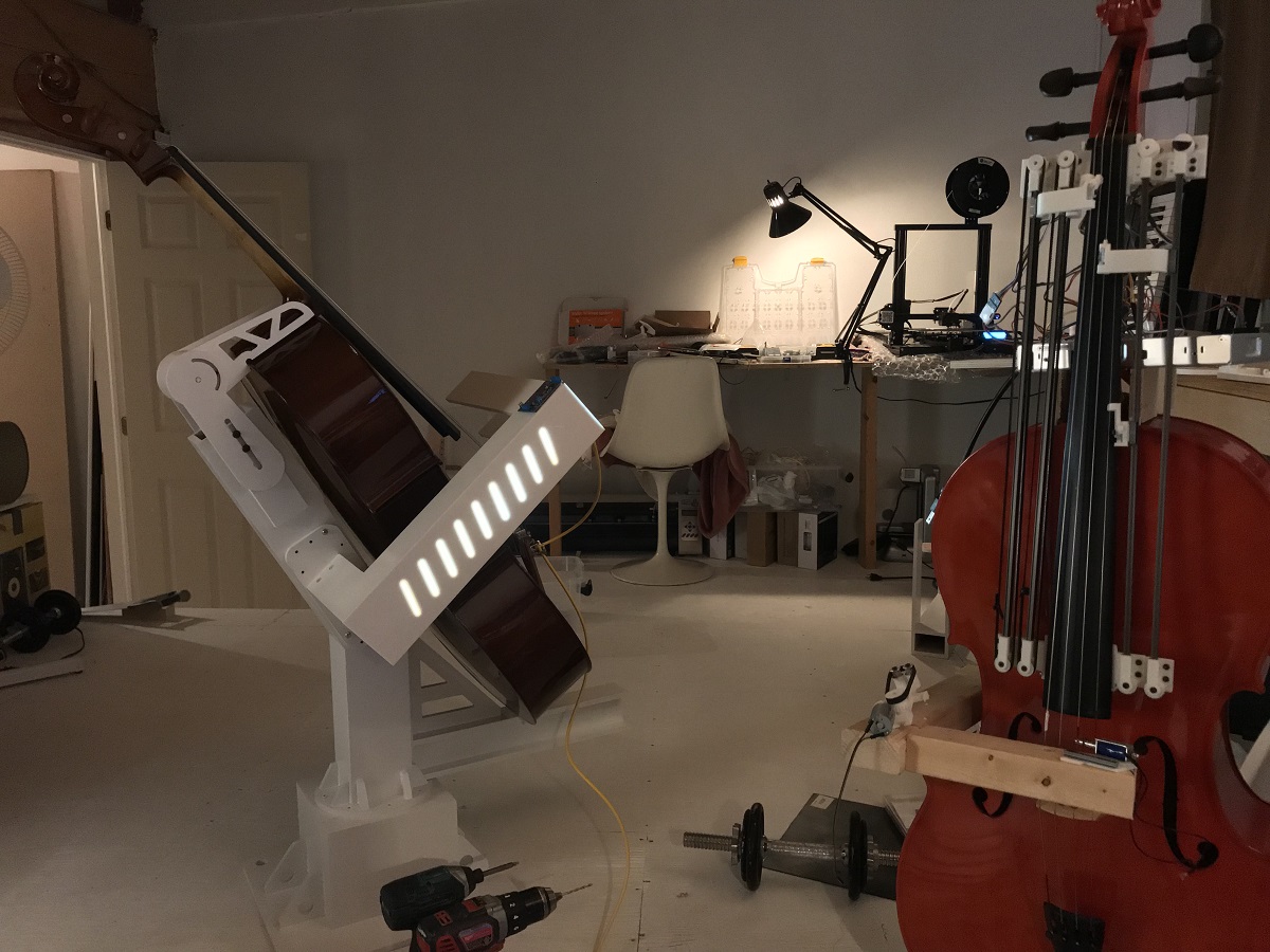
These were used to drive linear slides that moved the note sliders up and down the fingerboard. The reason for using this method was because I am a cellist myself, and the ability to slide between notes is really important in the sound of the cello. Unlike a guitar, there are no frets on a cello’s fingerboard, so the note sliders have to move to very accurate positions on the fingerboard to make sure that the notes are nicely in tune. On startup the motors would all drive the sliders to a home position using a limit switch. From there they would move to the different notes just by driving the motors to pre-defined positions. I decided to use a slider per string on each cello to maximise the amount of notes that could be played simultaneously, meaning they could play 12 note chords, or fast melody lines by splitting the melody across the 3 cellos.
|
|
|
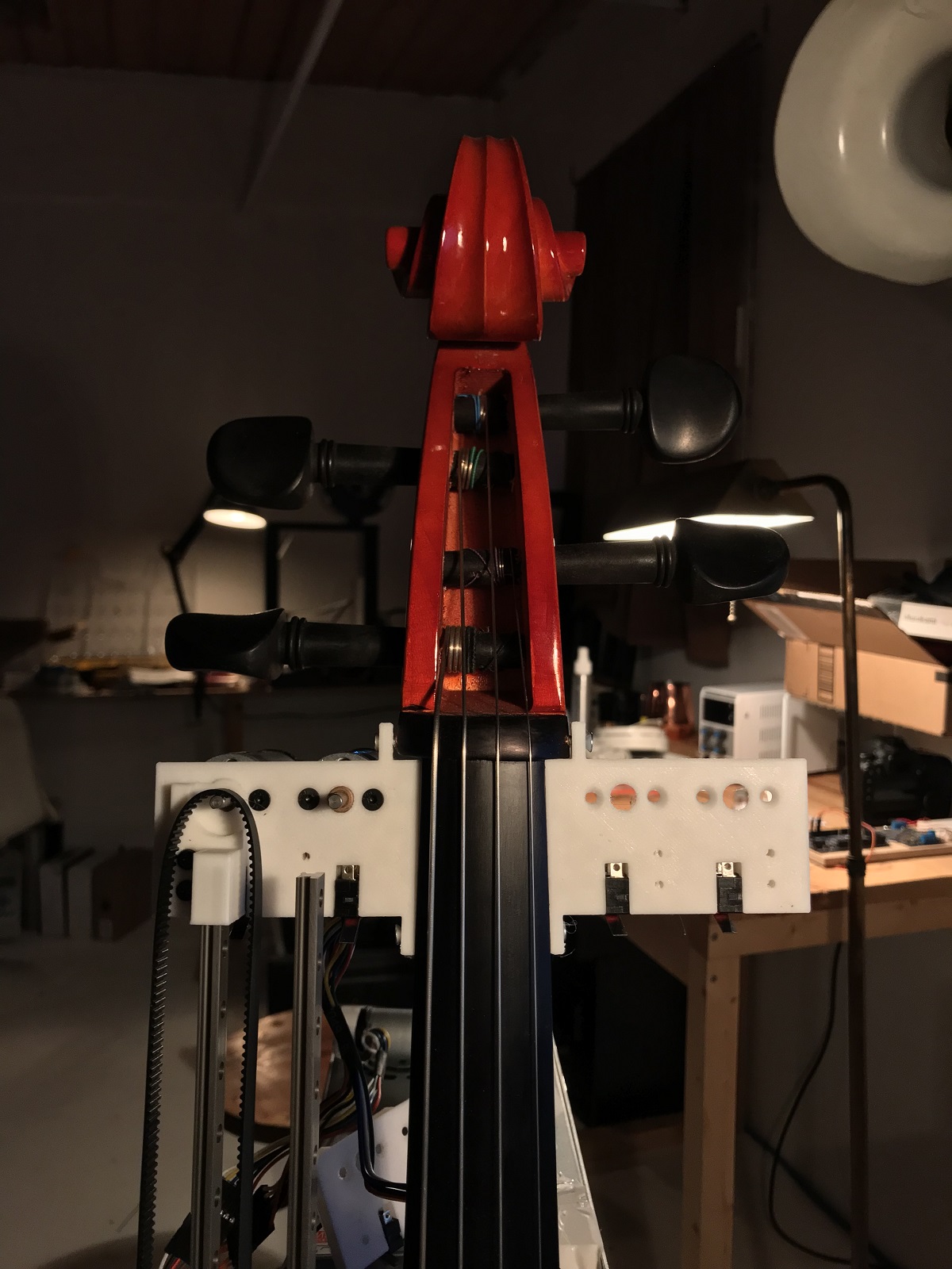
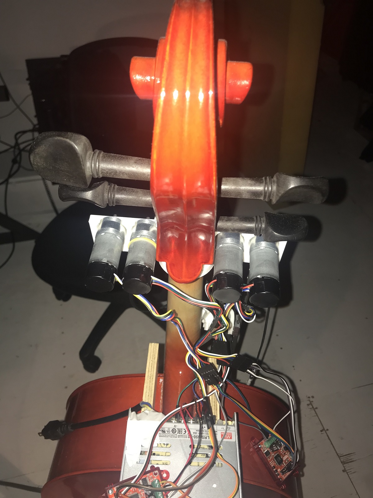
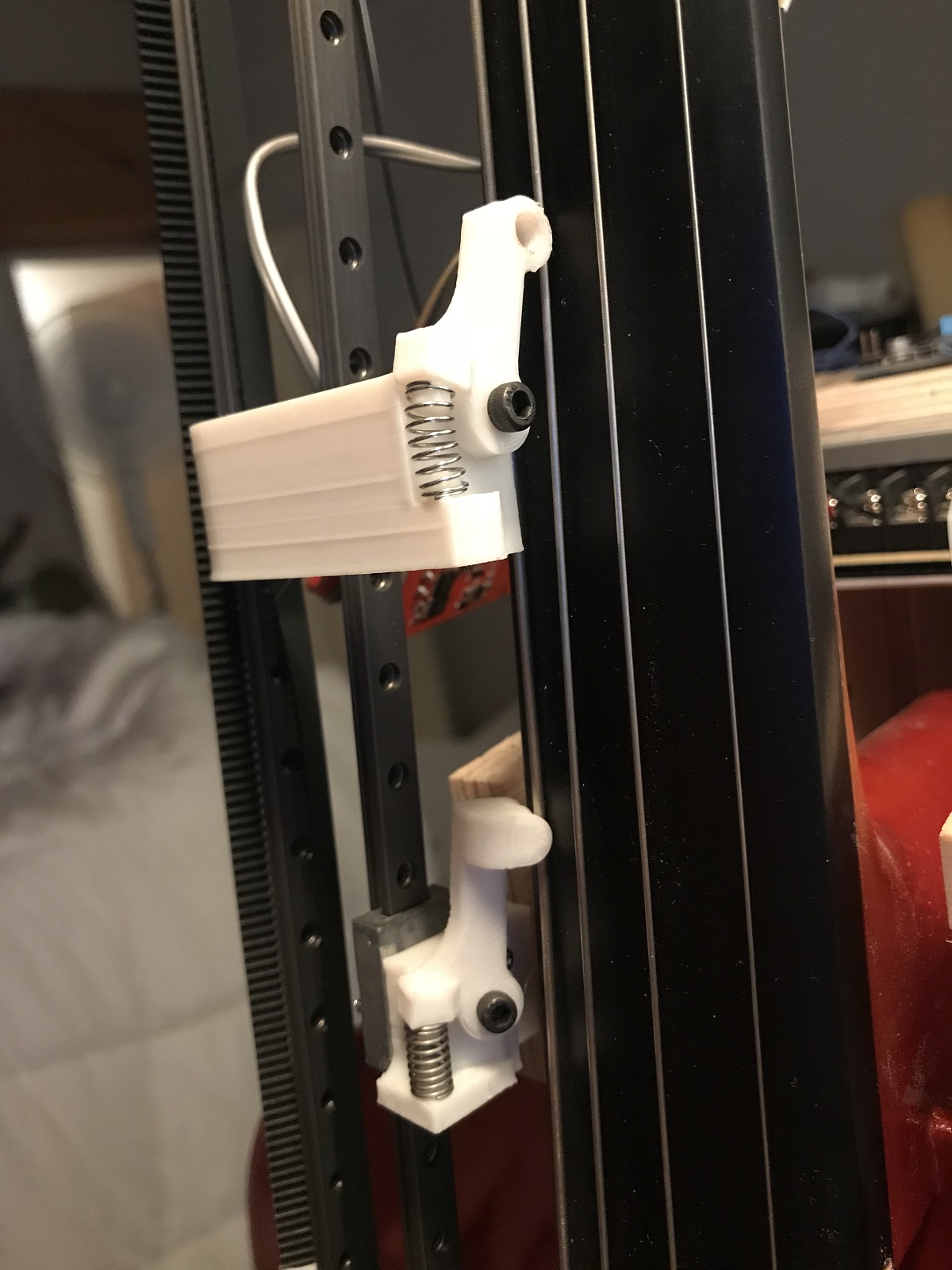
Did you design the slider systems for the fingerboards? It looks like some of the parts might be 3D printed; are the design files available anywhere?
Yes, I designed the whole robotic system from scratch. The cello is such a beautiful instrument in both design and sound. However it is designed specifically for a human body, none of the strings are parallel or in the same plane even, they all diverge towards the bridge. I didn’t want to change the actual instrument in any way for this project. This complicated the build a lot! On top of that, no two instruments are the same, so I had to make sure that the parts could be adjusted in the different planes depending on the instrument they were attached to. Another difficulty is at the top end of the finger board the strings are very close together meaning the sliders all had to be very thin so as not to collide with each other. In the end all these considerations led me to the decision that I would 3D print all the parts. With such a short build timeline, this meant I could design and print revisions of all the parts much quicker than if I was making all the parts by hand in the workshop.
The designs for the parts are not available at the moment as they are very much working prototypes! I plan to upload them for anyone that wants to see them at a stage in the future that I am happy with them.
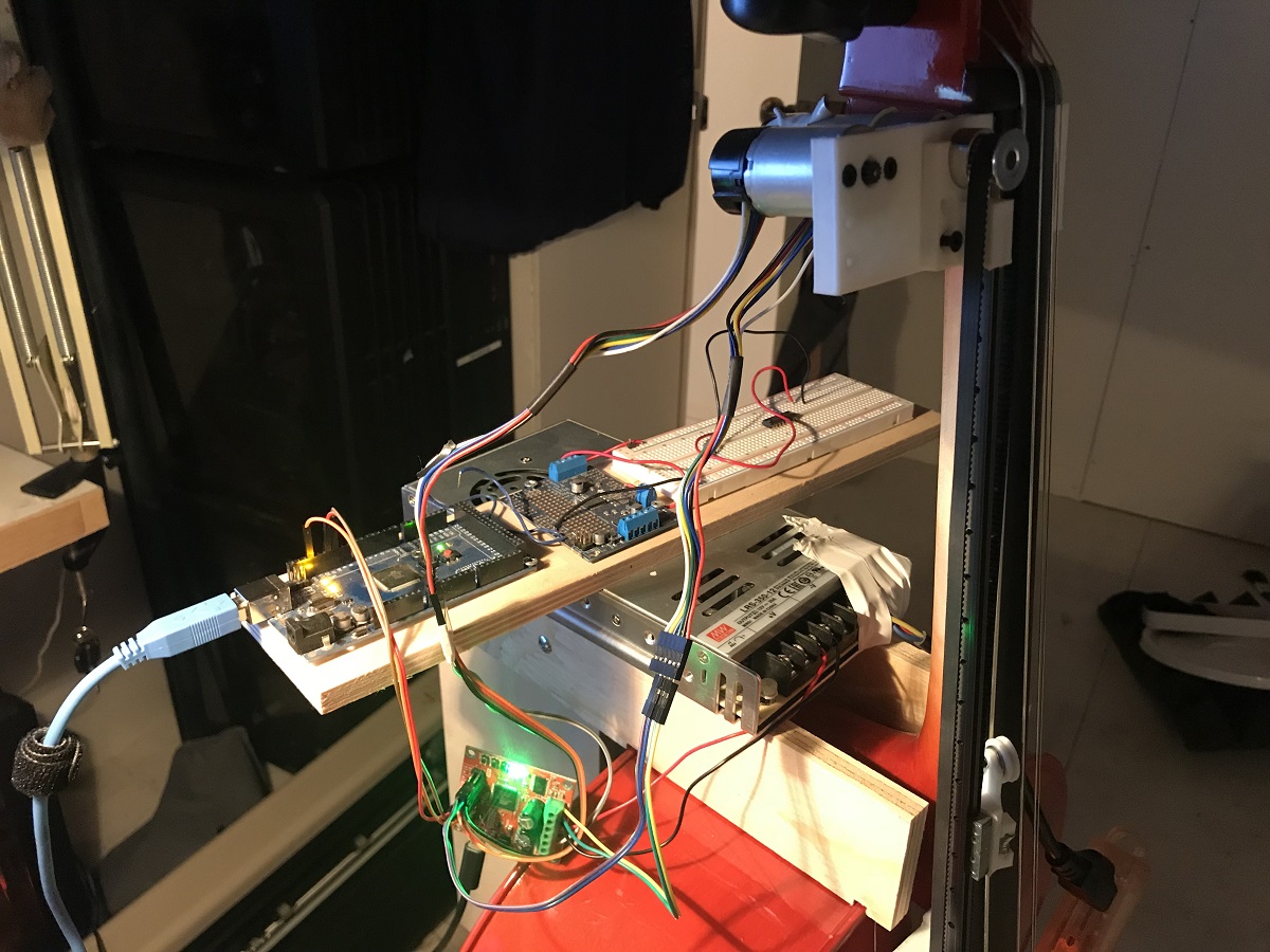 |
Can you tell us what your motor control setup is? (What motor drivers are you using, how are you processing the encoders, how are you coordinating all the movement, etc.?)
So I think I answered this in question 2. But a more general overview of the working of the cellos is – The main brain of the three cellos is the software MAX MSP (running on a PC). This would send position data over serial to an Arduino which then told the RoboClaws the next position to send the motors to. The RoboClaws were running in closed loop mode so they were dealing with the encoders directly.
We noticed you have some fans pointed at the upper bank of motors on each cello. Are the motors or controllers overheating, or is that to protect the cellos from getting too warm?
That is funny. Yes, originally I was using your 4.4:1 gear ratio 12 V motors as I really wanted the note sliders to be whizzing up and down the fingerboards like a cello maestro. But after burning out some of the motors by driving them too hard, I decided to switch to the next gear ratio down (and actually even they were getting hot). But by this point I had already locked off the design and ordered all the motors as the opening night for the piece was in three weeks. So to make sure I didn’t lose any more motors, I added some forced air cooling (just a silent fan sat on a bar stool pointed at the motors of each cello)… it added a slight bit of rock ‘n’ roll to the show.
Can you give us some details about how the music is generated?
So the project is headed towards having a fully artificially intelligent score where the music is generated on the spot and then played. The project is designed to also play in a museum environment where it will sit and play for its audience forever evolving music, with the intensity of the compositions controlled by the number of people it is playing to. However, it is currently in a more generative state where it will play music based on a set of musical rules from which it generates the music. This is where my collaborator Greg came into the project, developing patches in MAX MSP that generate the compositions and then work out which string on which cello to send each note to.
Is the piece on exhibit anywhere currently, or are there any planned exhibits coming up?
The piece was shown for a week at the SAT at the end of last year, but it was almost totally sold out so an extra week was added straight after that. The cellos are now back in my studio, where they will be upgraded. They are scheduled for another two weeks of shows at the SAT from March 24th 2020. There are some other shows in Montreal where it will be shown as part of some electronic music and tech festivals (unannounced as of right now). It is then planned for a European tour late summer 2020. It is best to keep track of the dates from my Instagram, @montreal_life_support.
Do you have a website or any social media channels where people can follow your work?
Instagram is probably the best. These are the handles:
- David Gardener: @montreal_life_support
- Greg Debicki: @woulg
Other than that I will be releasing a making-of style video documenting the build in the coming weeks on the YouTube channel.
 |
Cat tax! |
|---|
Thanks so much to David for sharing your work with us and answering all our questions. For readers in the Montreal area near the end of March/beginning of April, visit the Society for Arts and Technology’s website for showtime and ticket information.
Related products


New products: Pololu Wheels for Micro and Standard Servos

We are thrilled to announce the release of our wheels for micro and standard sized servos. These wheels are similar to our wheels for 3mm D shafts and consist of a durable ABS hub with a silicone tire. They are currently available in 40, 60, 70, and 90 mm diameter options. All but the 40 mm size feature mounting holes that are compatible with various versions of our universal mounting hubs and slots in the spokes that allow additional accessories to be mounted to the wheel such as decorations or parts of an encoder system.
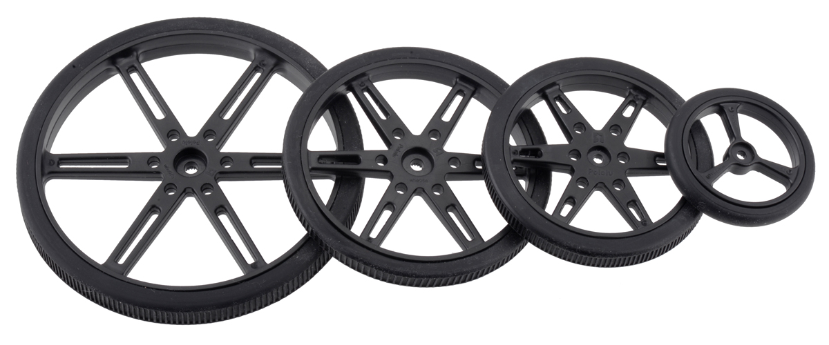 |
Black Pololu Wheels for Standard and Micro Servos – 90, 70, 60, and 40 mm diameters. |
|---|
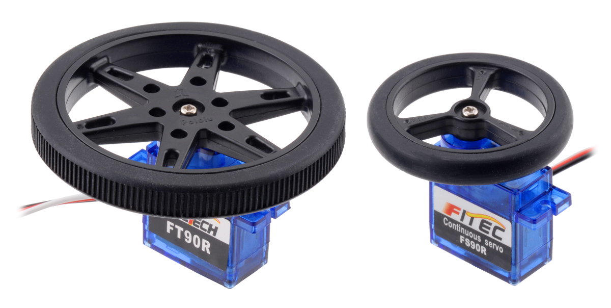 |
The 40 mm and 60 mm sizes are compatible with micro servo splines with 20 teeth and a 4.8 mm diameter and can be used with the following continuous rotation servos that we carry:
- FEETECH FS90R Micro Continuous Rotation Servo
- FEETECH FT90R Digital Micro Continuous Rotation Servo.
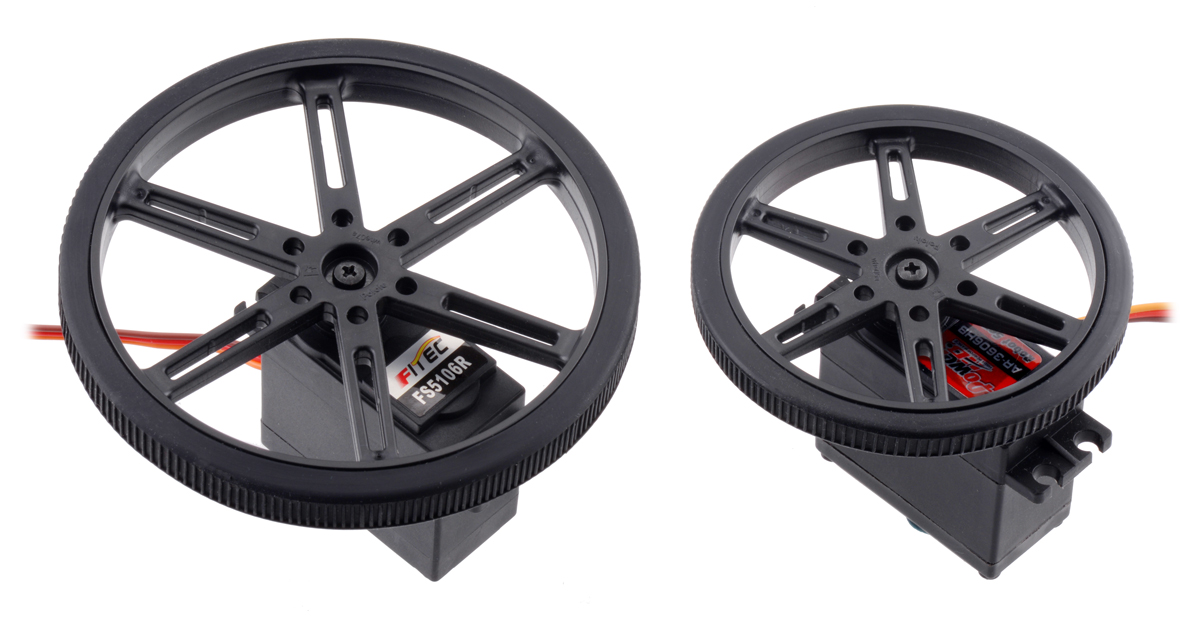 |
The 70 mm and 90 mm sizes are compatible with standard servo splines with 25 teeth and a 5.8 mm diameter and can be used with the following continuous rotation servos that we carry:
- FEETECH Continuous Rotation Servo FS5106R
- Power HD Continuous Rotation Servo AR-3606HB
- SpringRC SM-S4303R Continuous Rotation Servo
- Parallax Feedback 360° High-Speed Servo
If you plan on using the wheels with a servo not listed above, be sure to check your servo’s specifications for compatibility as servo splines are not standardized for particular sized servos.
These wheels, like many of our plastic parts, are designed by us at our Las Vegas facility and then injection molded in China. Usually, we ship bulkier parts made overseas by boat, which can take several months to get here. We were so excited about these, though, that we couldn’t wait that long! So, we had a small amount shipped by air to make them available as soon as possible. This means the initial stock of these is limited, and while we’ll have more coming by boat, the upcoming Chinese New Year will delay that even more than usual. So if you don’t want to miss out on these initial units, order yours soon!
Introductory special
As usual, we are offering an extra introductory special discount on these wheels, to help share in our celebration of releasing new products. The first hundred customers to use coupon code SERVOWHEELS can get 22% off up to 3 pairs of each size!
Related products


New products: 24V 37D Metal Gearmotors
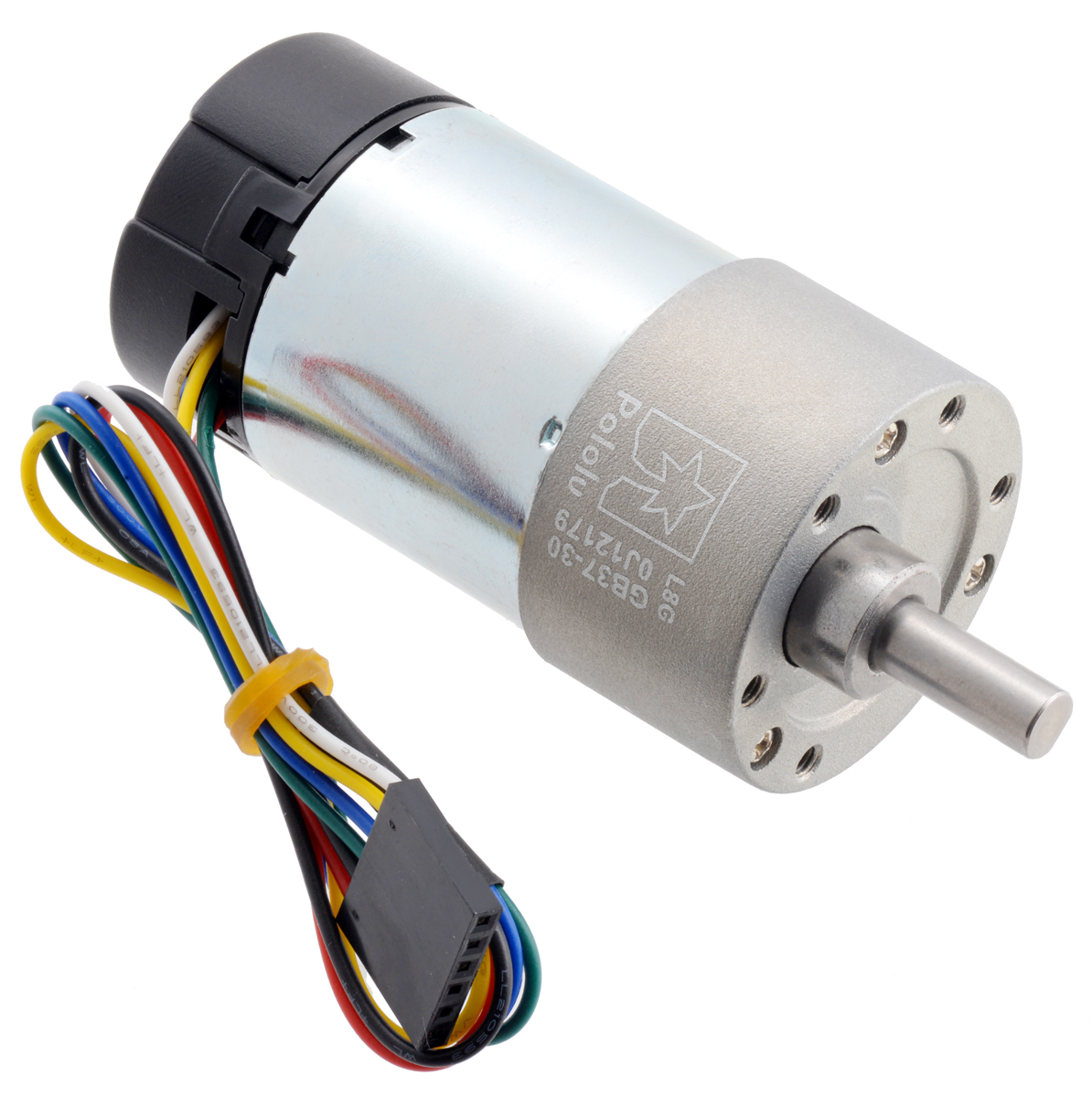 |
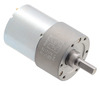
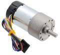
We are excited to share that we have expanded our line of 37D Metal Gearmotors to include 24 V options. These brushed DC gearmotors are the largest and most powerful we carry, measuring 37 mm (1.46″) in diameter. They are available in gear ratios ranging from 6.3:1 to 150:1 and with or without integrated 64 CPR quadrature encoders on the motor shafts. The 12 V and 24 V motors offer approximately the same performance at their respective nominal voltages, with the 24 V motor drawing half the current of the 12 V motor. The table below summarizes all of the options we now have available. Please see our newest revision of the 37D metal gearmotor datasheet (2MB pdf) for the full specifications and performance graphs for all the options.
| Rated Voltage |
Stall Current |
No-Load Current |
Gear Ratio | No-Load Speed (RPM) |
Extrapolated Stall Torque |
Max Power (W) |
 Without Encoder |
 With Encoder |
|
|---|---|---|---|---|---|---|---|---|---|
| (kg ⋅ cm) | (oz ⋅ in) | ||||||||
| 12 V | 5.5 A | 0.2 A | 1:1 (no gearbox) | 10,000 | 0.5 | 7 | – | – | item #4750 |
| 6.3:1 | 1600 | 3.0 | 42 | 12 | item #4747 | item #4757 | |||
| 10:1 | 1000 | 4.9 | 68 | 12 | item #4748 | item #4758 | |||
| 19:1 | 530 | 8.5 | 120 | 12 | item #4741 | item #4751 | |||
| 30:1 | 330 | 14 | 190 | 12 | item #4742 | item #4752 | |||
| 50:1 | 200 | 21 | 290 | 10 | item #4743 | item #4753 | |||
| 70:1 | 150 | 27 | 380 | 10* | item #4744 | item #4754 | |||
| 100:1 | 100 | 34 | 470 | 8* | item #4745 | item #4755 | |||
| 131:1 | 76 | 45 | 630 | 6* | item #4746 | item #4756 | |||
| 150:1 | 67 | 49 | 680 | 6* | item #2829 | item #2828 | |||
| 24 V | 3 A | 0.1 A | 1:1 (no gearbox) | 10,000 | 0.55 | 8 | – | – | item #4690 |
| 6.3:1 | 1600 | 3.5 | 49 | 14 | item #4688 | item #4698 | |||
| 10:1 | 1000 | 5.5 | 76 | 14 | item #4689 | item #4699 | |||
| 19:1 | 530 | 9.5 | 130 | 13 | item #4681 | item #4691 | |||
| 30:1 | 330 | 15 | 210 | 13 | item #4682 | item #4692 | |||
| 50:1 | 200 | 23 | 320 | 12 | item #4683 | item #4693 | |||
| 70:1 | 140 | 31 | 430 | 10* | item #4684 | item #4694 | |||
| 100:1 | 100 | 39 | 540 | 8* | item #4685 | item #4695 | |||
| 131:1 | 79 | 47 | 650 | 6* | item #4686 | item #4696 | |||
| 150:1 | 68 | 56 | 780 | 6* | item #4687 | item #4697 | |||
| * Output power for these units is constrained by gearbox load limits; spec provided is output power at max recommended load of 10 kg⋅cm. | |||||||||
Note: The listed stall torques and currents are theoretical extrapolations; units will typically stall well before these points as the motors heat up. Stalling or overloading gearmotors can greatly decrease their lifetimes and even result in immediate damage. The recommended upper limit for continuously applied loads is 10 kg-cm (150 oz-in), and the recommended upper limit for instantaneous torque is 25 kg-cm (350 oz-in). Stalls can also result in rapid (potentially on the order of seconds) thermal damage to the motor windings and brushes; a general recommendation for brushed DC motor operation is 25% or less of the stall current.
New products: D36V50Fx Step-Down Voltage Regulators
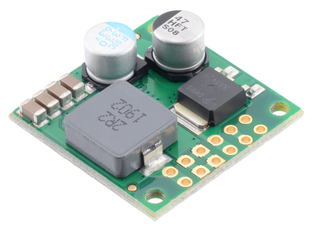 |
We have a new set of regulators to announce: the D36V50Fx family of step-down voltage regulators. Measuring a compact 1″ × 1″, these regulators support input voltages up to 50 V and can typically deliver around 5 A of current, although some versions can output much more under certain conditions.
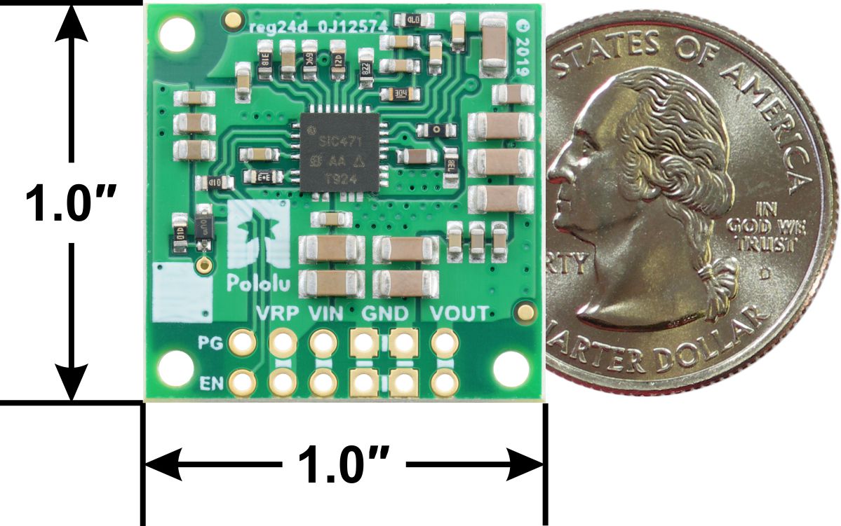 |
Step-Down Voltage Regulator D36V50Fx, bottom view with dimensions. |
|---|
The family consists of six fixed output voltage versions between 3.3 V and 12 V:
- D36V50F3: Fixed 3.3V output
- D36V50F5: Fixed 5V output
- D36V50F6: Fixed 6V output
- D36V50F7: Fixed 7.5V output
- D36V50F9: Fixed 9V output
- D36V50F12: Fixed 12V output
We can also manufacture a customized version for you here in our Las Vegas facility. For example, we could make regulators with a different output voltage that your project needs, or we could replace the 40 V reverse voltage protection MOSFET with a 20 V one for slightly improved efficiency if your input voltage will always be lower than 20 V. If you are interested in customization, please contact us for more information.
Comparison to other regulators
 |
D36V28Fx and D36V50Fx Step-Down Voltage Regulators. |
|---|
The D36V50Fx regulators are larger and more powerful counterparts to the D36V28Fx family we introduced last year, with the same input voltage ranges and mostly similar characteristics. What distinguishes the two families in performance is that the D36V50Fx regulators can provide roughly double the output current! (At the high end of the input voltage range, the difference is generally less dramatic.)
 |
Comparison of the maximum continuous current of Step-Down Voltage Regulators D36V50Fx and D36V28Fx. |
|---|
And since many of our most popular regulators are 5 V modules, here is a graph comparing the new D36V50F5 (in blue) with two of our older high-power regulators, the D24V90F5 and the D24V50F5:
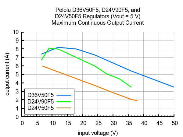 |
Comparison of the maximum continuous current of 5V Step-Down Voltage Regulators D36V50F5, D24V90F5, and D24V50F5. |
|---|
Introductory special
As usual, we are offering an extra introductory special discount on these new regulators, to help share in our celebration of releasing a new product. The first hundred customers to use coupon code D36V50FXINTRO can get up to 3 units of each version for just $11.95 each!

Related products


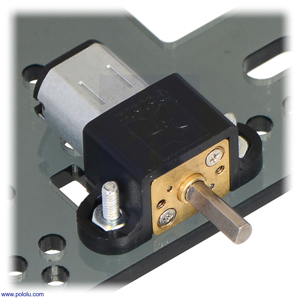
New products: micro metal gearmotors with 15:1 gear ratio
 |
We have expanded our line of micro metal gearmotors to include versions with a 15:1 gear ratio. As with all of our other micro metal gearmotors, these units are available with five different motor options:
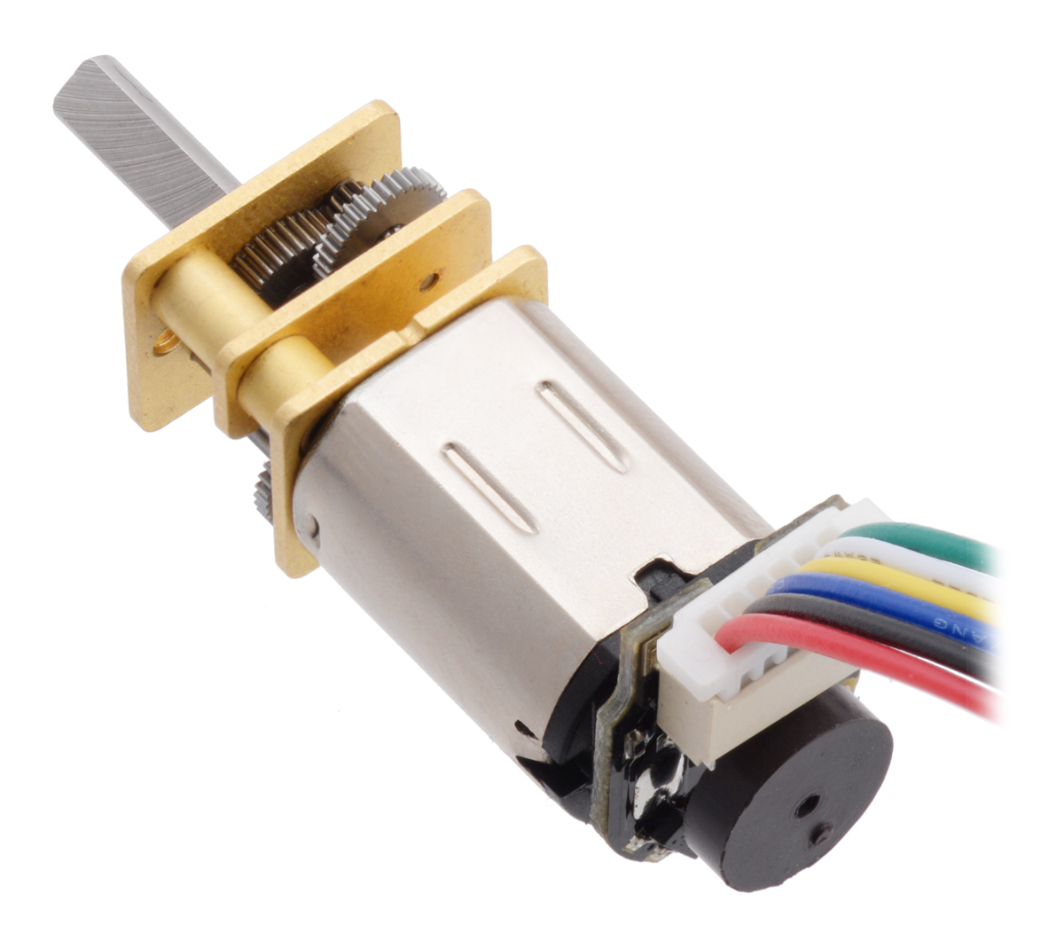 |
- Motors with precious metal brushes
- Motors with longer-life carbon brushes (HPCB)
Each motor is available with or without an extended back shaft, which rotates at the same speed as the input to the gearbox and offers a way to add an encoder, such as our encoders for micro metal gearmotors (see the picture above). This makes ten new versions in all:
| Rated Voltage |
Motor Type |
Stall Current (A) |
No-Load Current (A) |
No-Load Speed (RPM) |
Extrapolated Stall Torque |
Max Power (W) |
 Single-Shaft (Gearbox Only) |
 Dual-Shaft (Gearbox & Motor) |
|
|---|---|---|---|---|---|---|---|---|---|
| (kg ⋅ cm) | (oz ⋅ in) | ||||||||
| 12 V | high-power, carbon brushes (HPCB) |
0.75 | 0.06 | 2200 | 0.25 | 3.5 | 1.4 | 15:1 HPCB 12V | 15:1 HPCB 12V dual-shaft |
| 6 V | high-power, carbon brushes (HPCB) |
1.5 | 0.10 | 2100 | 0.25 | 3.5 | 1.3 | 15:1 HPCB 6V | 15:1 HPCB 6V dual-shaft |
| 6 V | high-power (HP) |
1.6 | 0.07 | 2000 | 0.30 | 4.2 | 1.5 | 15:1 HP 6V | 15:1 HP 6V dual-shaft |
| 6 V | medium-power (MP) |
0.67 | 0.04 | 1400 | 0.20 | 2.8 | 0.70 | 15:1 MP 6V | 15:1 MP 6V dual-shaft |
| 6 V | low-power (LP) |
0.36 | 0.02 | 860 | 0.17 | 2.4 | 0.37 | 15:1 LP 6V | 15:1 LP 6V dual-shaft |
More detailed specifications for all our micro metal gearmotors can be found in their datasheet (5MB pdf).
These new versions bring our total micro metal gearmotor selection to 130 options, with gear ratios ranging from 5:1 to 1000:1! To see them all, visit our micro metal gearmotor category, and visit our metal gearmotor category to see all of our metal gearmotor options. Keep in mind if you don’t see an option that suits your application, for sufficient volumes, modifications such as customized output shafts are available.
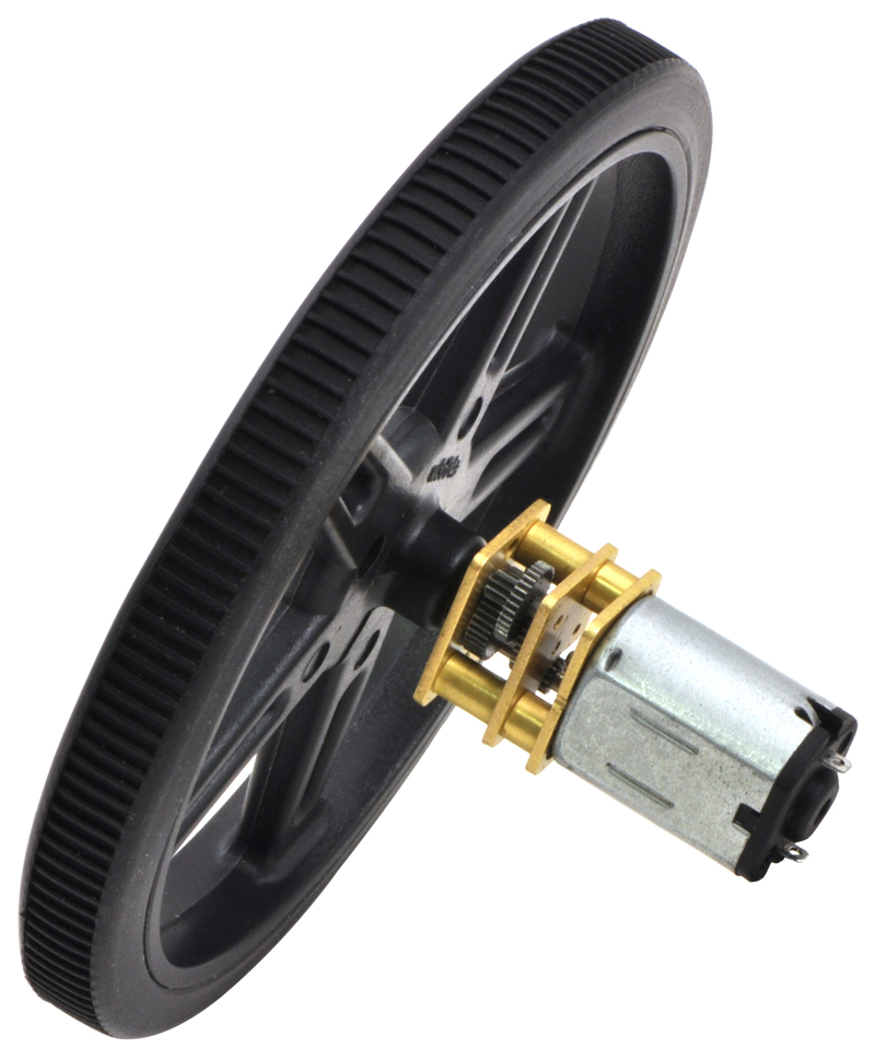
Once you find the perfect gearmotors for your project, don’t forget to check out our great selection of accessories. These were all designed either specifically for our micro metal gearmotors or with their compatibility in mind:
- Wheels and tracks
- Universal mounting hubs with #2-56, #4-40, or M3 holes.
- 12mm Hex Wheel Adapter for 3mm Shaft
- Mounting brackets in white, black, or extended options
- Magnetic and optical encoders
|
|
|

Related products


Our sale has ended, but visit our specials category for great deals all year long!
 |
Our Black Friday Sale has come to an end. As we ship out the last of our Cyber Monday orders, we’d like to point out our Specials category where you can find great deals on Pololu products any time of the year! For the last couple years, we’ve released most of our new products with special intro coupons. If you see a product’s intro banner listed in the specials category, its intro coupon is still active! There’s lots of great deals waiting to be used up, so make sure to have a look before you place your next order!
Our Black Friday/Cyber Monday sale has started!

Our Black Friday / Cyber Monday sale is going strong, and we have been working hard to make and ship the products that people are getting great deals on. Most of the sale coupons can be used on backorders if we happen to run out of stock, but you should still get your orders in early since lead times on some popular products can get long.
Please note that our usual same-day shipping guarantee is suspended during the sale, though so far we have been able to keep up with orders as they have been coming in, and we are closed Thursday, Nov 28th (tomorrow) for Thanksgiving. Happy Thanksgiving!


Home | Forum | Blog | Support | Ordering Information | Lists | Distributors | BIG Order Form | About | Contact
© 2001–2026 Pololu Corporation


