Pololu Blog
Welcome to the Pololu Blog, where we provide updates about what we and our customers are doing and thinking about. This blog used to be Pololu president Jan Malášek’s Engage Your Brain blog; you can view just those posts here.
Popular tags: community projects new products raspberry pi arduino more…
25 Years!
 |
Today is the 25th anniversary of shipping our first order! This post is a quick update about what has happened in the five years since I wrote our 20th-anniversary post. You can see more about our history in these two anniversary posts:

- Ten years in Las Vegas (Posted 5 June 2012)
- 20 years since we shipped the first Pololu product (Posted 9 April 2021)
The biggest milestone over the past five years was that we bought our building at the end of August 2021. That was such a pie-in-the-sky notion in early April 2021, when we were just a year into the pandemic and the general global outlook was very uncertain. However, that very uncertainty might have helped us, with interest rates extremely low and commercial real estate vacancies continuing to rise after the shutdowns and transitions to remote work over the previous year.
 |
Meeting with landlord on 27 April 2021. |
|---|
We had extended our lease for five years (plus some extension options) in 2018 with our long-time landlord, but he had to sell the building somewhat abruptly in 2019, giving us only six months of history with our new landlord when I went begging to him for relief right after the covid shutdowns started in March 2020. He did not help (he had dozens of tenants asking him the same thing), and he even left me with the impression that since I had a very good rental rate, I better be careful not to give him any pretext for evicting us. We hung in there for the next year, and the next time I went begging to him, in late April 2021, it was to pleeeeeease sell us the building: his ownership group has buildings all over Vegas and in several other states, while my whole life is invested in this company that is in turn very dependent on this building; with interest rates where they are now, our monthly mortgage payments would be lower than the rent we were paying!
I think he was skeptical we could get a loan, but fortunately, we were able to make a deal contingent on that loan, and then we were able to find a bank willing to lend us the money. And so the building became “ours” at the end of August 2021. “Ours” in the sense that we owed 90% of the value to the SBA and bank, but as long as we didn’t mess up, it would become more and more ours over time.
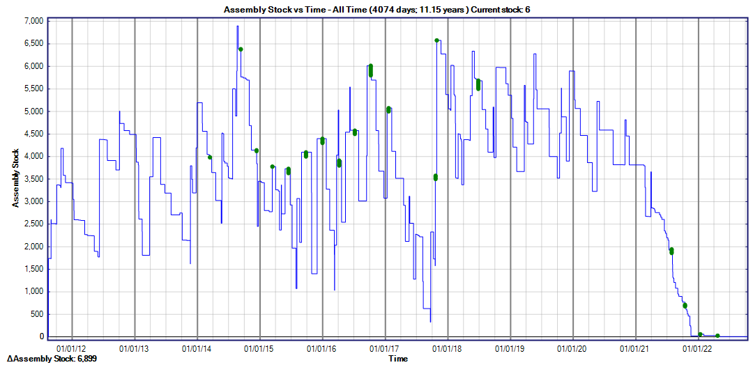 |
Inventory history for a component we ran out of during 2021-2022 chip shortage. |
|---|
The covid situation continued to improve, and now it’s mostly a distant memory, but since then we have had multiple new challenges to just keeping the business going. The biggest were the chip shortages as we came out of the pandemic, where in some cases we had to wait over two years to get parts (for example, a part I ordered in April 2021 did not get delivered until January 2024). Even with our very large inventory, that led to being completely out of key components for over a year in the worst cases. We had a big slowdown in 2024 as we were hit by the repercussions of having been out of stock on some products for an extended time and probably from some larger customers having stocked up a lot in 2022 and 2023. And as things were finally getting back to normal in 2025, we had the yugely disruptive new tariffs come into effect.
 |
Ceiling light (and/or HVAC system) replacement. |
|---|
We had done some renovations to the building in 2018-2019, but we had otherwise taken the space as-is at the end of 2011 after it had been vacant for a few years. Once the building was ours, we spent 2022 and 2023 gradually improving it, including replacing almost two dozen HVAC systems and changing over to LED lighting. The biggest project was the installation of a 305kW solar array on the roof, which I covered in a series of blog posts in late 2024:
 |
Solar panels on Pololu’s roof. |
|---|
- Part 1: Introduction and project overview starting from late 2022.
- Part 2: Installation from January 2023 through first day of operation on October 5, 2023.
- Part 3: System failures and production results during the first year of operation.
- Part 4: Analysis of electrical costs before and after our system was installed.
- Part 5: Actual system cost after tax credits and conclusion as of November 2024.
I am happy to report that we had a much better experience the second year of operation, with no major issues and over 531 MWh generated in 2025, as reported by the SolarEdge monitoring system:
 |
Pololu lifetime solar energy production as of 8 April 2026, showing 531 MWh generated in 2025. |
|---|
Here’s a monthly breakdown and comparison over the years:
 |
Pololu monthly solar energy production 5 October 2023 through 8 April 8 2026. |
|---|
It’s hard to know for sure where SolarEdge measures that generation, but once a month I can see the power company’s assessment of the situation when we get our billing statement. There are of course fluctuations as the weather changes, but the best result we got so far was for the year from August 21, 2024 through August 20, 2025, where integrating all of the charges and credits from NV Energy’s side, we used a net of 2,582 kWh. Dividing that by the 531,390 kWh generated in 2025, we generated over 99.5% of our total annual energy consumption!
 |
Jan and Paul juggling, 6 April 2001. |
|---|
I am writing so much about the building not only because a lot has happened around it in the past five years but because it has such long-term strategic relevance to Pololu’s stability and continuing to operate and grow as a manufacturer for the next 25 years. We moved or expanded almost a dozen times by the time we got to this building, but we have been at this location for almost 15 years now. Over the years and depending on where we were in our lease renewal cycle, this building has alternated between a prison and a refuge to me. It has always been bigger than what we needed, but if we were going to be committed here for many years, I wanted to make sure we had room for growth. As we got more invested in the building, with more installed equipment and procedures around how things were laid out, we also became more vulnerable to potentially losing the space. I don’t know if it’s true for sure, but I heard of long-time juggling equipment maker Dubé going out of business because of not being able to renew the lease on their location (in New York City).
Moving from a lease to a mortgage should give us much more long-term security, but it was not without its downsides. The biggest one is that we are now under more obligations to the banks than we were to the landlord, with the biggest requirement that we maintain a certain level of profitability. Especially when business gets slower, as it did for us in 2024, that becomes a big disincentive toward longer-term and riskier development projects. The pressure to maintain profitability and the difficulty in obtaining components has led to most of Pololu’s new products being simpler over the past several years. Now, with the 5-year anniversary of the building purchase coming up in less than five months, we face some uncertainty of what our interest rate will reset to (and we will also divert some energy and attention to refinancing for better terms now that we are in a better situation than we were five years ago).
The main nice thing with owning our building, even with the caveat that a bank could take it back if we fail to meet our obligations, is that every month and year we survive, the situation should be improving, as opposed to being a month closer to the unknown of a lease renegotiation. There are about 60 of us working here now, compared to the 80 at the beginning of 2020. We have lots of room to grow, but if things slow down, we can also continue operating at our reduced scale without rising real estate costs forcing us out of business.
 |
Pololu building site aerial pictures—spring 2000, left, and spring 2001, right. |
|---|
One last note on the building: in going through old county aerial photos, I saw just dirt in the spring 2000 picture and the building with cars parked around it in the spring 2001 picture, which means the building is the same age as Pololu! It was built for a public company that went bankrupt in the 2008 recession, and we have occupied the building twice as long as the original company that built it.
 |
Me and my dad, 30 May 2000. |
|---|
25 years is interesting emotionally and psychologically, as a lot can change in the five years from 20 years. After 20 years of building the company, I could still realistically think I was less than halfway done. That’s a lot less true now, as 25 more years would make me over 70 years old and close to the age my dad was when he died, which happened abruptly in May 2021. Several others at Pololu have also lost parents in the past few years.
 |
Pololu building renovation inspection, 27 April 2019. This guy is taller than me now. |
|---|
Our kids are also growing up. We five owners of Pololu have ten children among us, and with the oldest about to head off to college and nearing the age we were when we started the company, it also means we have been splitting our energy between parenting and building the company for the majority of the past 25 years. Having kids and building a company each takes a huge amount of time and effort, and each of those major life projects puts substantial limitations on the other. As our kids become less dependent on us, we should be able to put more into the company again.
I continue to be grateful to all of our customers. Thank you for your support and business over the past quarter century! Thank you also to all of the Pololu employees who work hard every day to make the world a better place. In the 20th-anniversary post, I highlighted several employees who had been with us for ten years or more; most of them are still here, which means they have now been at Pololu for 15 years or more. I am blessed to have found such great people early in my life and to be surrounded by my favorite people every day. Thank you all and here’s to the next 25 years!
New products: Motoron M3T453 Triple I²C Motor Controllers
|
|


We’re pleased to announce the release of our new Motoron M3T453 triple motor controllers. These compact boards make it easy to independently control up to three DC motors through an I²C interface; they support motor supply voltages from 4.5 V to 44 V and can supply up to 0.8 A per channel.
Four M3T453 versions are available to provide different connector options:
M3T453 with JST SH-style connectors: |
M3T453 with 0.1″-pitch through-holes: |
||
|
|


Since you can connect multiple Motoron controllers to the same I²C bus, these little modules are hard to beat for applications where you need to drive lots of small motors. In particular, the versions with JST SH-style connectors allow you to make all your motor connections modular and detachable when combined with our 2-pin JST SH-style cables and JST SH-Style Connector Board for Micro Metal Gearmotors.
Introductory special discount! Use coupon code M3T453INTRO to get any version for $14.95 each.
Related products


Black Friday sale!

Our Black Friday sale is back, with huge discounts on over 1500 of our top products! Visit the sale page to see all the available deals and add the necessary coupons to your cart. The sale runs through Monday, December 1, and the discounts can be used on backorders if we happen to run out of stock, but we encourage you to place your orders early since backorder fulfillment might take longer than usual due to the increased order volume.
Please note that during the sale, our order fulfillment times might be longer than usual, but we will do our best to get your order shipped as fast as we can. Additionally, we are closed Thursday, November 27 for Thanksgiving. Happy Thanksgiving!
New encoders with connectors for 20D mm metal gearmotors
We are excited to introduce encoders with JST PH-type connectors for our 20D mm metal gearmotors, available in two versions to better satisfy different application constraints:
- Magnetic Encoder Pair Kit with Top-Entry Connector for 20D mm Metal Gearmotors, 12 CPR, 2.7-18V
- Magnetic Encoder Pair Kit with Side-Entry Connector for 20D mm Metal Gearmotors, 12 CPR, 2.7-18V
|
|
||||
|
|


The top-entry connector allows the cable to come straight out the back, keeping things compactly in-line with the motor, while the side-entry connector is good for applications where there isn’t much space past the rear of the motor. We are also continuing to offer our original encoder board with through-holes, which allows wires to be soldered to the board for especially compact installations.
With these new encoders, you just have to solder the board to the two motor tabs, put the magnetic disc on the backshaft, and plug in your cable! And our just-released JST PH cables give you plenty of options to choose from:
|
|


| JST PH-Style 6-Pin Cables | |||||
|---|---|---|---|---|---|
| Pins | Terminations | Length | Item # | Price | |
 |
6 | double-sided (JST PH to JST PH) |
10 cm (4″) | #5643 | $3.23 |
| 16 cm (6.3″) | #5644 | $3.56 | |||
| 25 cm (10″) | #5645 | $4.04 | |||
| 40 cm (16″) | #5646 | $4.85 | |||
| 63 cm (25″) | #5647 | $6.08 | |||
| single-sided (JST PH to 0.1″ crimp pins) |
12 cm (4.5″) | #5640 | $3.34 | ||
| 30 cm (12″) | #5641 | $4.31 | |||
| 75 cm (30″) | #5642 | $6.73 | |||
The double-sided cables can be used with our new JST PH-style connector breakout boards, which are also available in top-entry and side-entry versions.
|
|


Introductory special discount! Use coupon code 20DENCINTRO to get some of these new encoders for just $6.95 per pair.
Related products


Labor Day Sale going on now!

We are having a Labor Day sale through Tuesday, September 2! Check out the sale page for more information. Please note that we will be closed Monday, so orders placed after 2 PM Pacific Time Friday, August 29 will be shipped on Tuesday, September 2.
New products: D24V7Fx 36V, 600mA low-cost step-down voltage regulators
|
|
|


We just released our D24V7Fx step-down voltage regulator family of basic buck regulators, which generate lower voltages from input voltages as high as 36 V while supporting maximum continuous output currents of 600 mA across all combinations of input and output voltages. Because they are switching regulators, they are much more efficient than linear voltage regulators, especially when the difference between the input and output voltage is large. This family includes six versions with fixed output voltages ranging from 3.3 V to 12 V:
| Regulator | Output voltage | Max continuous output current |
Input voltage range1 | Size | Special features | Price |
|---|---|---|---|---|---|---|
| #5592: D24V7F3 | 3.3 V | 600 mA | 4 V – 36 V | 0.34″ × 0.54″ | Short-circuit protection, thermal shutdown |
$2.75 |
| #5593: D24V7F5 | 5 V | 5.1 V – 36 V | ||||
| #5594: D24V7F6 | 6 V | 6.1 V – 36 V | ||||
| #5595: D24V7F7 | 7.5 V | 7.6 V – 36 V | ||||
| #5596: D24V7F9 | 9 V | 9.2 V – 36 V | ||||
| #5597: D24V7F12 | 12 V | 12.2 V – 36 V | ||||
| Note 1: Minimum input voltage is subject to dropout voltage considerations; see the dropout voltage section of product pages for more information. | ||||||
We manufacture these boards in-house at our Las Vegas facility, so if one of the stock voltages doesn’t fit your needs, we can customize these regulators to output other voltages. If you are interested in customization, please contact us for a quote.
 |
The main distinguishing feature of this regulator is its small size and low cost. At just $2.75 in single-unit quantities, it is our lowest-price regulator yet! We were able to achieve this by having one of our high school summer interns do the board design:
 |
High-school summer intern routing the D24V7Fx regulator PCB, July 2025. |
|---|
I’m kidding about that making the price lower, of course. Our engineers still went over everything, and unlike some competing products you might encounter, we provide detailed performance data such as the quiescent current characteristics:
 |
Also, each production unit is fully automatically optically inspected and tested. We have been putting a lot of effort into automating our testing and packaging, and that is the real key to being able to offer these low prices. More behind-the-scenes information on the robots making our products coming soon!
Introductory special discount! Use coupon code D24V7FXINTRO to try out these new regulators for just $2.22 each.
Related products


New product: A89301-Based Sensorless Brushless Motor Controller, 50V, 11A
 |
 |
Yes, you read that right: brushless! We’re excited to finally announce our A89301-Based Sensorless Brushless Motor Controller, 50V, 11A, our first board designed to control a brushless DC motor.
Pololu has never offered any BLDC motor drivers or controllers until now (we’ve had stepper motor drivers for a long time, but that’s typically not what people mean when they ask for a brushless motor driver), and I think it’s easier to appreciate some of our reasons for this if you look into their principles of operation.
A brushed DC motor can easily be driven with a simple direct current produced from a constant voltage, and its speed can be controlled by varying that voltage proportionally (or by using PWM, which effectively produces a lower average voltage). This is because it has a commutator and some contacts, or “brushes”, that switch the direction of the current in the windings as they rotate inside a fixed magnetic field, and that maintains a steady torque on the motor shaft to keep it spinning. Consequently, the simplest brushed DC motor drivers are not much more than amplifiers that turn low-voltage, low-current control signals into higher power outputs capable of driving a motor.
By contrast, the construction of a brushless DC motor is relatively simple. The coils are located on the fixed part of the motor (stator) and are directly connected to the motor’s terminals, and the magnets are on the rotating part (rotor) instead. Eliminating the brushes and commutator accounts for some of the advantages of brushless motors, including higher efficiency (partly due to less friction) and longer lifetimes (fewer parts to wear out) compared to brushed motors. The trade-off for this reduced mechanical complexity is increased control complexity: something else now has to switch the coil currents appropriately to maintain a steady torque on the rotor, and that is the responsibility of the brushless motor driver.
 |
A pair of disassembled DC motors. Brushed motor (left): end cap with brushes, rotor with coils and commutator, case with fixed magnets. Brushless outrunner motor (right): rotor with magnets and case, stator with coils. |
|---|
In order to produce torque, a motor’s windings must generate magnetic forces tangential to the axis of rotation. (I saw an analogy that compares this to using a wrench: you can torque a bolt by applying a tangential force to the wrench handle, but pushing or pulling on the wrench parallel to the handle doesn’t do anything useful.) Since a brushless motor’s magnets rotate, the fixed coils’ magnetic fields must also rotate to keep acting on the rotor tangentially, and this means the coils need to be energized in a rotating sequence.
The simplest way to do this is with an open-loop technique that simply drives the brushless motor using a sequence with fixed timing. However, for better reliability and efficiency, it is helpful to know the actual position of the rotor so that the timing of the sequence can be adjusted accordingly. There are two approaches to doing this, each with their own upsides and downsides: sensored control relies on a position sensor in the motor (like an encoder) to directly measure its position, while sensorless control uses the back-EMF (electromotive force) induced on the coils by the motor’s rotation to calculate its position.
I hope this brief overview conveys some of the additional considerations that are involved in making a brushless DC motor control system. This complexity, and the wide range of electronic parts released by various manufacturers to address it, means that it’s been hard for us to decide on a direction to take when it came to trying to design our own brushless driver or controller. Another factor was that we don’t sell any brushless motors (yet), which made it kind of a chicken-and-egg problem: does it make sense for us to develop a brushless driver when we have no brushless motors, and does it make sense for us to source brushless motors to sell when we have nothing to drive them?
 |
Of course, to resolve that dilemma, you have to start with one or the other, and Allegro offering development support for their A89301 brushless DC gate driver IC made it an easy decision for us to move forward with a board for it. Our A89301-Based Sensorless Brushless Motor Controller, 50V, 11A combines the A89301 with external MOSFETs to enable sensorless control of 3-phase BLDC motors at voltages from 5.5 V to 48 V and with phase currents up to 11 A. The A89301 uses a fully-integrated field-oriented control (FOC) algorithm that computes the exact position of the rotor so that the coil currents can be controlled accordingly, optimizing torque and efficiency. It accepts speed inputs via analog voltage, PWM duty cycle, pulse frequency, or I²C signals to simplify the process of getting a brushless motor running without having to write your own complex low-level motor control code. We offer versions with soldered header pins and terminal blocks or without through-hole connectors.
Introductory special discount! Use coupon code A89301INTRO to get either version for $19.95 each.
To make use of all of the A89301 IC’s features and settings, including lock (stall) detection and multiple motor startup options, it needs to be configured through I²C. Our board’s 4-pin I²C connector (Qwiic and STEMMA QT compatible) makes it easy to connect it to one of our USB-to-I²C Adapters and use the Pololu A89301 Configuration Utility software for Windows (based on Allegro’s own evaluation board software) to interface with the A89301.
 |
The Pololu A89301 Configuration Utility software. |
|---|
 |
An A89301-Based Sensorless Brushless Motor Controller connected to a computer with a Pololu Isolated USB-to-I²C Adapter (IOREF shorted to 2V8). |
|---|
This is our first brushless motor control solution, and we definitely don’t intend it to be our last. While we have plans for other products, we’re also interested in hearing from you: What are you looking for in a BLDC motor system? What kinds of brushless motors, drivers, and controllers would you like to see us offer?
Related products


New products: JST SH-style connector boards
|
|
|


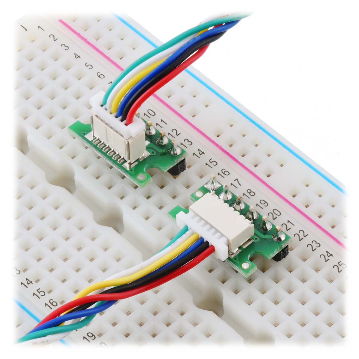
We have released a series of breakout boards for our new JST SH-type cables that serve as adapters between these cables and breadboard-compatible 0.1″ through-holes. The new boards are available in pin counts from 2 through 5 and in top-entry and side-entry variations. We also have existing 6-pin versions that we originally released as accessories for our micro metal gearmotor encoders, so the through-holes are labeled on the silkscreen according to the pins they would map to on our encoders, but these can also be used as general-purpose breakout boards for our 6-pin cables. Here’s the full selection:
| Top entry | Side entry |
|---|---|
| 2-pin | |
 |
 |
| 3-pin | |
 |
 |
| 4-pin | |
 |
 |
| 5-pin | |
 |
 |
| 6-pin | |
 |
 |
Independence Day sale going on now!

We are having an Independence Day sale starting now through Monday, July 7! Check out the sale page for more information. Please note that we will be closed Friday, July 4 in observance Independence Day, so orders placed after 2 PM Pacific Time Thursday, July 3 will be shipped on Monday, July 7.
New products: 40 new JST SH-style cables
You may have noticed several of our newer boards have JST SH-style connectors on them, from 2 pins on these micro metal gearmotor connector boards to 3 pins on these digital distance sensors to 4 pins on these contactless current sensor carriers and several I2C products including our USB-to-I2C adapters. We now have a series of compatible JST SH-style female cables to go with them. We are stocking them in a variety of lengths, pin counts, and termination styles, making 40 new cables in all to choose from!
| Pins | Terminations | Length | Item # | |
|---|---|---|---|---|
 |
1×2 | double-sided (female-female) |
10 cm (4″) | #5503 |
| 16 cm (6.3″) | #5504 | |||
| 25 cm (10″) | #5505 | |||
| 40 cm (16″) | #5506 | |||
| 63 cm (25″) | #5507 | |||
| single-sided (female- unterminated) |
12 cm (4.5″) | #5500 | ||
| 30 cm (12″) | #5501 | |||
| 75 cm (30″) | #5502 |
| Pins | Terminations | Length | Item # | |
|---|---|---|---|---|
 |
1×3 | double-sided (female-female) |
10 cm (4″) | #5513 |
| 16 cm (6.3″) | #5514 | |||
| 25 cm (10″) | #5515 | |||
| 40 cm (16″) | #5516 | |||
| 63 cm (25″) | #5517 | |||
| single-sided (female- unterminated) |
12 cm (4.5″) | #5510 | ||
| 30 cm (12″) | #5511 | |||
| 75 cm (30″) | #5512 |
| Pins | Terminations | Length | Item # | |
|---|---|---|---|---|
 |
1×4 | double-sided (female-female) |
10 cm (4″) | #5523 |
| 16 cm (6.3″) | #5524 | |||
| 25 cm (10″) | #5525 | |||
| 40 cm (16″) | #5526 | |||
| 63 cm (25″) | #5527 | |||
| single-sided (female- unterminated) |
12 cm (4.5″) | #5520 | ||
| 30 cm (12″) | #5521 | |||
| 75 cm (30″) | #5522 |
| Pins | Terminations | Length | Item # | |
|---|---|---|---|---|
 |
1×5 | double-sided (female-female) |
10 cm (4″) | #5533 |
| 16 cm (6.3″) | #5534 | |||
| 25 cm (10″) | #5535 | |||
| 40 cm (16″) | #5536 | |||
| 63 cm (25″) | #5537 | |||
| single-sided (female- unterminated) |
12 cm (4.5″) | #5530 | ||
| 30 cm (12″) | #5531 | |||
| 75 cm (30″) | #5532 |
| Pins | Terminations | Length | Item # | |
|---|---|---|---|---|
 |
1×6 | double-sided (female-female) |
10 cm (4″) | #5543 |
| 16 cm (6.3″) | #5544 | |||
| 25 cm (10″) | #5545 | |||
| 40 cm (16″) | #5546 | |||
| 63 cm (25″) | #5547 | |||
| single-sided (female- unterminated) |
12 cm (4.5″) | #5540 | ||
| 30 cm (12″) | #5541 | |||
| 75 cm (30″) | #5542 |
The JST SH-style connector has a 1 mm pitch, making it a good choice for small modules, and the wires are 28 AWG. The double-sided cables have twisted wires and female connectors on both ends, while the single-sided versions have a connector on one end and unterminated wires on the other. The single-ended versions can easily be cut to shorter if desired, and remember that you can also cut the double-sided cables in half to get single-sided cables that are 5 cm, 8 cm, and 20 cm long.
The 4-pin versions are compatible with SparkFun’s Qwiic and Adafruit’s STEMMA QT.
We’ve had 6-pin cables for our Micro Metal Gearmotor encoders for years, but with this new line of cables, we’re offering a 6-pin version that matches the standardized color order, with black always corresponding to pin 1 and red always corresponding to pin 2. For reference, here is our selection of those original 6-pin cables, which have the green wire on pin 1:
| Pins | Terminations | Length | Item # | |
|---|---|---|---|---|
 |
1×6 | double-sided (female-female) |
10 cm (4″) | #4765 |
| 16 cm (6.3″) | #4766 | |||
| 25 cm (10″) | #4767 | |||
| 40 cm (16″) | #4768 | |||
| 63 cm (25″) | #4769 | |||
| single-sided (female- unterminated) |
12 cm (4.5″) | #4762 | ||
| 30 cm (12″) | #4763 | |||
| 75 cm (30″) | #4764 |
What new products would you like to see with connectors for these cables?


Home | Forum | Blog | Support | Ordering Information | Lists | Distributors | BIG Order Form | About | Contact
© 2001–2026 Pololu Corporation


