Pololu Blog »
Posts tagged “arduino”
You are currently viewing a selection of posts from the Pololu Blog. You can also view all the posts.
Popular tags: community projects new products raspberry pi arduino more…
New products: Motoron dual high-power motor controllers
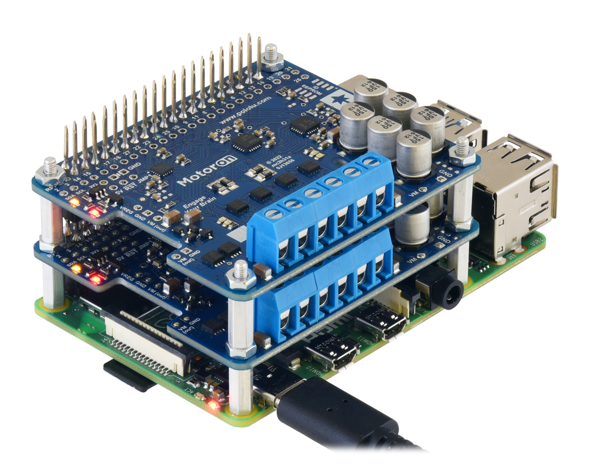 |
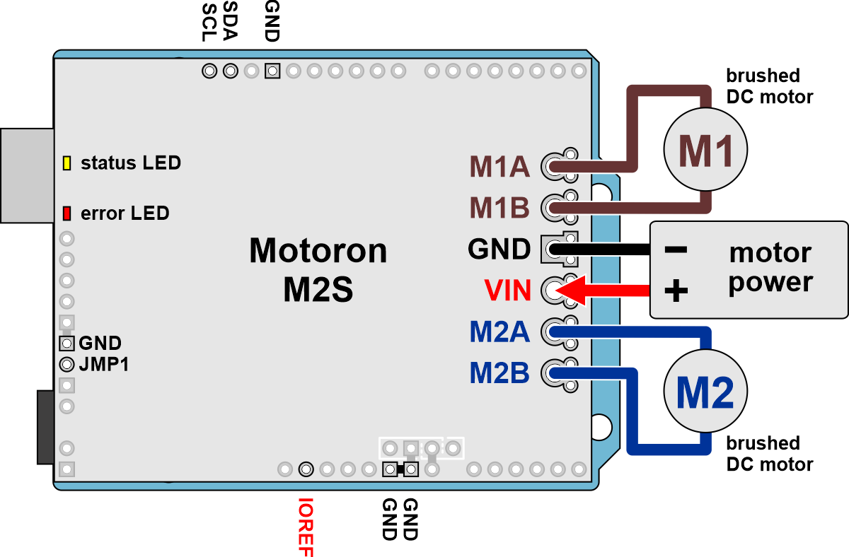
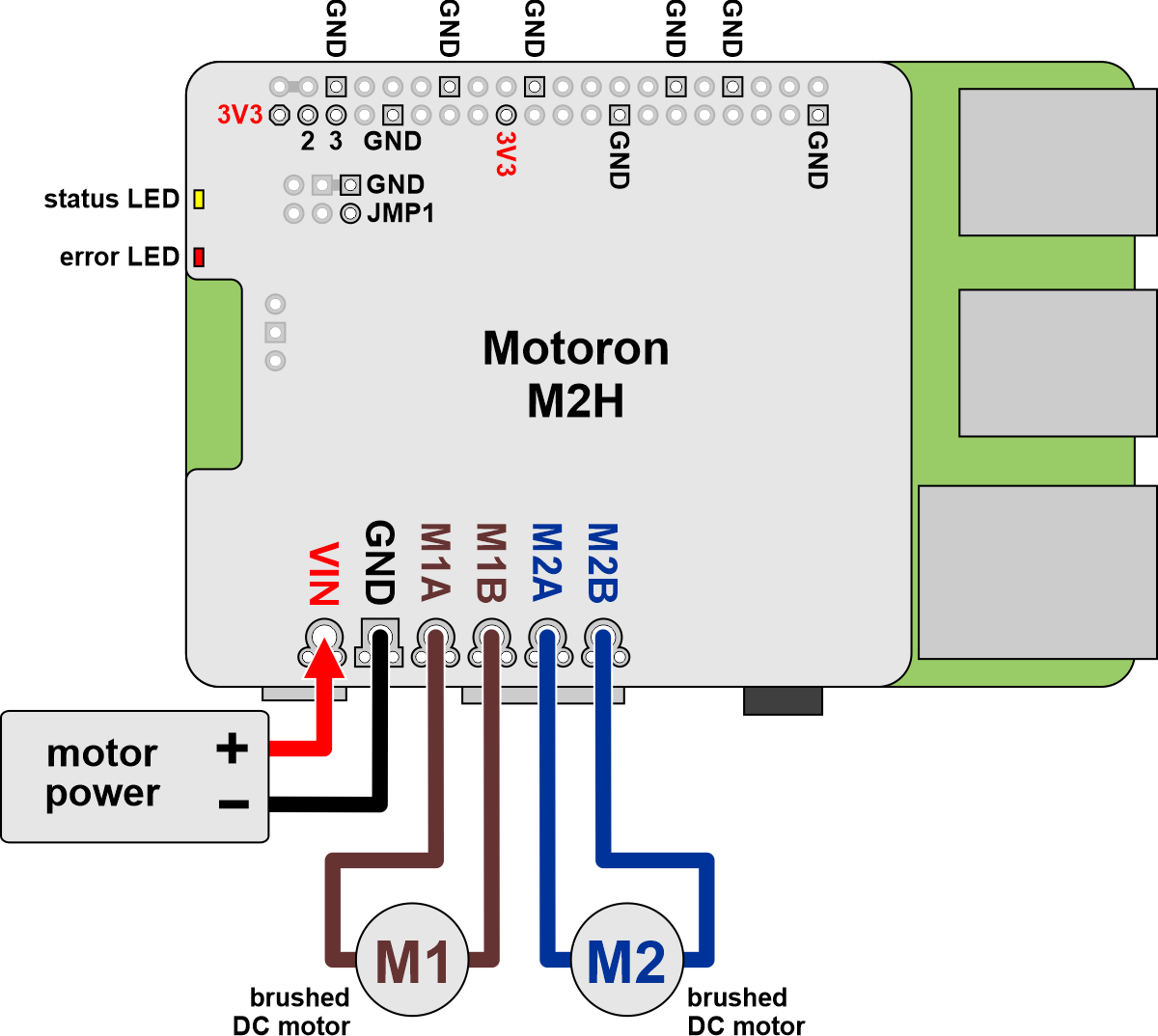
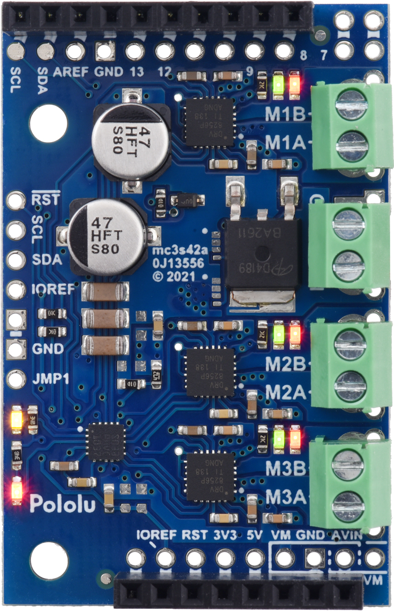
We’ve expanded our Motoron series of motor controllers with some dual high-power motor controllers: the Motoron M2S family for Arduino and Motoron M2H family for Raspberry Pi! These new Motorons have the same I²C interface as the M3S256 and M3H256, and though they only have two channels instead of the three on their smaller counterparts, they can drive much more powerful motors with up to 20 A of current at 30 V or 16 A at 40 V. There are four combinations of voltage and current ranges, available in versions designed to work as Arduino shields and as Raspberry Pi expansions.
|
|
These eight additions bring the Motoron family up to a total of ten members overall:
| Motoron Motor Controllers | |||||
|---|---|---|---|---|---|
 M3S256  M3H256 |
 M2S24v14  M2H24v14 |
 M2S24v16  M2H24v16 |
 M2S18v18  M2H18v18 |
 M2S18v20  M2H18v20 |
|
| Motor channels: | triple (3) | dual (2) | |||
| Max input voltage: |
48 V | 40 V1 | 30 V1 | ||
| Max nominal battery voltage: |
36 V | 28 V | 18 V | ||
| Max continuous current per channel: |
2 A | 14 A | 16 A | 18 A | 20 A |
| Available versions for Arduino: |
M3S256 | M2S24v14 | M2S24v16 | M2S18v18 | M2S18v20 |
| Available versions for Raspberry Pi: |
M3H256 | M2H24v14 | M2H24v16 | M2H18v18 | M2H18v20 |
| 1 Absolute maximum. | |||||
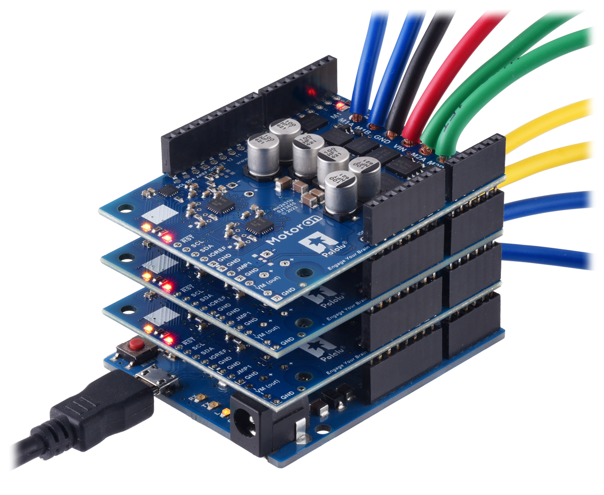
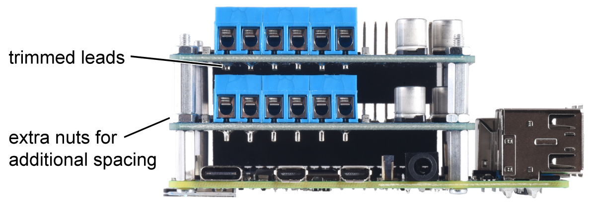
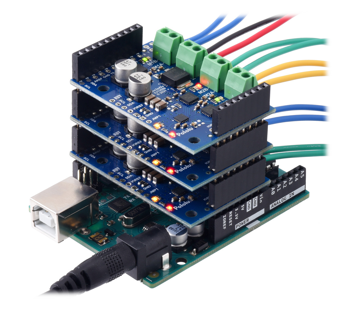
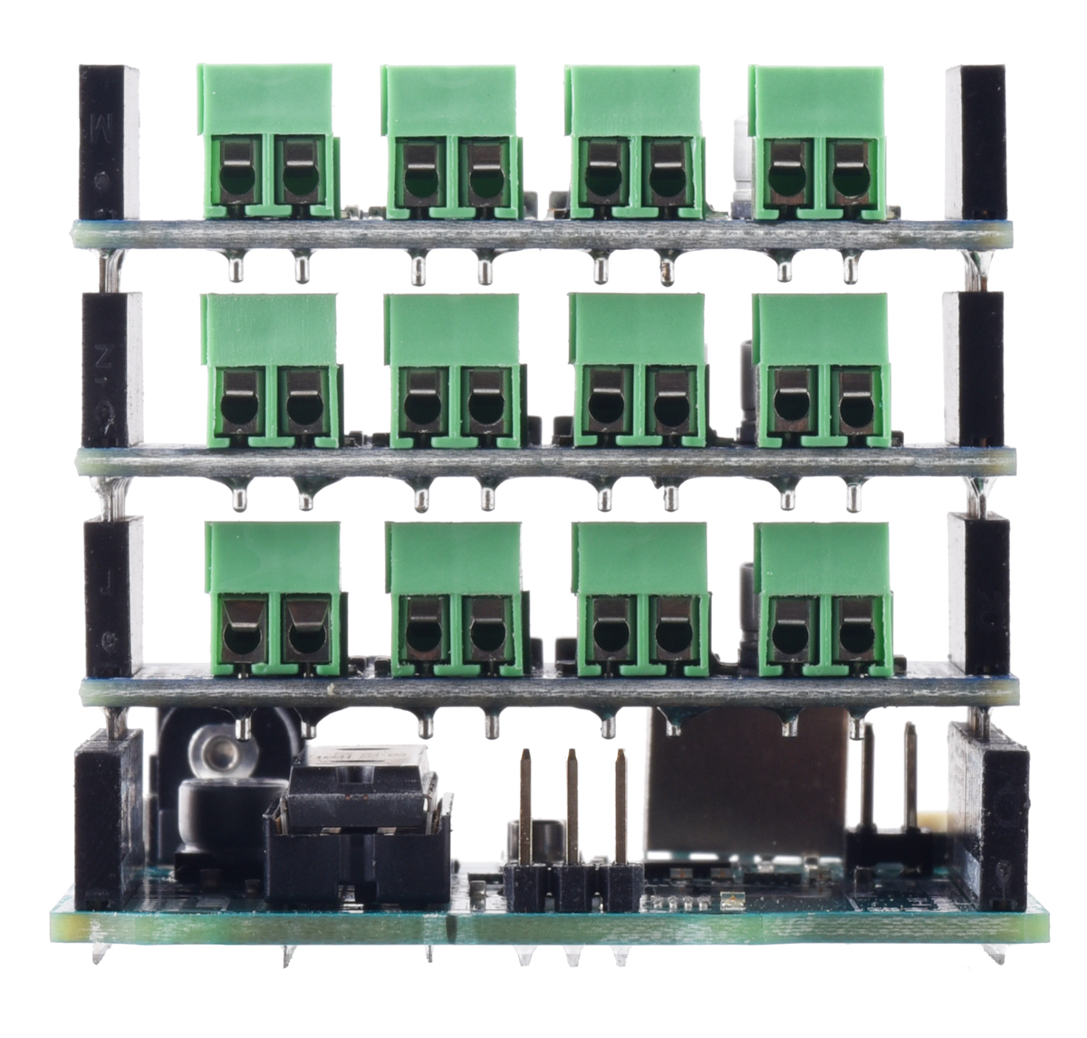
As with the smaller Motorons, the high-power versions can also be stacked and their addresses configured to allow many motors to be controlled with only one I²C bus. For a stack of M2S boards on an Arduino, we recommend soldering thick wires to the kit or board-only version because 5mm terminal blocks are tall enough that they would cause short circuits within the stack. However, the M2H boards can be set up to stack safely by trimming the terminal block leads and adding extra nuts to the standoffs for additional spacing.
|
|
It’s also possible to stack different kinds of Motoron controllers so you can control different kinds of motors:
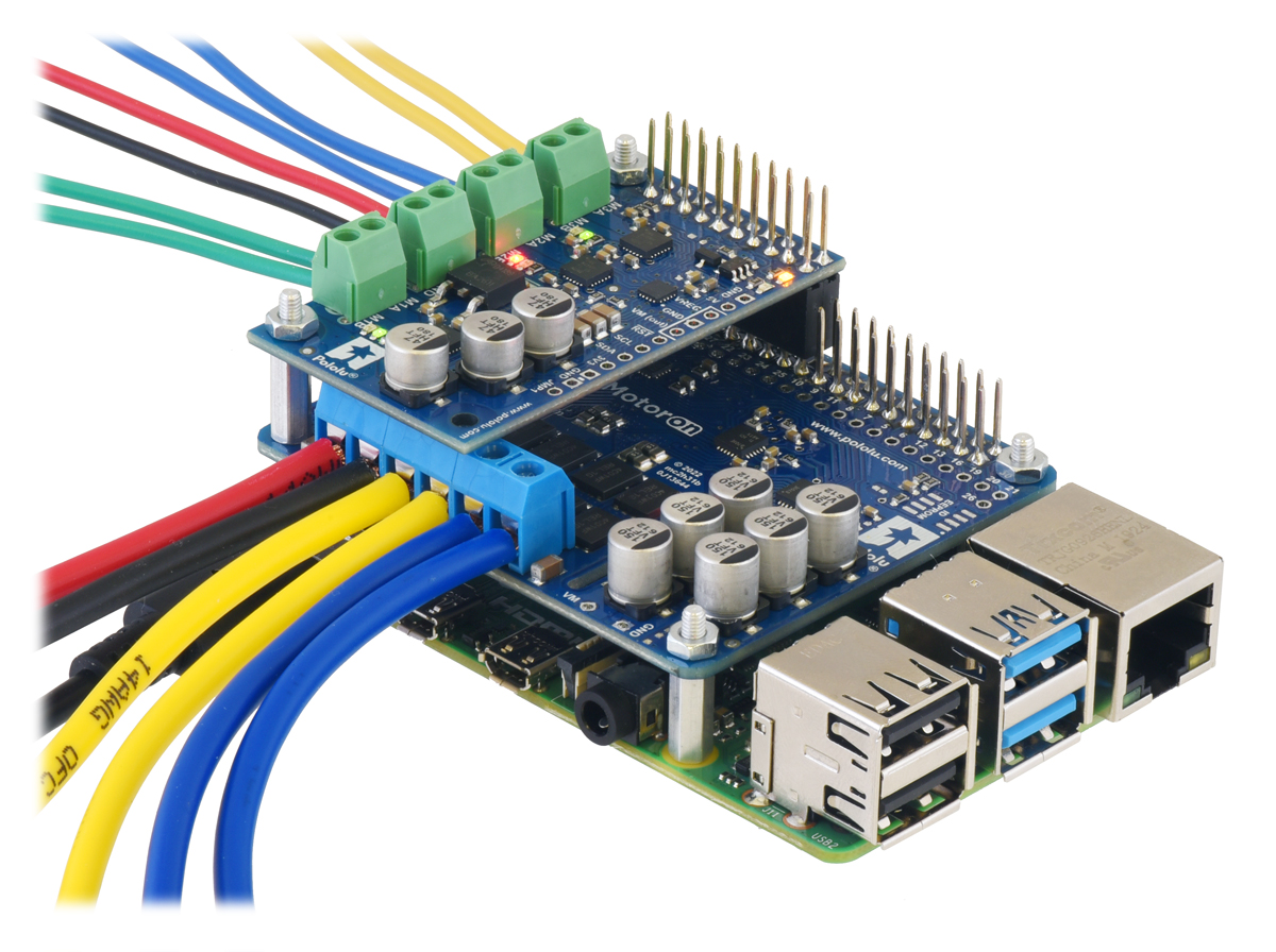 |
A Motoron M2H and a Motoron M3H256 being controlled by a Raspberry Pi, allowing for independent control of five motors. |
|---|
Unfortunately, the current state of the electronics supply chain is affecting how we’re making and selling these Motorons. In the past, when we released boards in multiple versions that have different MOSFET footprints, it was primarily to get us different power levels. Typically, we would make a less expensive one with smaller, lower-power MOSFETs and a more expensive one with bigger, higher-power MOSFETs. While we’re still doing this kind of thing with the M2S and M2H Motorons (the 24v14 and 18v18 use smaller MOSFETs and the 24v16 and 18v20 use bigger ones), in this case, it’s largely about maximizing parts options.
When we don’t know how many months (or years!) it will take for us to get more of a MOSFET, it’s hard to offer a product line where each model is totally dependent on one specific part. So we’ve chosen to make the different Motoron versions less distinct; the specified performance and prices are not as different between the small- and big-MOSFET versions since we want them to be viewed more interchangeably. Their performance specifications are also a little on the conservative side to give us more room to use different MOSFETs.
Even with those considerations, we still haven’t been able to get the parts to make as many of these new high-power Motorons as we want to. That’s why they are listed with a “Rationed” status in our store, with lower stock and higher pricing than we’d like. But we hope that as parts availability improves, we will eventually be able to ease up on those restrictions.
In fact, that just happened with the smaller M3S256 and M3H256: we received some long-awaited critical components that will let us make a lot more of those, so you should see more in stock soon, and we’ve already removed their Rationed status and lowered their prices!
Related products


New product: Motoron M3S256 Triple Motor Controller Shield
 |
 |
We’re excited to announce the launch of our new Motoron M3S256 Triple Motor Controller Shield! This I²C motor controller is designed to plug into an Arduino or Arduino-compatible board and control up to three bidirectional brushed DC motors at voltages from 4.5 V to 48 V with continuous currents of up to 2 A per channel. However, what really sets the Motoron apart from our other motor shields is that you can easily stack multiple boards to control even more motors at once!
Unlike basic motor driver shields that are best for driving just a few channels using the Arduino’s hardware PWM outputs, the Motoron M3S256 has its own on-board microcontroller with an I²C interface, letting you communicate with a stack of many controllers using only two I/O lines. Each Motoron can be configured to have a unique I²C target address, ensuring that every shield can be addressed individually and every motor can be controlled independently. For synchronized motion, you can even signal all the motors on several controllers to change speed at the same time with a single I²C command.
We provide an Arduino library for the Motoron that makes it easy to send it commands and configure its many settings, including motion parameters and error handling options. Working with multiple Motoron controllers is as simple as calling a few functions once you have set up their I²C addresses:
// Set up acceleration and deceleration limits for Motoron #1
mc1.setMaxAcceleration(1, 80);
mc1.setMaxDeceleration(1, 300);
mc1.setMaxAcceleration(3, 50);

// Set up acceleration and deceleration limits for Motoron #2
mc2.setMaxAcceleration(2, 50);
mc2.setMaxDeceleration(2, 200);

// Drive the motors

mc1.setSpeed(1, -800);
mc1.setSpeed(2, 100);
mc1.setSpeed(3, -100);

mc2.setSpeed(1, -400);
mc2.setSpeed(2, 50);
mc2.setSpeed(3, 300);
Alternatively, if you are not using a microcontroller board with the standard Arduino form factor, it is almost as easy to use the Motoron on a breadboard.
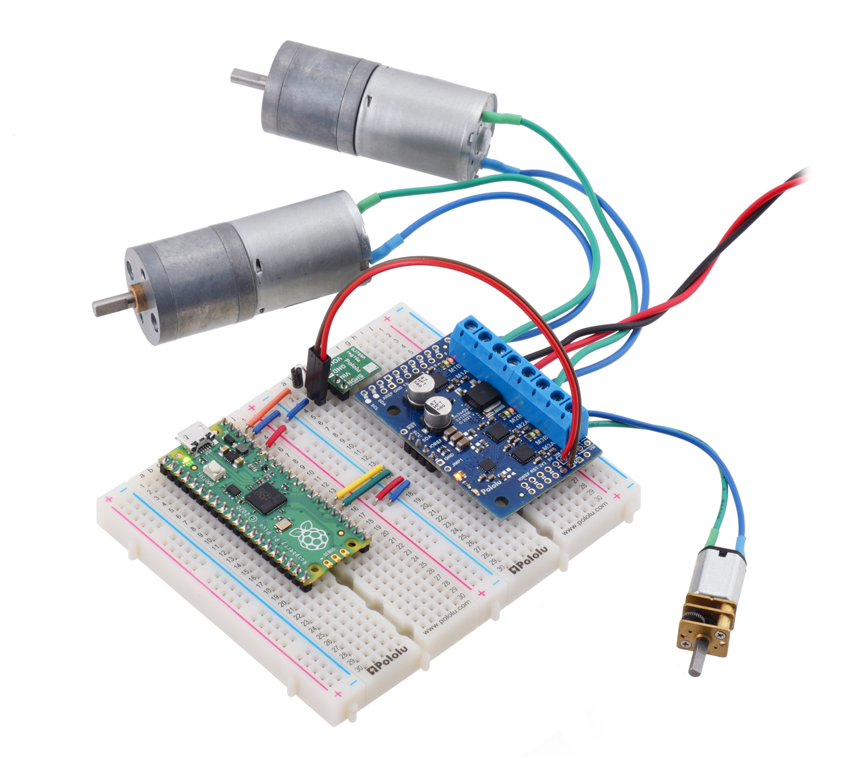 |
A Raspberry Pi Pico on a breadboard using a Motoron M3S256 shield to control three motors. |
|---|
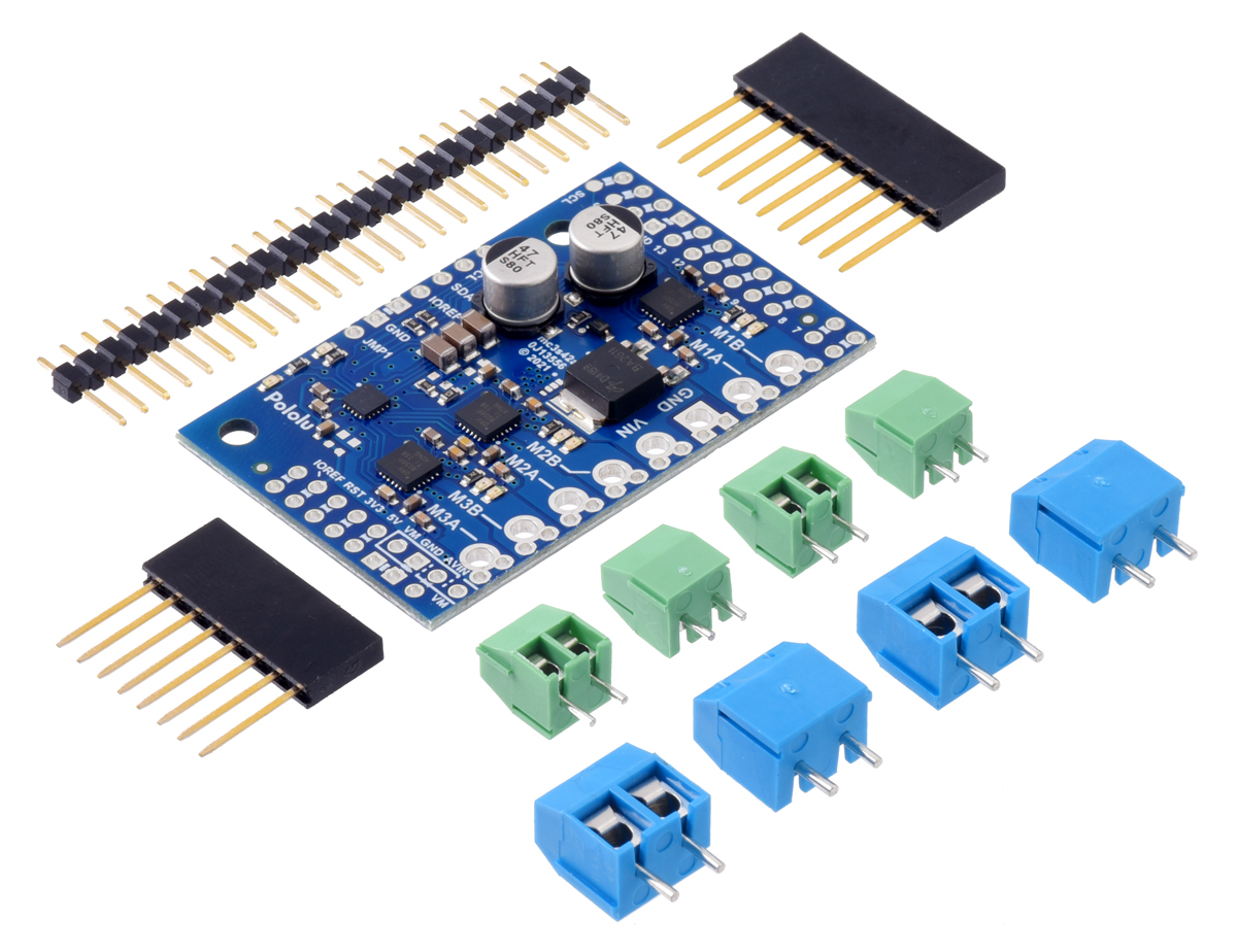
The Motoron M3S256 is available in three versions with different connector options:
- soldered with stackable headers and terminal blocks
- as a kit with connectors included but not soldered
- as a board only with no connectors included
|
|
|
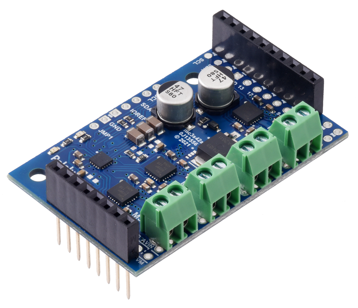

You might wonder why the assembled version comes with 3.5mm-pitch terminal blocks soldered in when the through-holes are spaced 5 mm apart. The answer is that the smaller 3.5 mm terminal blocks allow for more clearance when the shields are stacked, reducing the risk of shorting them to each other, but we still designed the board with bigger holes and wider spacing for maximum flexibility.
 |
For more information about the Motoron M3S256, see the product pages and the comprehensive user’s guide. We have plans to expand the Motoron family with more versions including Raspberry Pi-compatible form factors and higher-power models, so expect more announcements soon!
Related products


The Zumo gets a graphical display too: new Zumo 32U4 OLED Robot!
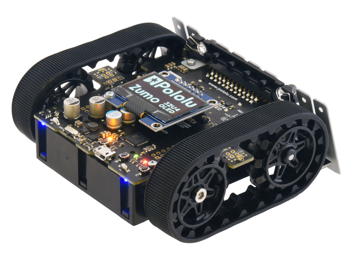 |
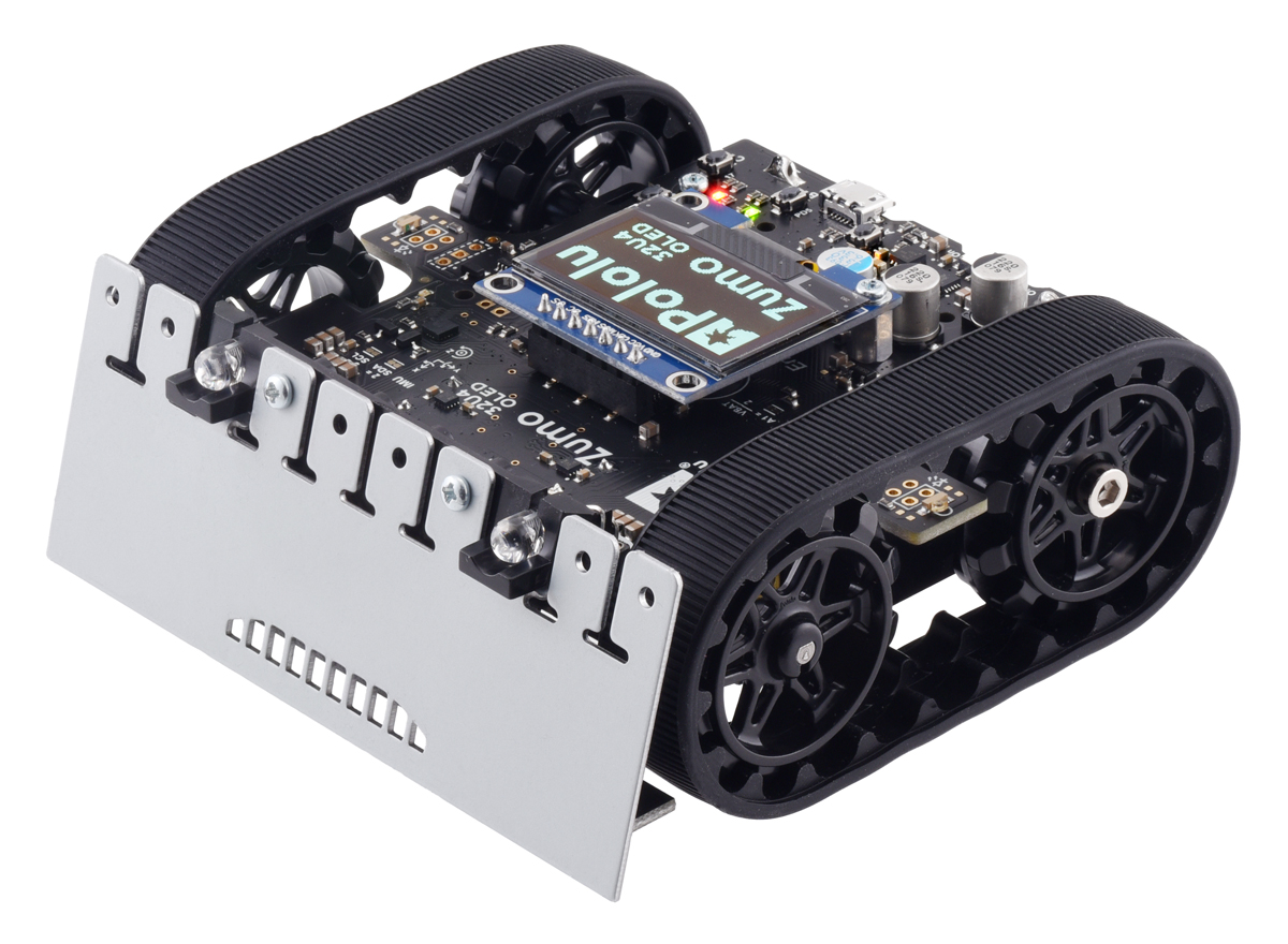
Our 3pi+ 32U4 robot got an upgraded OLED display earlier this year, and now it’s the Zumo’s turn with the release of our new Zumo 32U4 OLED Robot!
 |
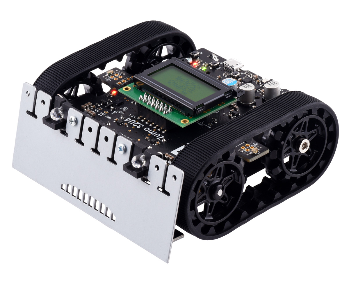
In many ways, this new version is just like the original Zumo 32U4: it’s a versatile tracked robot designed to be a capable Mini-Sumo competitor, but with enough sensors and extra features to enable lots of other applications. The Zumo 32U4 OLED adds to that versatility by replacing the original LCD (liquid crystal display) with a high-contrast graphical OLED display. With this monochrome 128×64 screen, you can present high-density data displays to help you analyze the Zumo’s status and sensor readings, or you can add some flair to your Zumo by showing eye-catching graphics.
We’ve updated our Arduino library for the Zumo 32U4 to add OLED display support as well as an LCD compatibility layer (the same way we did for the 3pi+), letting you easily convert existing programs to run on the OLED version or write new programs that will work on both old and new robots.
As with the LCD version, the new Zumo 32U4 OLED robot is available as a kit (with motors not included so you can select your own to customize performance) or as a fully assembled robot with your choice of 50:1, 75:1, or 100:1 motor options
|
|
Related products


New 3pi+ 32U4 OLED Robot with graphical display!
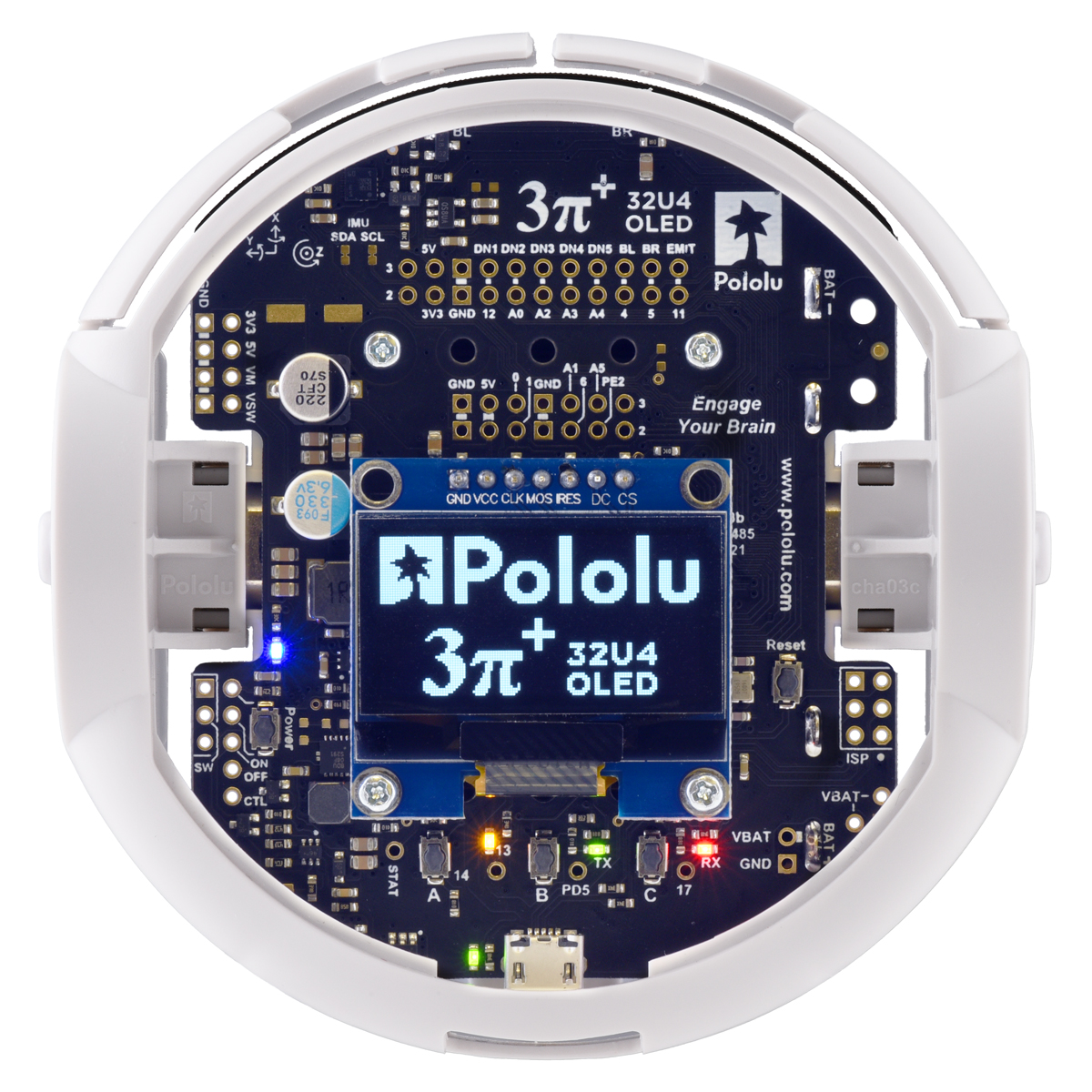 |
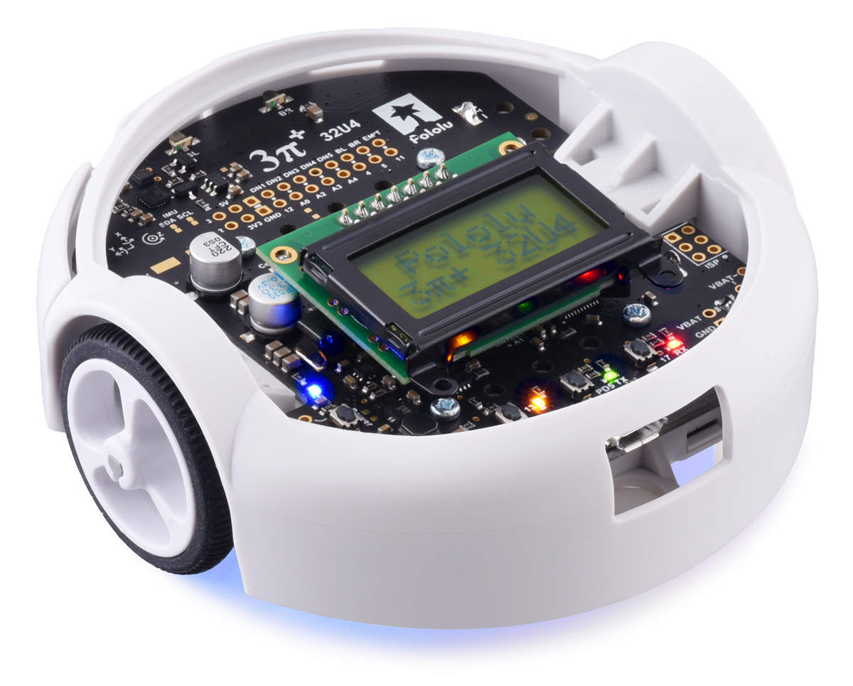
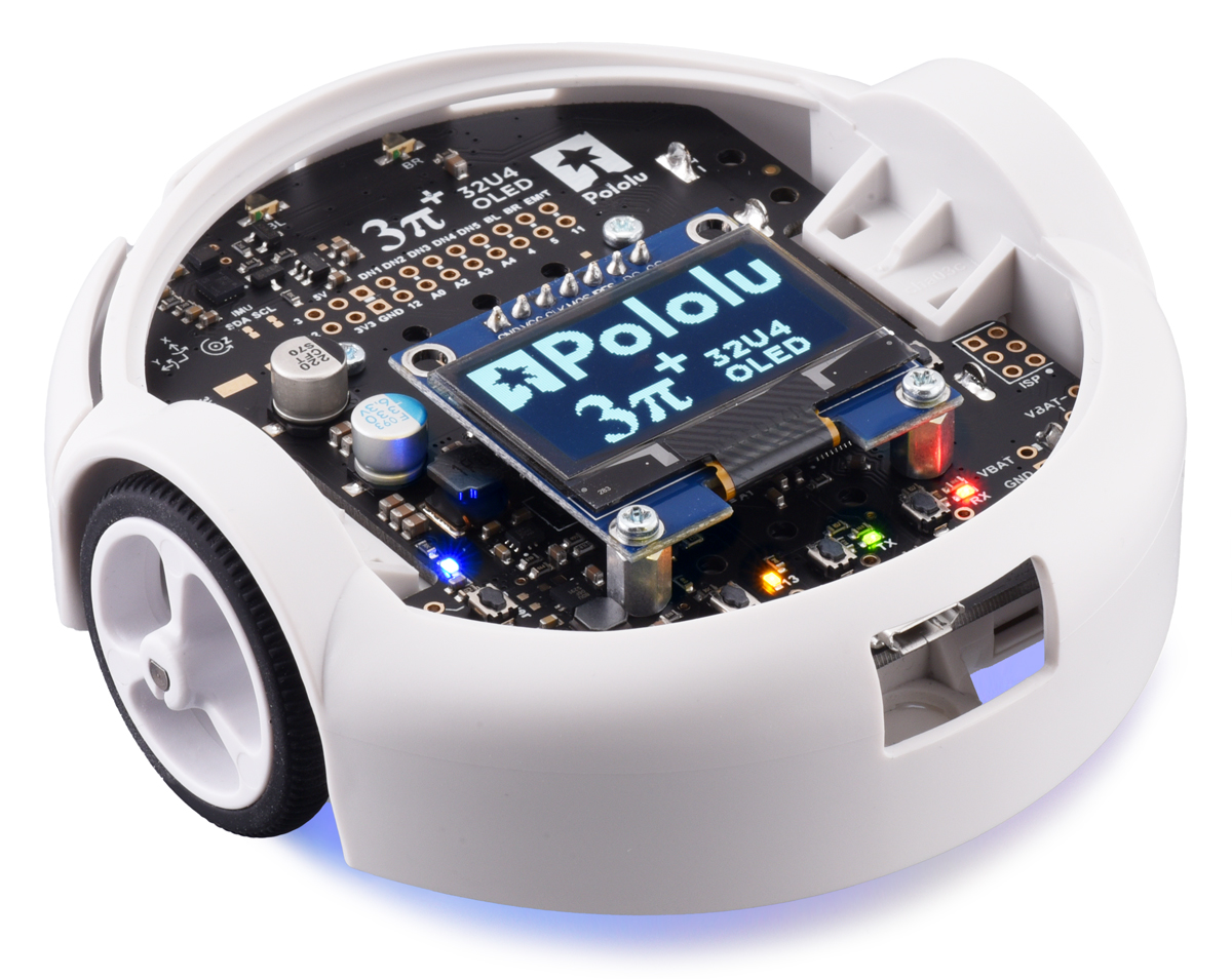
We are very excited to announce that the 3pi+ 32U4 OLED Robot is now available! This is an updated version of the original 3pi+ 32U4 Robot that replaces the old LCD with a monochrome 128×64 OLED display, giving it the ability to display fancy high-contrast graphics while following a line course, navigating a maze, or doing whatever it is that you want this compact but versatile mobile platform to do.
|
|
For more than 16 years, starting with some of our oldest products (from well before I joined Pololu), we have used HD44780-compatible alphanumeric liquid crystal displays on our robots and robot controllers. These LCDs have been around forever and are limited to displaying simple text on a fixed grid, but they are also ubiquitous: there are plenty of manufacturers still making displays that use the standard HD44780 interface.
 |
Pololu Orangutan Robot Controller connected to an AVR ISP (serial version). |
|---|
It’s unlikely that we would have much difficulty sourcing this kind of display any time soon (as long as the pandemic doesn’t mess things up too badly), so using them in our products has always been a safe option despite their graphical limitations. The original 3pi+ 32U4 that we released late last year was our most recent design to include LCD support.
Meanwhile, monochrome organic light-emitting diode (OLED) displays have become increasingly popular in electronics over the last decade or so, and it’s not hard to see why: you can draw graphics on them, they can fit more information on the screen, they’re easier to read in the dark, and they just plain look cooler. But even though you might be able to go to eBay or Amazon and order a cheap OLED display for your project when you want one, it’s critical that we find a dependable supplier for a component like this before we can start to design it into our products.
That is why the availability of the 1.3″ OLED module we announced recently was actually a pretty big deal for us: it means that we finally have a source that we can rely on for larger quantities of these displays. The 3pi+ 32U4 OLED is the first of what we hope will be many robots and control boards that make use of the graphical capabilities offered by an OLED screen.
 |
Like the original 3pi+ 32U4, the newer OLED version is available with three different motor options, either fully assembled or as a kit:
| 3pi+ 32U4 OLED Version | Products | Micro Metal Gearmotor | Top Speed | Comments |
|---|---|---|---|---|
| Standard Edition | assembled or kit | 30:1 MP 6V | 1.5 m/s | good combination of speed and controllability |
| Turtle Edition | assembled or kit | 75:1 LP 6V | 0.4 m/s | longest battery life, easiest to control, good for swarm robots or introductory robotics courses |
| Hyper Edition | assembled or kit | 15:1 HPCB 6V | ~4 m/s | very fast and difficult to control, easy to damage; only recommended for advanced users |
For anyone who wants to use different motors than the options above, the 3pi+ 32U4 OLED control board is likewise available separately and can be combined with a 3pi+ chassis and a pair of motors to build a custom robot.
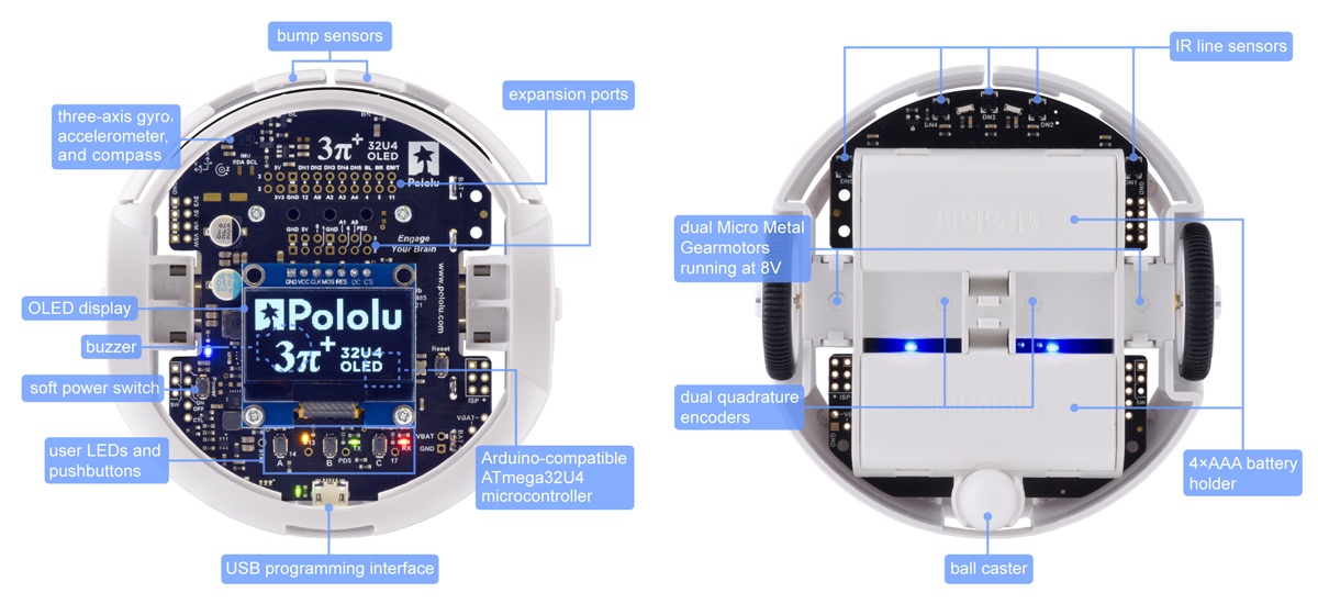
We will be phasing out the original 3pi+ 32U4 robots and kits (they will remain available by special order), but that does not mean the old versions are suddenly obsolete or that you will have to learn an entirely new platform to use the new OLED version. Aside from the display interface, the hardware on the LCD and OLED versions is exactly the same, with features including encoders, line sensors, front bump sensors, and a full IMU (inertial measurement unit).
From a software perspective, it can actually be pretty challenging to work with graphics, especially on a small processor like the ATmega32U4. The simplicity of a text LCD can be an advantage in that you can essentially just ask it to do something like printing the letter “A” on the first column of the second row. On a graphical display, even if you just want to show some text, you have to define the shape of the letter in pixels; optionally composite that shape into a memory buffer; and then send the complete pixel data to the display. That means you have a lot more control over how that letter “A” is shown, but it takes a lot more work to do it.
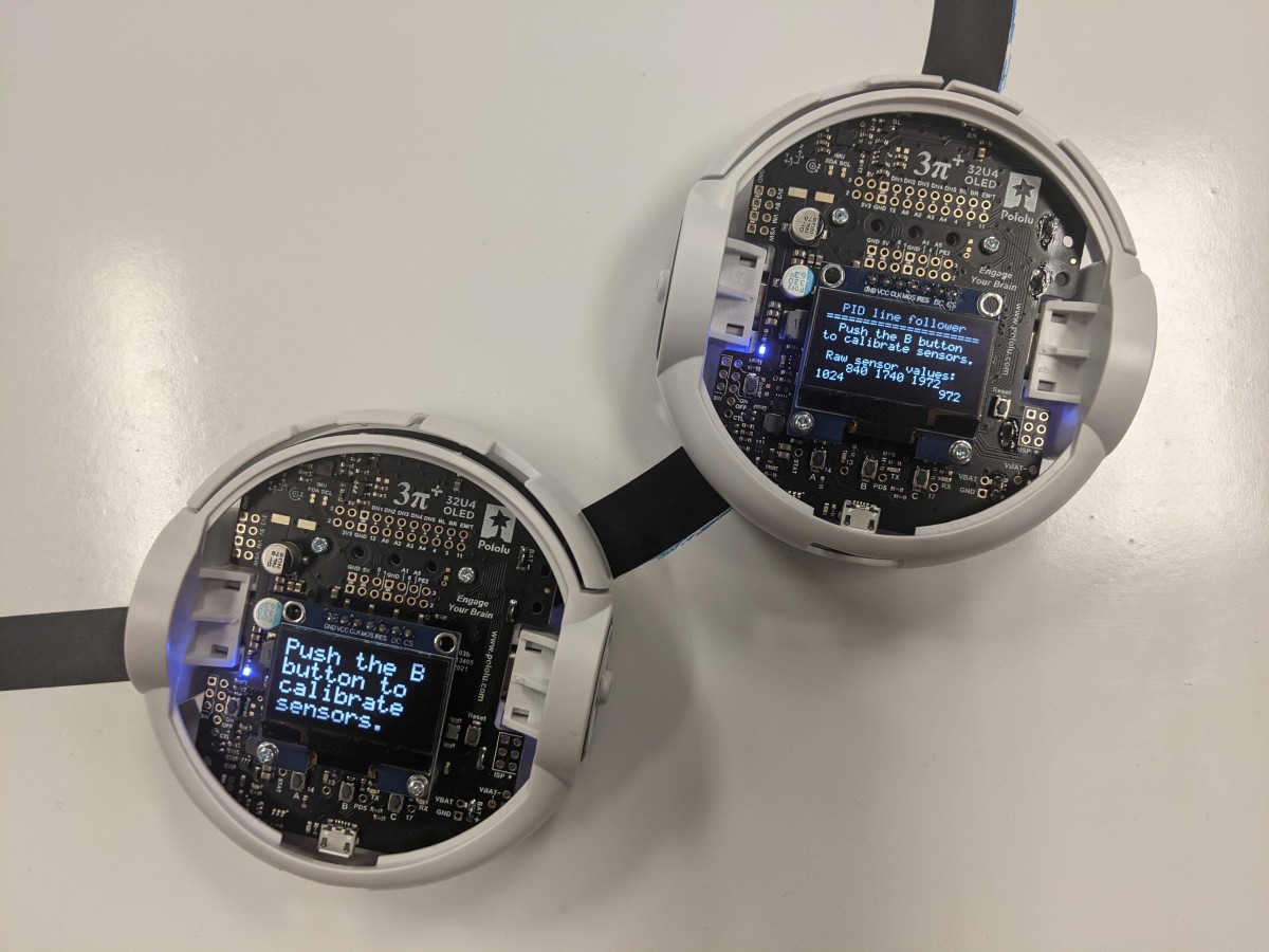
To help get you started, we’ve developed an LCD compatibility layer as part of our Arduino library for the 3pi+ 32U4. This makes it easier to use the OLED screen for common display tasks, and it’s straightforward to write programs that will work on either version of the robot with minimal changes, since you can update an existing program to run on the OLED version by changing just a single line of code.
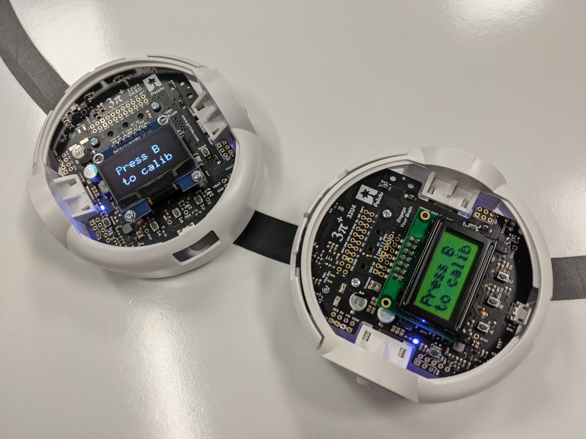 |
A 3pi+ 32U4 OLED and an original 3pi+ 32U4 running nearly identical programs and displaying the same text. |
|---|
Additionally, the same library makes it trivial to get the benefit of a higher-density text area: you can easily “upgrade” from an 8×2 character grid to an 11×4 or 21×8 layout.
 |
Higher-density text layouts on the displays of some 3pi+32U4 OLED robots. |
|---|
We plan to continue improving our libraries to give you more options for efficiently working with both text and graphics on an OLED display; stay tuned for updates!
|
|
|

Related products


Roll your own continuous Arduino testing with our new arduino-ci
 |
As I wrote a few years ago, we used to use Travis CI and PlatformIO to confirm our Arduino libraries and examples compile after every code change. This helps us maintain confidence in the quality of our code and makes it easier to release changes. Of course that’s not as good as the extensive testing with actual hardware that we also do, but it’s really great as a quick check that we haven’t completely broken anything.
Unfortunately, Travis CI doesn’t work for code in development that has not yet been put up on GitHub. That, combined with Travis CI limiting how many testing minutes you get each month for free and GitHub Actions existing as a free replacement for it, pushed me to make a new solution that works for us.
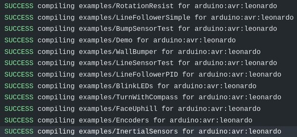
So, we made arduino-ci: a simple Ruby script that is super easy to use with the continuous testing solutions provided by GitHub and GitLab. It uses arduino-cli to install cores (bundles of code for specific Arduino board architectures), install library dependencies, and compile all the examples. By default, it compiles all examples for the following boards:
- arduino:avr:uno
- arduino:avr:leonardo
- arduino:avr:mega
- arduino:avr:micro
- arduino:avr:yun
- arduino:sam:arduino_due_x
- arduino:samd:arduino_zero_native
- Intel:arc32:arduino_101
- esp8266:esp8266:huzzah
You can use the configuration file to edit these defaults and add any additional library dependencies.
This isn’t the only Arduino continous testing program around. There’s also:
- arduino_ci (underscore not dash) – a much bigger Ruby project with features like C++ unit testing and mocks
- ci-arduino (are you seeing the pattern of confusing names yet?) – Adafruit’s testing program written in Python with features like Doxygen integration and code formatting
Sorry about the names, really! In contrast with these, arduino-ci is a very small program that focuses on compiling Arduino libraries and examples.
We are using arduino-ci for all of our libraries, and it should work for any Arduino Library, so if you have one, please try it out and tell us what you think! For more information, please read the arduino-ci readme.
Our newest robot, 3pi+, is here—Arduino-compatible, USB, encoders, full IMU and more!
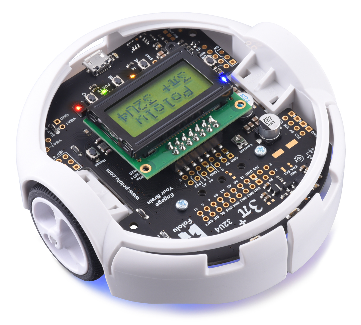 |
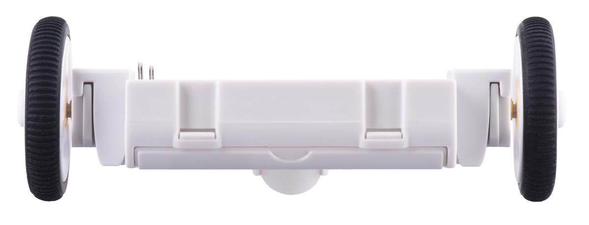
I am thrilled to announce the release of our newest robot, the 3pi+! This new platform is a major upgrade from the original 3pi robot we introduced twelve years ago. At 97 mm, the diameter is just 1mm larger than the original, and the general concept of a tiny, fast robot powered by four AAA batteries and two micro metal gearmotors remains the same. However, just about everything has been redesigned from the ground up to add the extra features everyone has been asking for.
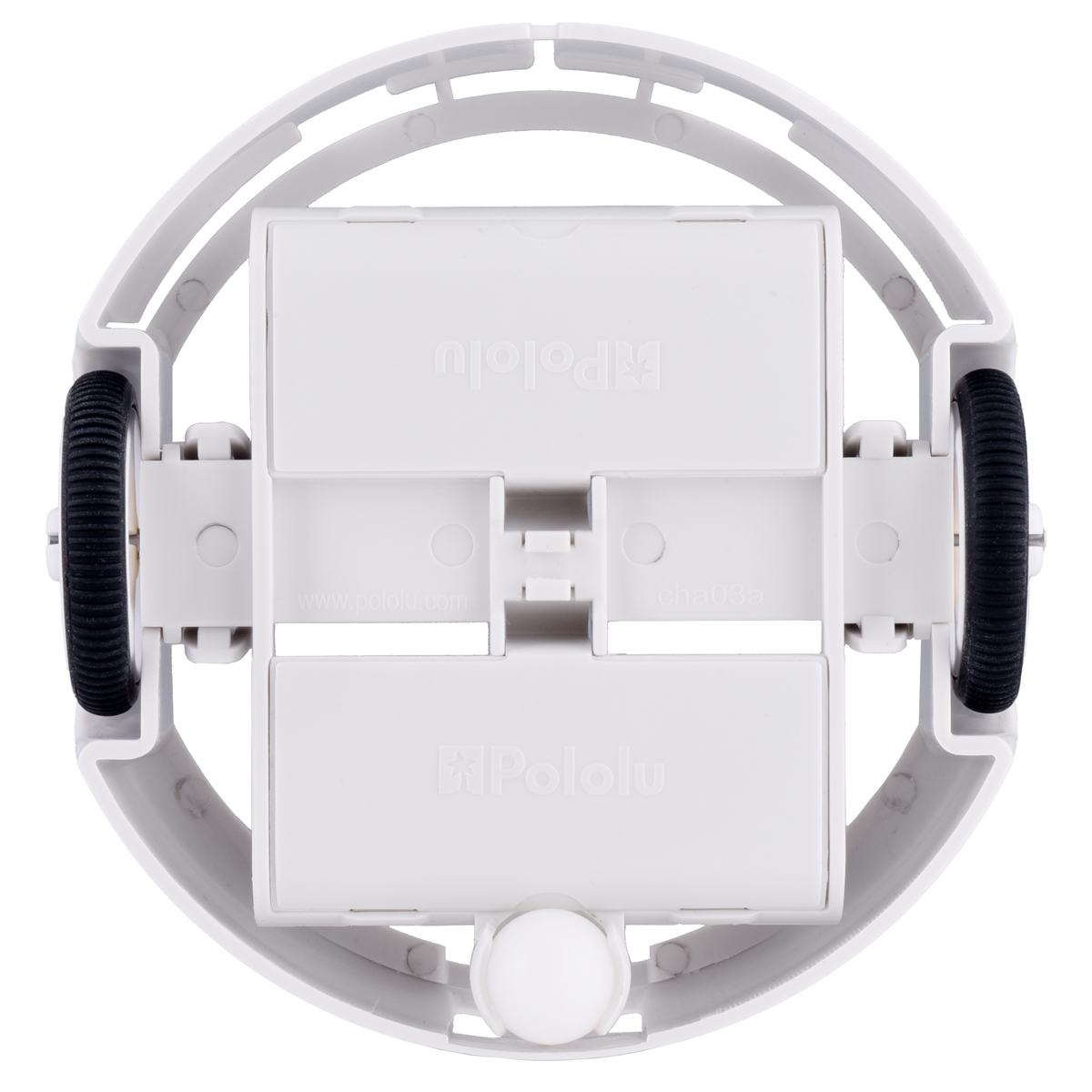
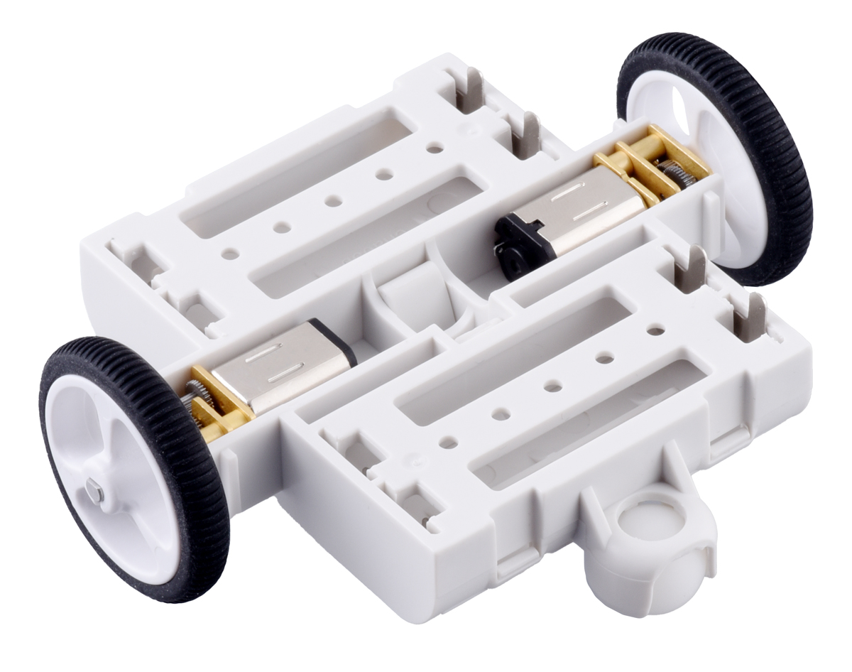
First off, the 3pi+ is now a platform that encompasses a range of products, not just one particular robot. This is enabled primarily by the chassis now being an independent structure rather than being a specific circuit board with motors strapped on:
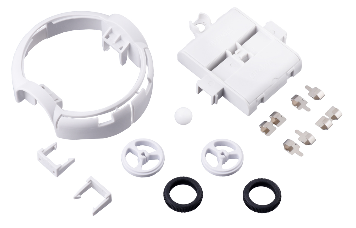 |
3pi+ Chassis Kit (No Motors or Electronics). |
|---|
|
|
|
|
|
|
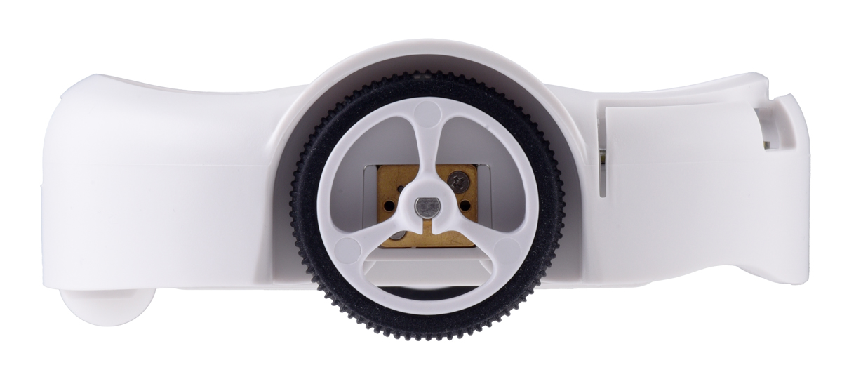

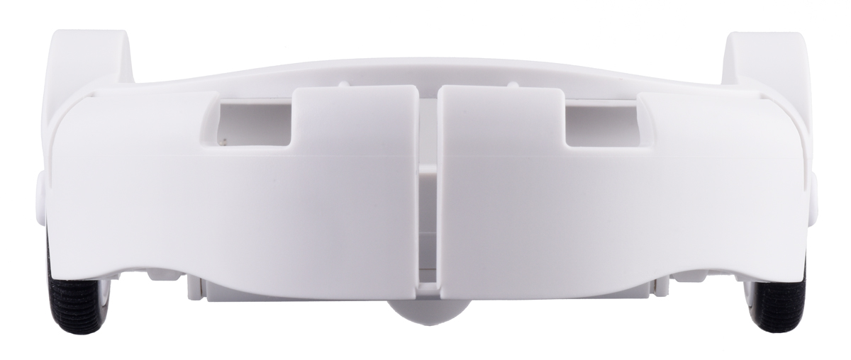
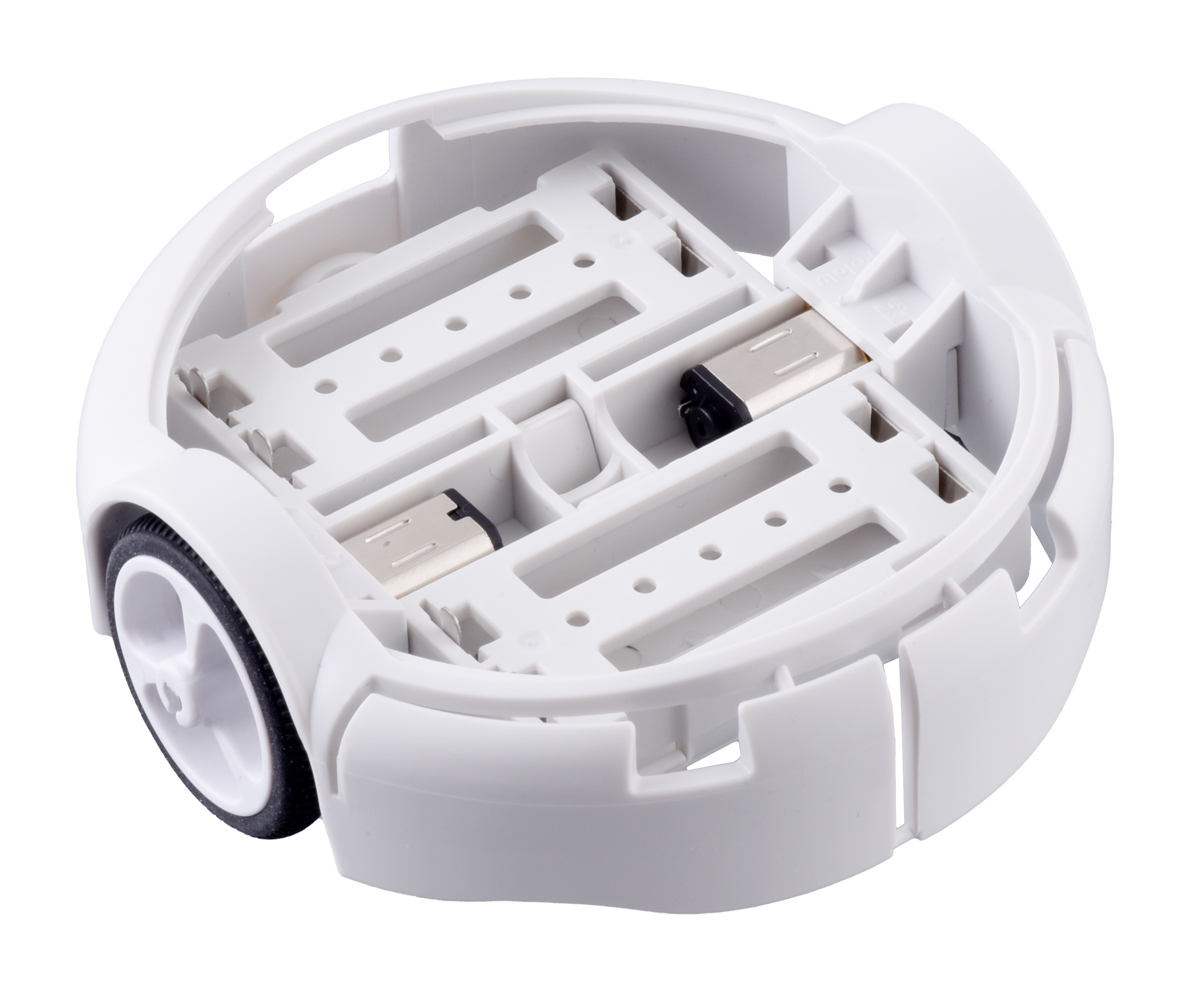
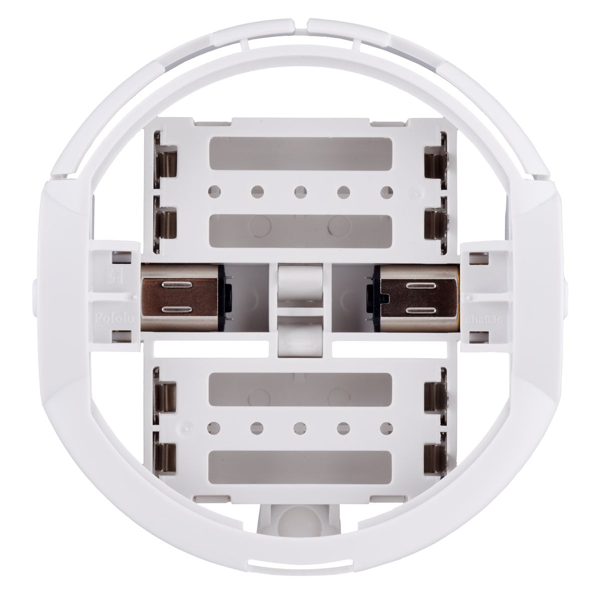
The chassis incorporates the battery holders, motor mounts, and ball caster. An outer bumper skirt is removable and the motors can instead be held in by separate clips (also included in the kit). The left-most picture shows the chassis with motors installed but without the bumper skirt or motor clips, and the next two pictures show the motor clips installed:
|
|
|
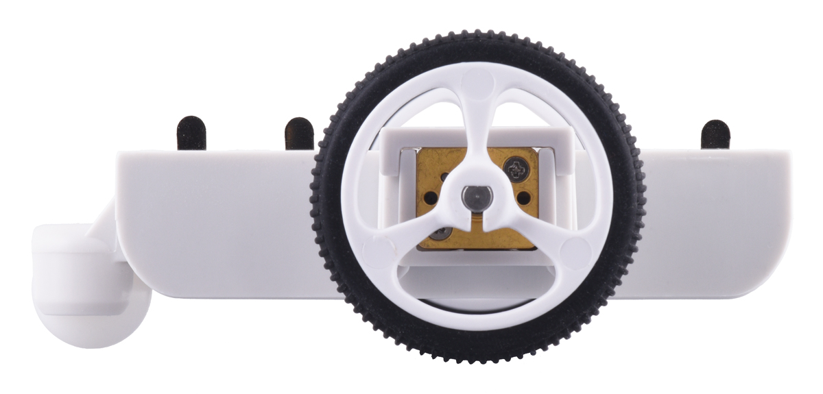
Making the chassis separate from any electronics means that you can use it with your own electronics and that we can make various versions with different capabilities and microcontrollers.
3pi+ 32U4
The first full 3pi+ robot we are launching is the 3pi+ 32U4, which is based on an Arduino-compatible ATmega32U4 microcontroller from Microchip (formerly from Atmel). Like the original 3pi, the 3pi+ 32U4 has five integrated downward-looking reflectance sensors, making the robot a great starting point for line following and line-maze events.
The 3pi+ 32U4 offers many major improvements over the original 3pi, including:
- ATmega32U4 microcontroller with Arduino-compatible bootloader can be programmed directly through a USB connection
- Quadrature encoders on both motors for closed-loop position and speed control
- Full 9-axis IMU (three-axis gyro, accelerometer, and compass)
- Bottom-loading battery holders keep batteries accessible even if additional levels are added
- Full wrap-around bumper to protect electronics from collisions
- Two bump sensors on the front
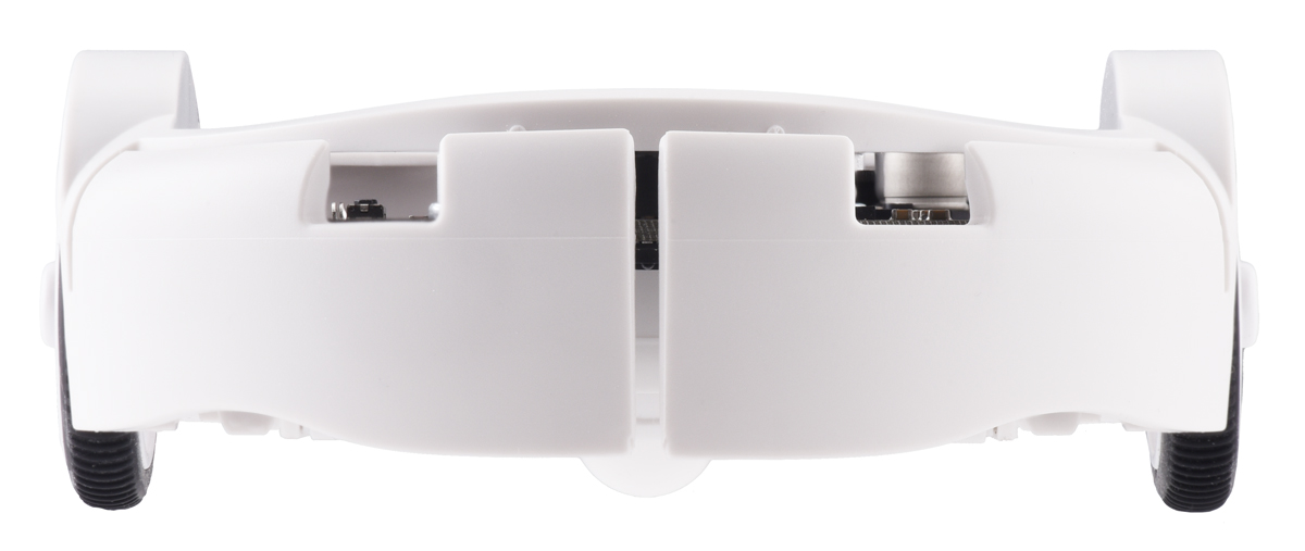
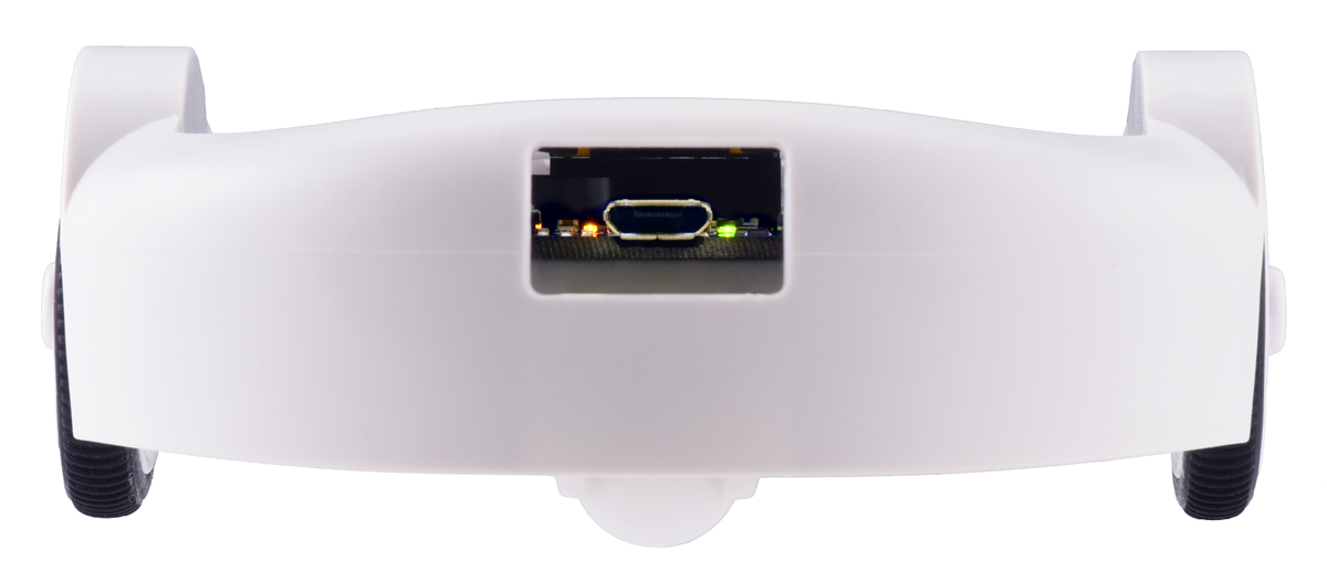
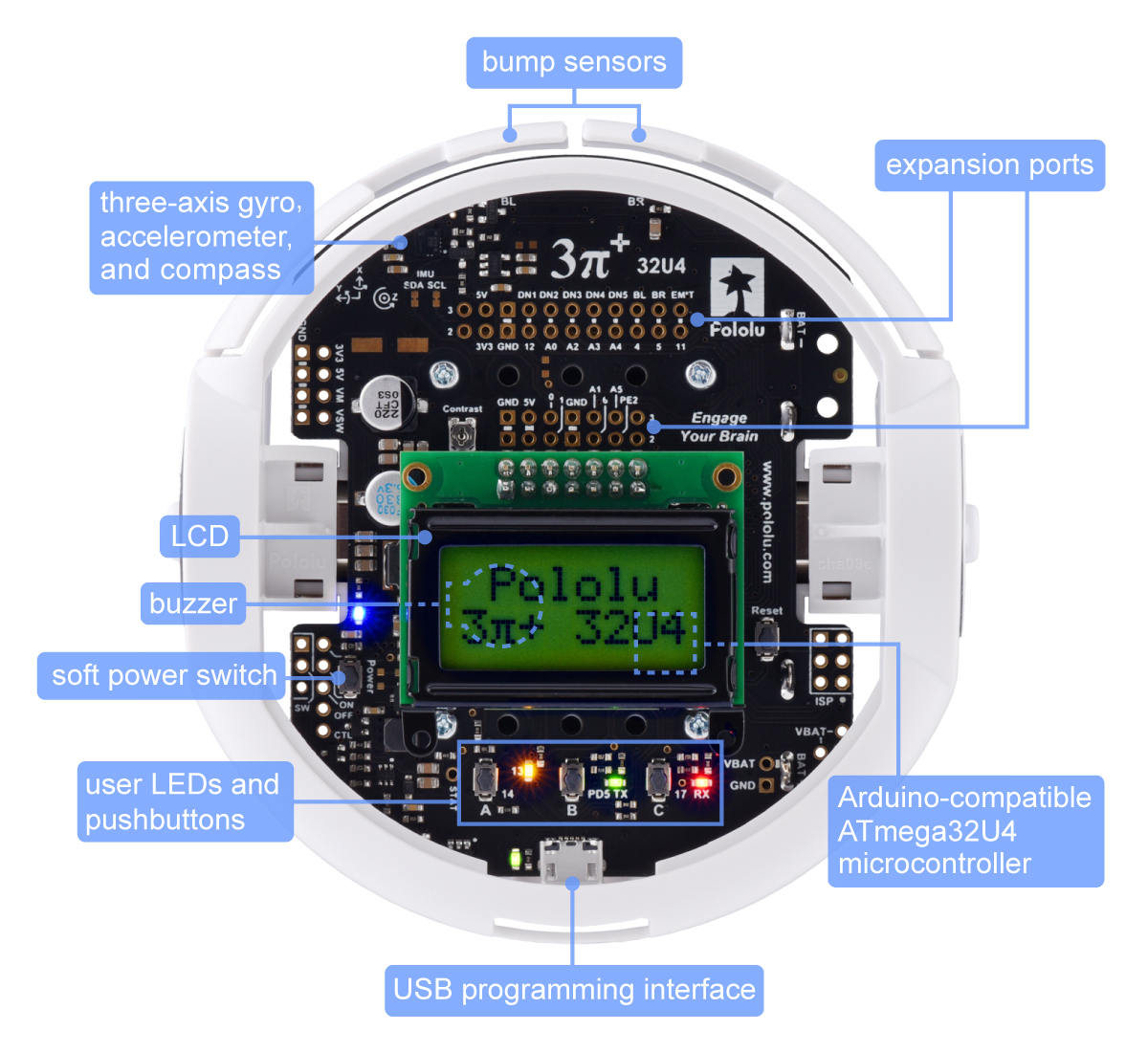 |
3pi+ 32U4 Robot features, top view. |
|---|
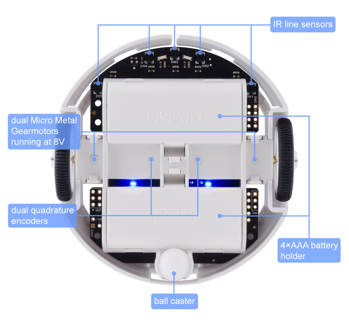 |
3pi+ 32U4 Robot features, bottom view. |
|---|
The 3pi+ 32U4 is also available with three motor options for different usage scenarios:
| 3pi+ 32U4 Version | Products | Micro Metal Gearmotor | Top Speed | Comments |
|---|---|---|---|---|
| Standard Edition | assembled or kit | 30:1 MP 6V | 1.5 m/s | great all-around balance between controllability and speed, with top theoretical speed above that of the original 3pi |
| Turtle Edition | assembled or kit | 75:1 LP 6V | 0.4 m/s | longest battery life, easiest to control, appropriate for swarm robot projects or classrooms where you might not want robots flying around the floor (or desktop) too quickly |
| Hyper Edition | assembled or kit | 15:1 HPCB 6V | ~4 m/s | ridiculous speed, which can definitely be fun. But, controlling that speed can be difficult, which can make the robot more prone to self-destruction (or at least self-inflicted damage), so we recommend this only for advanced users |
These three 3pi+ 32U4 motor options are available in assembled or kit form, and for those who want to do your own thing, the parts are available separately so that you can pick some other motor or gear ratio.
Normally we would have an introductory special for this big of a new product release, but since we are about to launch our annual Black Friday and Cyber Monday sale, you can get a great discount on the new 3pi+ there!

Related products


Updated product: A-Star 32U4 Prime LV
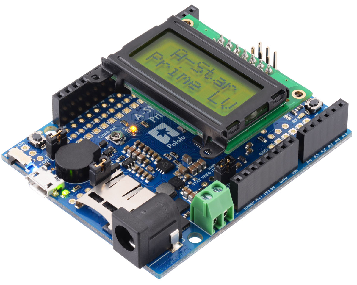
We have updated our A-Star 32U4 Prime LV with a new regulator that offers a wider operating voltage range and increased current capabilities. For those of you not already familiar with our A-Star 32U4 Primes, they are a series of ATmega32U4-based, USB-programmable controllers with integrated regulators that offer operating voltage ranges not available on typical Arduino-compatible products; this new “LV” variant features an improved buck-boost converter that enables efficient operation from 2 V to 16 V power supplies (Note: it requires an input voltage of at least 3 V to start, but it can operate down to 2 V after startup). The A-Star Primes are arranged in the common Arduino form factor exemplified by the Uno R3 and the Leonardo, so they are compatible with many Arduino shields, including all of the Arduino shields we carry.
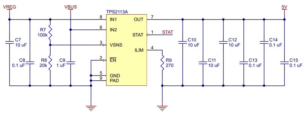
In addition to the increased input voltage range for the new A-Star Prime LV, the new regulator also provides more current. The graph below shows the current available on the new LV (ac03e) in blue compared to the old LV (ac03b) in purple. It is important to note that to use the full current available on the new A-Star Prime LV, you must connect to the VREG pin on the board and not the 5V ouput pin. The 5V output pin is limited to about 1.9 A because of the TPS2113A power multiplexer that makes up the board’s power selection circuit (a feature that sets the A-Star Primes apart from competing products). The power multiplexer decides whether the board’s 5 V supply is sourced from USB or an external supply via the regulator, allowing both sources to be connected at the same time and enabling the A-Star to safely and seamlessly transition between them. The multiplexer is configured to select external power unless the regulator output falls below about 4.5 V. If this happens, it will select the higher of the two sources, which will typically be the USB 5 V bus voltage if the A-Star is connected to USB. More information about the multiplexer can be found in this section of the A-Star 32U4 user’s guide under the Power heading.
|
|

The original version of the A-Star Prime LV, which operates from 2.7 V to 11.8 V, is now on clearance for 40% off! If you don’t need the increased output current and wider voltage range the new board offers, the previous version is still a great programmable controller to consider. Both the new and original A-Star Prime LVs come in multiple configurations. The complete selection of both versions can be found in the related products list below.
Related products


Modified Han Solo toy blaster controls LED displays of Star Wars characters
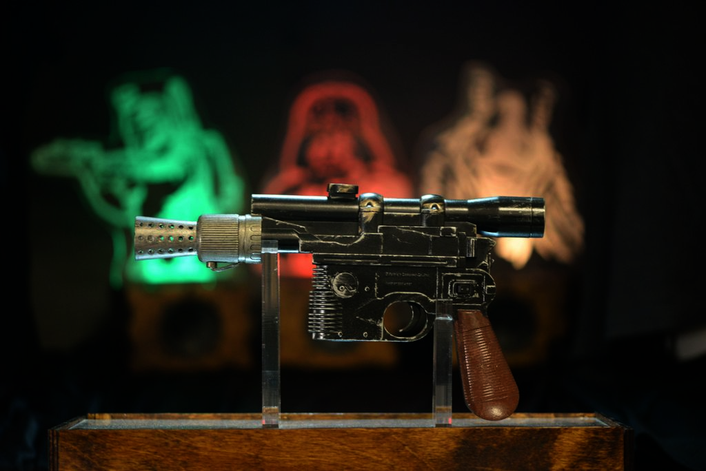 |
A while ago, I made a wedding gift for some friends, both of whom are avid Star Wars fans. The gift was basically a multi-piece decorative set that consisted of a modified toy Han Solo blaster, a stand to hold the blaster, and three edge-lit LED displays: one each of Boba Fett, Darth Vader, and Jar Jar Binks. I painted over the toy blaster to make it look more like it came straight out of the movies and added electronics so that it could interact with the displays (and the couple’s TV!).
The blaster uses IR TV remote codes to do several things: it can shoot the LED displays (and they’ll respond by blinking and playing audio recordings unique to each character), change the color and brightness of each display, and it can act as a limited TV remote by turning on or off the TV. At the heart of the blaster lies an A-Star 32U4 Mini ULV, which monitors the state of a switch, a couple of buttons, and a few potentiometers in order to decide which actions to carry out. The ULV version of the A* Mini is especially convenient for this setup because the toy blaster was originally powered by two AAA batteries, which produce too low of a voltage for a 5V microcontroller. The ULV’s built-in switching step-up voltage regulator allows it to operate directly off of the batteries and power the other components, unlike typical Arduinos that need at least 7V.
|
|
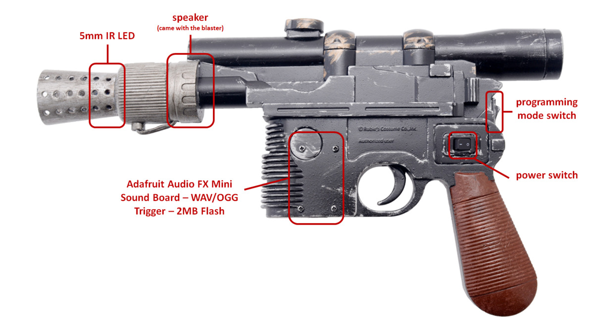
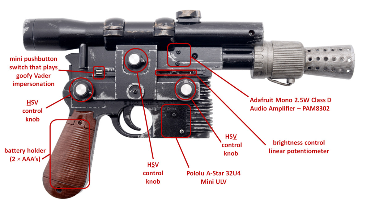
The blaster has two modes: one for shooting the displays and turning on/off the TV and another for adjusting color and brightness of the displays. Which mode the blaster is in is determined by the state of the programming mode switch, which is accessible with a flick of the thumb. While powered on, the A* continually checks to see if the programming mode switch is enabled. If it is disabled, the blaster will respond to trigger presses. When the trigger is depressed, the A* does two things: it sends a pulse train to a 5mm IR LED and drives an input pin low on an Adafruit Audio FX Mini sound board, which then outputs sound to a speaker through a 2.5W audio amplifier, producing DL-44 blaster firing noises. The blaster and displays use the IRremote Arduino library for sending and receiving the pulses. For these blaster shots, the blaster emits the IR TV remote code that corresponds to the generic power-on/power-off code for an LG TV. This same code is decoded by the Star Wars displays as a “hit” and the characters react to being shot. You can watch videos of those reactions in the YouTube playlist below (the playlist also includes the displays’ bonus Easter egg content, which is only accessible by sending certain button presses from the LG TV remote!). The sound level is a little low, so you might need to increase your volume to hear what the characters are saying:
If the programming mode switch is enabled, the blaster repeatedly emits a set of IR TV remote codes that contain information on what color and how bright the displays should be. Color is adjusted in the HSV color space using the blaster’s three rotary potentiometers (one each for hue, saturation, and value). There is also a linear potentiometer that can be used to set overall brightness (this effect combines with the change in brightness from adjusting the value potentiometer). So long as a display’s IR receiver can detect the IR signal sent by the blaster, the LED information can be decoded and the LED arrays can be updated.
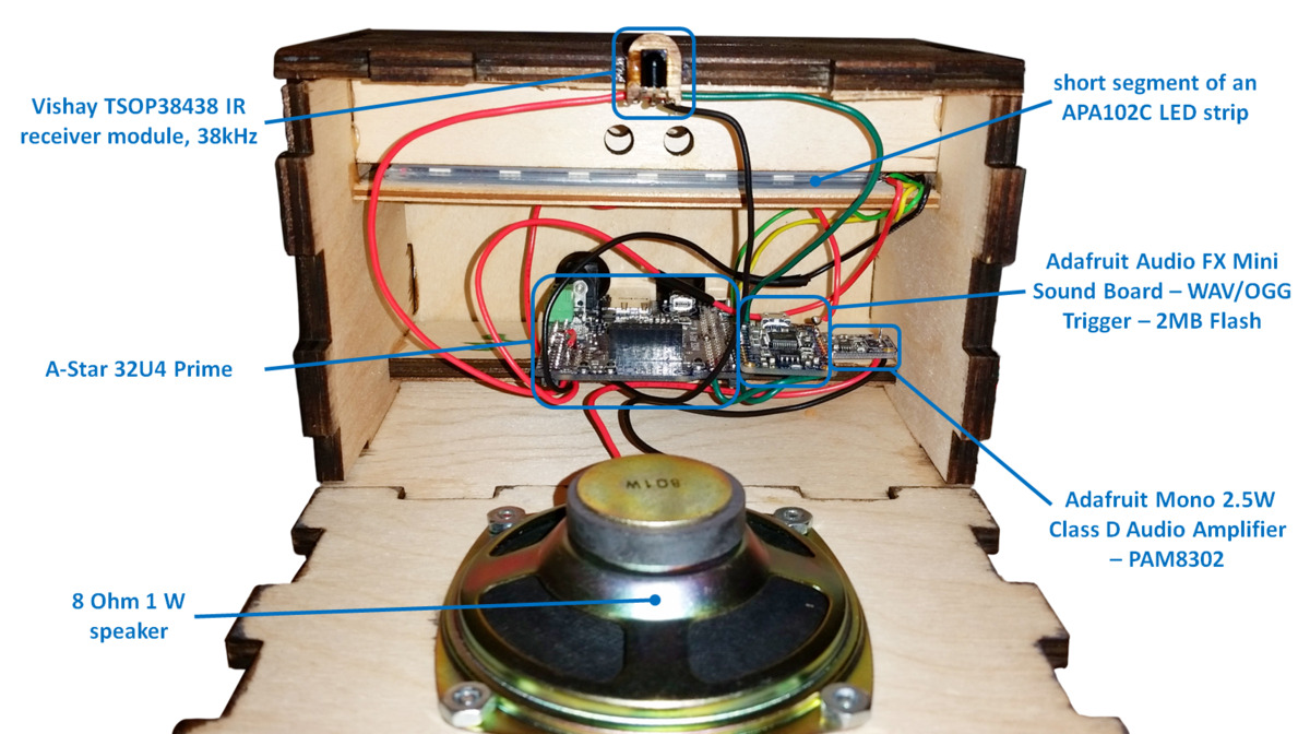
 |
Each display features a ~12″ tall profile of the head or upper body of a Star Wars character. The profiles are laser-etched onto a 1/2″ thick clear acrylic piece, which also has holes at its base. The holes allow the piece to be fastened to a recessed channel at the top of the display box. A short segment of an APA102C LED strip lines the bottom of the recessed channel and faces upward into the acrylic profile, which allows its light to disperse across the laser-etched surfaces. The display box has the same sound board and amplifier as the blaster, but uses a more powerful 1W speaker. An A-Star 32U4 Prime controls everything and power is supplied via a 9V 3A wall power adapter.
 |
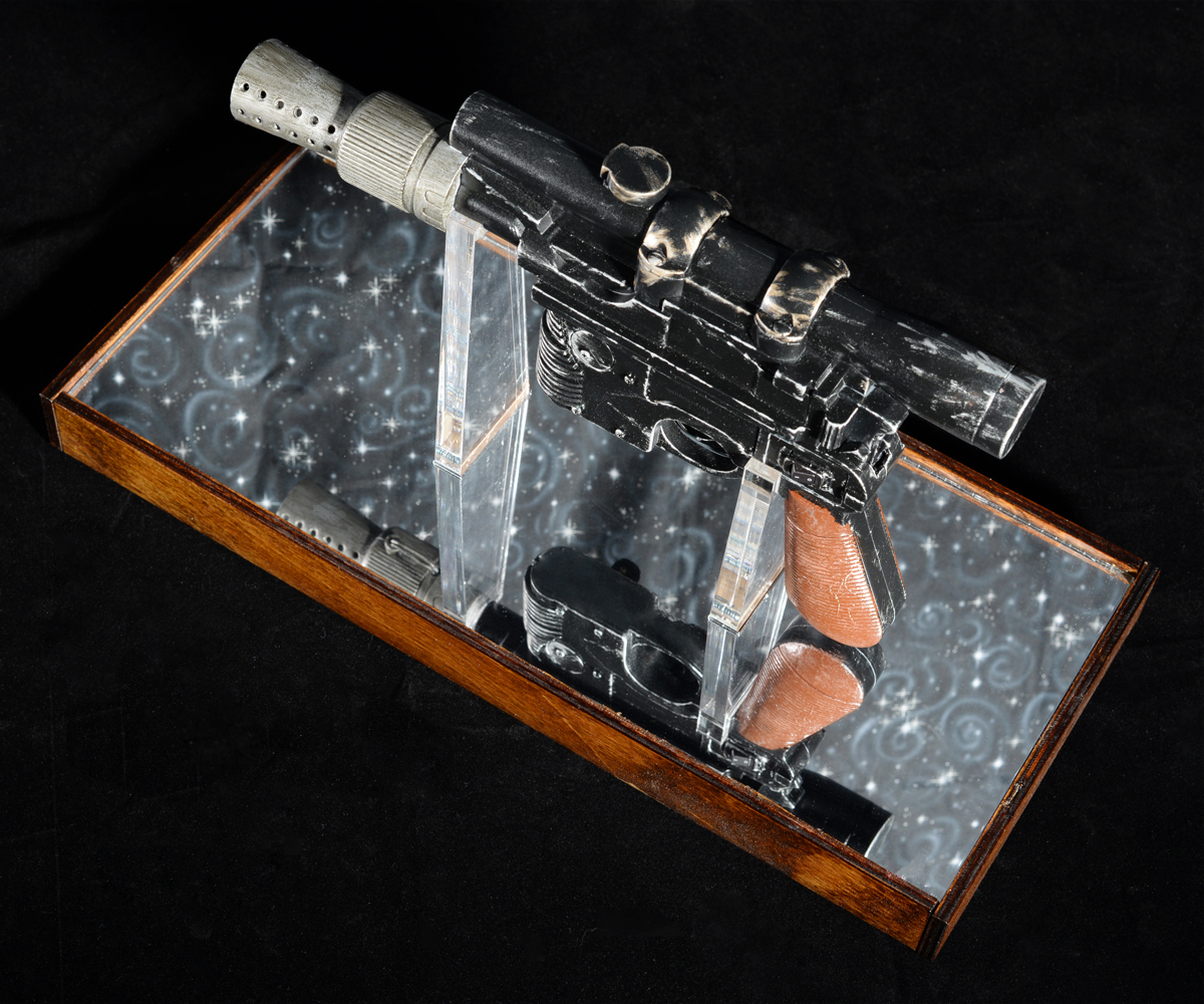
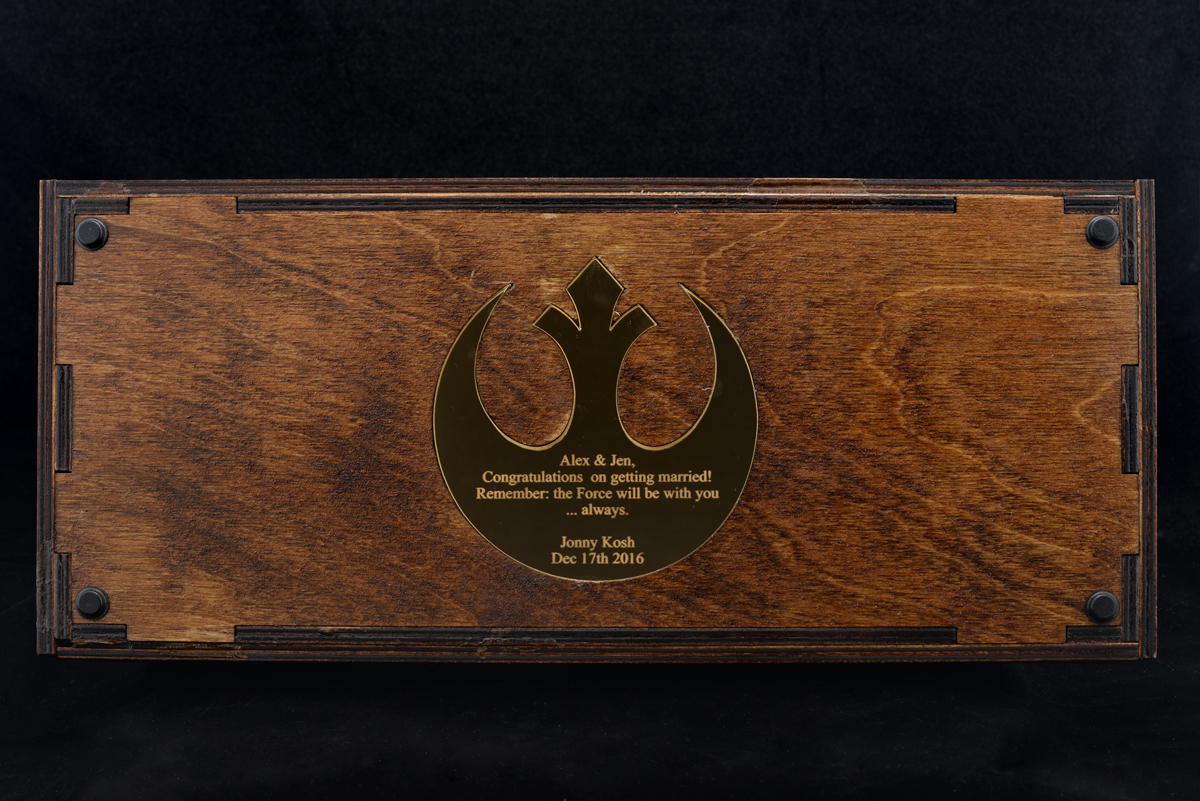
Compared to the rest of the system, the design of the blaster stand is pretty straightforward: it is just several pieces of 1/4″ plywood arranged into a frame that houses two channels. Those two channels have mounting holes which allow two clear acrylic pieces, which conform to the shape of the blaster, to be fixed to the frame. A lip along the inside of the frame makes it easy to mount the silver mirrored acrylic piece. The bottom of the mount features a personal well-wish from me to the couple. The message is written on the inside of the Alliance Starbird, which is cut from gold mirrored acrylic. The stand also houses some scrap metal parts (a bunch of prototype Zumo blades) to give it some weight. Four adhesive rubber feet, one for each corner of the stand, help make sure the stand doesn’t slide around easily and scrape the gold Starbird piece.
|
|
I owe a part of the inspiration of this gift to my coworker, Kevin, since in some ways I was basically trying to one-up his Harry Potter-themed wedding gift, which was given to another coworker, Brandon, for his wedding. Kevin also ended up helping me make some good decisions and generate some clean-looking CorelDraw files for the display cutouts/rastering. So, thanks, Kevin! You the real MVP.
For more pics, gifs, and a build log, check out this Imgur album! Also, you can find 2D (.DXF and .CDR) and 3D (.STL, .STEP, and .SLDPRT) CAD files for the laser cut parts on my Thingiverse page!
 |
Related products


Now available: VL53L1X library for Arduino
We’ve released a basic VL53L1X library for Arduino to make it easier to get started using an ST VL53L1X time-of-flight distance sensor with an Arduino-compatible controller.
Because of how complex the VL53L1X is and how difficult it is to learn how it works, developing a library for it has been more of a challenge than writing one for a typical sensor like an LSM303 accelerometer/magnetometer. Continued…
New products: Dual MAX14870 Motor Drivers for Arduino and Raspberry Pi
For my birthday, I am excited to share two new products to help get your projects moving: dual motor driver boards for Arduino and for Raspberry Pi based on Maxim MAX14870 drivers, which on these boards (without additional cooling) can power motors with a continuous 1.7 A (2.5 A peak) from a voltage source anywhere from 4.5 V to 36 V. This makes the driver ideal for powering a wide range of motors including our high power micro metal gearmotors, and our 12 V 20D mm metal gearmotors. We like the MAX14870 so much that already we make a single driver carrier for it, and we use it on our A-Star 32U4 Robot Controller SV. These new boards make it easy to control two motors using the MAX14870 with an Arduino or Raspberry Pi.
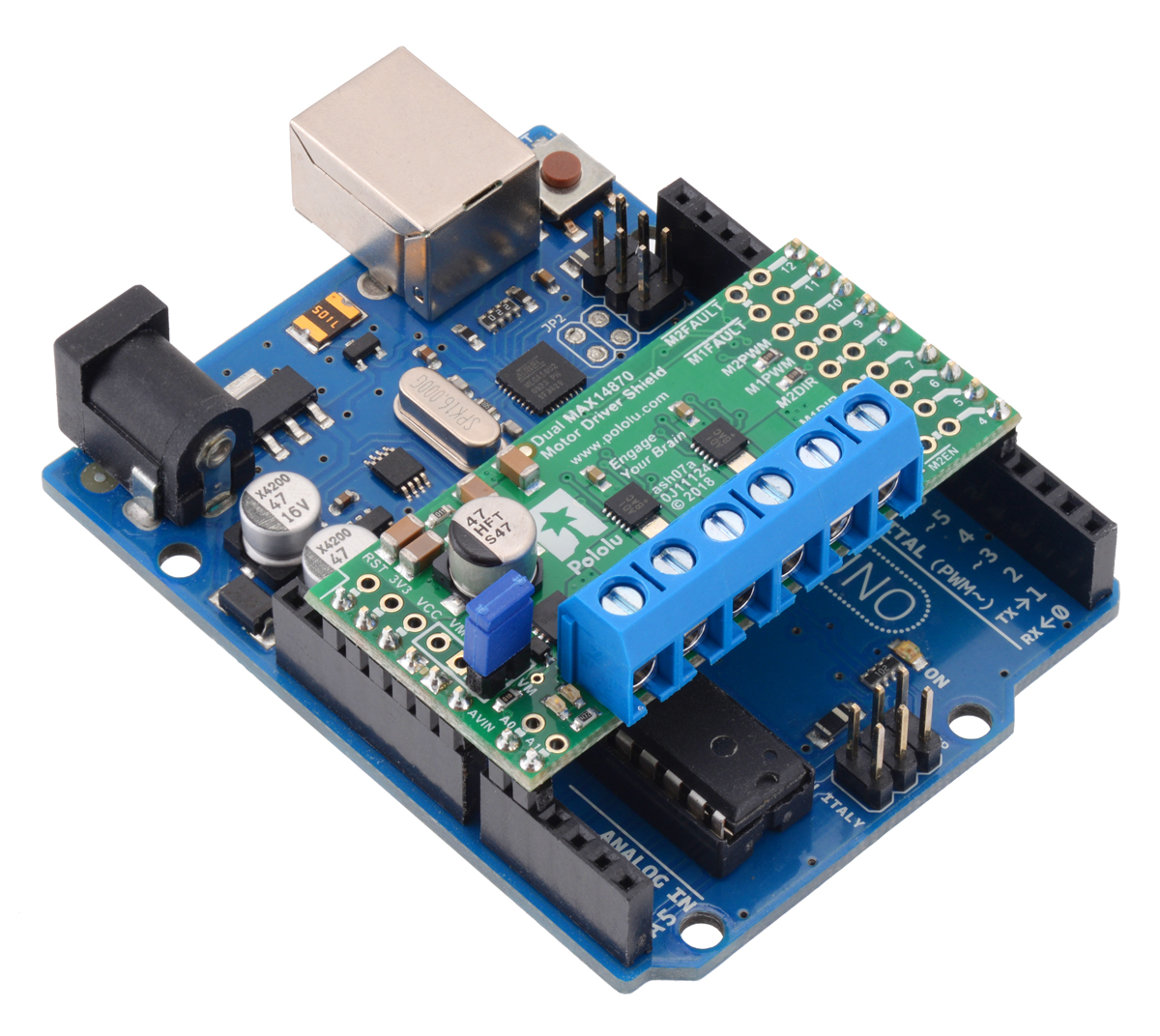 |
The Dual MAX14870 Motor Driver Shield for Arduino is designed to plug directly into an Arduino or another microcontroller board with the Arduino form factor. It connects the Arduino I/O pins to the two-pin speed/direction interfaces as well as the fault output pins, and our open-source library is available to help you get started. The shield can be set up to power your Arduino device from your motor power supply, which is especially helpful if you are using an Arduino or compatible device with an operating voltage similar to that of the MAX14870, such as our A-Star 32U4 Prime SV. Additionally, the board can be customized to use the advanced features of the MAX14870 drivers or change the pin mappings.
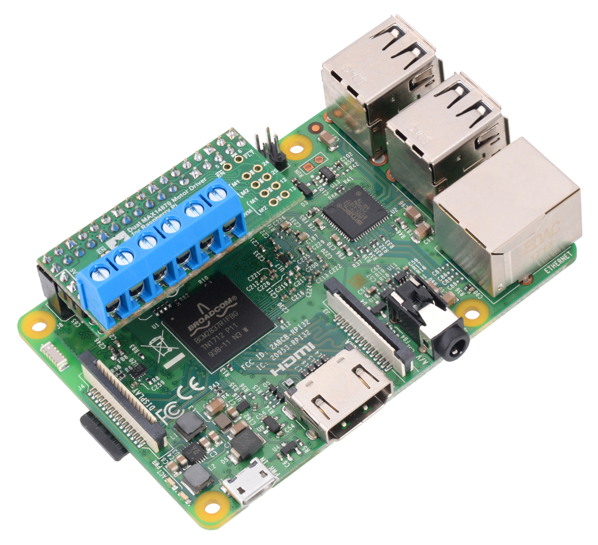
The Dual MAX14870 Motor Driver for Raspberry Pi has many of the same features as the Arduino version, but it is designed to plug into the GPIO header on a compatible Raspberry Pi (Model B+ or newer), including the Pi 3 Model B and Model A+. We provide an open-source Python library to make it easy to interface with the board. This board also has a location to connect a step-down 5 V regulator to power the Raspberry Pi from your motor’s power supply.
|
|

I am really excited about these boards because the Raspberry Pi expansion board is the first PCB I ever designed, and the Arduino shield was designed by my friend David S. Both of us are engineering students at the University of Nevada, Las Vegas who work at Pololu to complement our studies. It has been a great experience for us to learn how to design these products from the development engineers here at Pololu. Plus, getting to share these products for the first time with you is a fun way to celebrate my birthday!
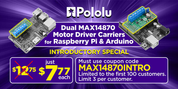
As usual for our new product releases this year, we’re offering an extra introductory discount: the first 100 customers to use coupon code MAX14870INTRO can get any mix of up to 3 of these boards for $7.77 each. (Click to add the coupon code to your cart .) Note that this introductory offer applies only to the units without connectors soldered in.
Related products


Home | Forum | Blog | Support | Ordering Information | Lists | Distributors | BIG Order Form | About | Contact
© 2001–2026 Pololu Corporation


