Voltage Regulators and Power Supplies » Step-Down (Buck) Voltage Regulators » D24V10Fx Step-Down Voltage Regulators »
Pololu 5V, 1A Step-Down Voltage Regulator D24V10F5

| Output voltage | Typical max output current1 | Input voltage range2 |
|---|---|---|
| 5 V | 1 A | 5.1 V – 36 V |
Note 1: Actual achievable continuous output current is a function of input voltage and is limited by thermal dissipation.
Note 2: Minimum input voltage is subject to dropout voltage considerations; see the dropout voltage section of product pages for more information.
Alternatives available with variations in these parameter(s): output voltage Select variant…
 Compare all products in D24V10Fx Step-Down Voltage Regulators.
| Description | Specs (10) | Pictures (9) | Resources (5) | FAQs (0) | On the blog (3) | Distributors (64) |
|---|
Overview
 |
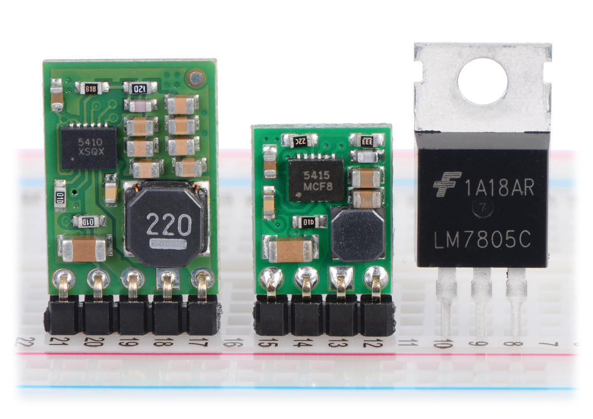 |
Pololu step-down voltage regulators D24V10Fx and D24V5Fx next to a 7805 voltage regulator in TO-220 package. |
|---|
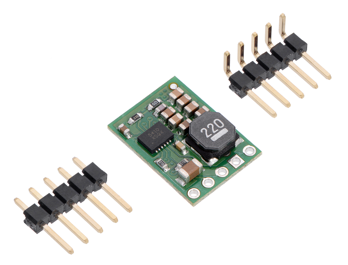
The D24V10Fx family of step-down voltage regulators features the Intersil ISL85410 1A synchronous buck regulator and generates lower output voltages from input voltages as high as 36 V. They are switching regulators (also called switched-mode power supplies (SMPS) or DC-to-DC converters) with typical efficiencies between 80% and 95%, which is much more efficient than linear voltage regulators, especially when the difference between the input and output voltage is large. These regulators have a power-save mode that activates at light loads and a low quiescent (no load) current draw, which make them well suited for applications that are run from a battery. These regulators are available in five different fixed output voltages:
Alternatives available with variations in these parameter(s): output voltage Select variant…
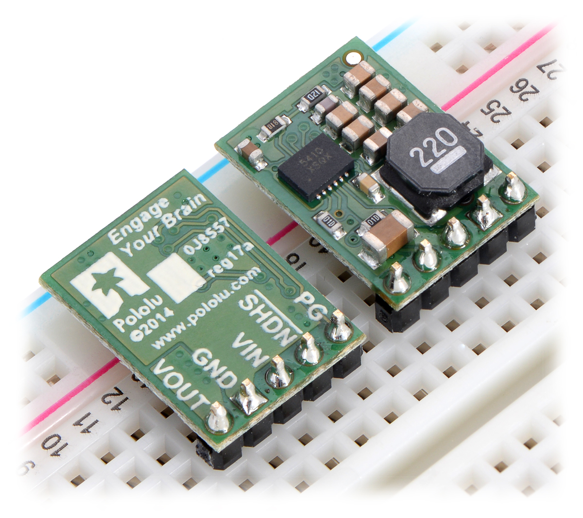
The different versions of this regulator all look very similar, so the bottom silkscreen includes a blank space where you can add your own distinguishing marks or labels. This product page applies to all five versions of the D24V10Fx family.
The SHDN pin can be used to put the board in a low-power state that reduces the quiescent current to approximately 10 µA to 20 µA per volt on VIN, and a PG (power good) output can be used to monitor the state of the regulator’s output voltage.
The regulators feature short-circuit/over-current protection, and thermal shutdown helps prevent damage from overheating. The boards do not have reverse-voltage protection.
If you do not need quite as much current, consider the very similar D24V5Fx family of step-down voltage regulators, which can deliver up to 500 mA in a wide range of output voltages:
Alternatives available with variations in these parameter(s): output voltage Select variant…
The picture on the right shows a 1 A D24V10Fx regulator next to a 0.5 A D24V5Fx regulator and a common 7805 linear regulator in a TO-220 package.
Features
- Input voltage: [output voltage + dropout voltage] to 36 V (see below for more information on dropout voltage)
- Fixed 3.3 V, 5 V, 6 V, 9 V, or 12 V output (depending on regulator version) with 4% accuracy
- Maximum output current: 1 A
- Typical efficiency of 80% to 93%
- 500 kHz switching frequency (when not in power-save mode)
- 2 ms soft-start reduces in-rush current on power-up
- 200 μA typical no-load quiescent current
- Over-current and short-circuit protection, over-temperature shutoff
- Power-good indicator can be used to tell when the regulator has reached and is maintaining its target output voltage
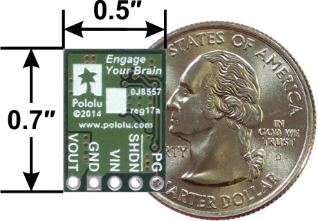
- Small size: 0.7″ × 0.5″ × 0.14″ (18 mm × 13 mm × 3.5 mm)
 |
 |
Using the regulator
Connections
The buck regulator has five connections: power good (PG). shutdown (SHDN), input voltage (VIN), ground (GND), and output voltage (VOUT).
The “power good” indicator, PG, is an open-drain output that drives low when the regulator’s output voltage falls below 80% or rises above 120% of its target output voltage. This output is also actively held low for the duration of the regulator’s 2 ms soft-start period and while the regulator is being disabled by the SHDN input or by over-temperature or over-current fault conditions. An external pull-up resistor is generally required to use this pin.
The SHDN pin can be driven low (under 0.4 V) to turn off the output and put the board into a low-power state. There is a 100 kΩ pull-up resistor between the SHDN pin and VIN, so if you want to leave the board permanently enabled, the SHDN pin can be left disconnected. While the SHDN pin is being driven low, the current draw of the regulator is dominated by the current through the pull-up resistor and will be proportional to the input voltage. (At 36 V in it will draw about 360 μA.)
The input voltage, VIN, powers the regulator. Voltages between 3 V and 36 V can be applied to VIN, but the effective lower limit of VIN is VOUT plus the regulator’s dropout voltage, which varies approximately linearly with the load (see below for graphs of dropout voltages as a function of the load). Additionally, please be wary of destructive LC spikes (see below for more information).
The output voltage, VOUT, is fixed and depends on the regulator version: the D24V10F3 version outputs 3.3 V, the D24V10F5 version outputs 5 V, the D24V10F6 version outputs 6 V, the D24V10F9 version outputs 9 V, and the D24V10F12 version outputs 12 V.
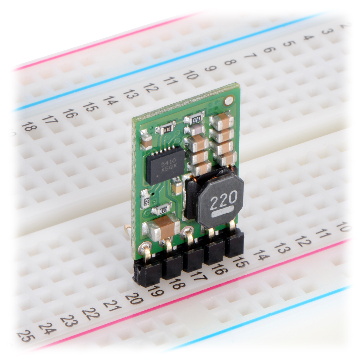
The five connections are labeled on the back side of the PCB and are arranged with a 0.1″ spacing along the edge of the board for compatibility with solderless breadboards, connectors, and other prototyping arrangements that use a 0.1″ grid. You can solder wires directly to the board or solder in either the 5×1 straight male header strip or the 5×1 right-angle male header strip that is included.
 |
Typical efficiency and output current
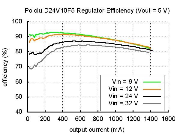
The efficiency of a voltage regulator, defined as (Power out)/(Power in), is an important measure of its performance, especially when battery life or heat are concerns. This family of switching regulators typically has an efficiency of 80% to 93%, though the actual efficiency in a given system depends on input voltage, output voltage, and output current. See the efficiency graph near the bottom of this page for more information.
In order to achieve a high efficiency at low loads, this regulator automatically goes into a power-save mode where the switching frequency is reduced. In power-save mode, the switching frequency of the regulator changes as necessary to minimize power loss. This could make it harder to filter out noise on the output caused by switching.
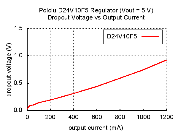
Typical dropout voltage
The dropout voltage of a step-down regulator is the minimum amount by which the input voltage must exceed the regulator’s target output voltage in order to ensure the target output can be achieved. For example, if a 5 V regulator has a 1 V dropout voltage, the input must be at least 6 V to ensure the output is the full 5 V. Generally speaking, the dropout voltage increases as the output current increases. See the “Details” section below for more information on the dropout voltage for this specific regulator version.
Details for item #2831
The graphs below show the typical efficiency and dropout voltage of the 5 V D24V10F5 regulator as a function of the output current:
 |
 |
During normal operation, this product can get hot enough to burn you. Take care when handling this product or other components connected to it.
Schematic diagram
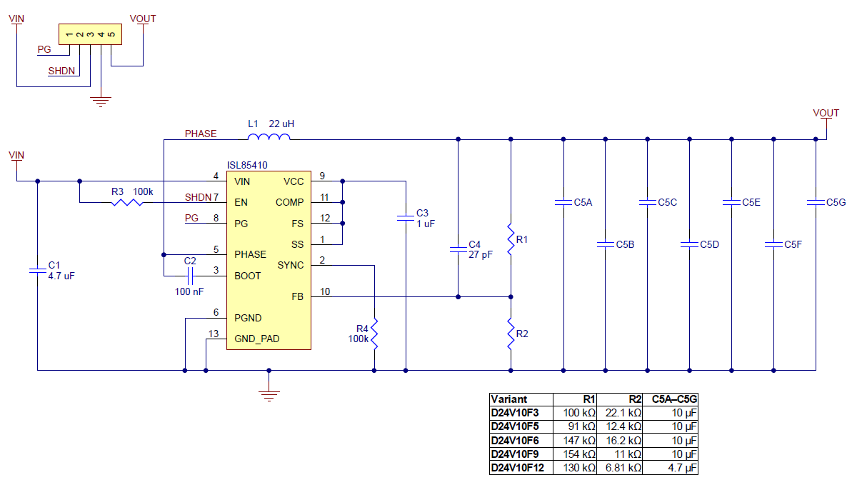 |
Schematic diagram for the Pololu D24V10Fx family of 1 A step-down voltage regulators. |
|---|
This schematic is also available as a downloadable pdf (136k pdf).
LC voltage spikes
When connecting voltage to electronic circuits, the initial rush of current can cause voltage spikes that are much higher than the input voltage. If these spikes exceed the regulator’s maximum voltage (36 V), the regulator can be destroyed. In our tests with typical power leads (~30″ test clips), input voltages above 20 V caused spikes over 36 V.
If you are connecting more than 20 V or your power leads or supply has high inductance, we recommend soldering a 33 μF or larger electrolytic capacitor close to the regulator between VIN and GND. The capacitor should be rated for at least 50 V.
More information about LC spikes can be found in our application note, Understanding Destructive LC Voltage Spikes.
Related products


Home | Forum | Blog | Support | Ordering Information | Lists | Distributors | BIG Order Form | About | Contact
© 2001–2026 Pololu Corporation
