Pololu Blog »
Posts tagged “new products”
You are currently viewing a selection of posts from the Pololu Blog. You can also view all the posts.
Popular tags: community projects new products raspberry pi arduino more…
New products: Motoron M3T453 Triple I²C Motor Controllers
|
|


We’re pleased to announce the release of our new Motoron M3T453 triple motor controllers. These compact boards make it easy to independently control up to three DC motors through an I²C interface; they support motor supply voltages from 4.5 V to 44 V and can supply up to 0.8 A per channel.
Four M3T453 versions are available to provide different connector options:
M3T453 with JST SH-style connectors: |
M3T453 with 0.1″-pitch through-holes: |
||
|
|


Since you can connect multiple Motoron controllers to the same I²C bus, these little modules are hard to beat for applications where you need to drive lots of small motors. In particular, the versions with JST SH-style connectors allow you to make all your motor connections modular and detachable when combined with our 2-pin JST SH-style cables and JST SH-Style Connector Board for Micro Metal Gearmotors.
Introductory special discount! Use coupon code M3T453INTRO to get any version for $14.95 each.
Related products


New encoders with connectors for 20D mm metal gearmotors
We are excited to introduce encoders with JST PH-type connectors for our 20D mm metal gearmotors, available in two versions to better satisfy different application constraints:
- Magnetic Encoder Pair Kit with Top-Entry Connector for 20D mm Metal Gearmotors, 12 CPR, 2.7-18V
- Magnetic Encoder Pair Kit with Side-Entry Connector for 20D mm Metal Gearmotors, 12 CPR, 2.7-18V
|
|
||||
|
|


The top-entry connector allows the cable to come straight out the back, keeping things compactly in-line with the motor, while the side-entry connector is good for applications where there isn’t much space past the rear of the motor. We are also continuing to offer our original encoder board with through-holes, which allows wires to be soldered to the board for especially compact installations.
With these new encoders, you just have to solder the board to the two motor tabs, put the magnetic disc on the backshaft, and plug in your cable! And our just-released JST PH cables give you plenty of options to choose from:
|
|


| JST PH-Style 6-Pin Cables | |||||
|---|---|---|---|---|---|
| Pins | Terminations | Length | Item # | Price | |
 |
6 | double-sided (JST PH to JST PH) |
10 cm (4″) | #5643 | $3.23 |
| 16 cm (6.3″) | #5644 | $3.56 | |||
| 25 cm (10″) | #5645 | $4.04 | |||
| 40 cm (16″) | #5646 | $4.85 | |||
| 63 cm (25″) | #5647 | $6.08 | |||
| single-sided (JST PH to 0.1″ crimp pins) |
12 cm (4.5″) | #5640 | $3.34 | ||
| 30 cm (12″) | #5641 | $4.31 | |||
| 75 cm (30″) | #5642 | $6.73 | |||
The double-sided cables can be used with our new JST PH-style connector breakout boards, which are also available in top-entry and side-entry versions.
|
|


Introductory special discount! Use coupon code 20DENCINTRO to get some of these new encoders for just $6.95 per pair.
Related products


New products: D24V7Fx 36V, 600mA low-cost step-down voltage regulators
|
|
|


We just released our D24V7Fx step-down voltage regulator family of basic buck regulators, which generate lower voltages from input voltages as high as 36 V while supporting maximum continuous output currents of 600 mA across all combinations of input and output voltages. Because they are switching regulators, they are much more efficient than linear voltage regulators, especially when the difference between the input and output voltage is large. This family includes six versions with fixed output voltages ranging from 3.3 V to 12 V:
| Regulator | Output voltage | Max continuous output current |
Input voltage range1 | Size | Special features | Price |
|---|---|---|---|---|---|---|
| #5592: D24V7F3 | 3.3 V | 600 mA | 4 V – 36 V | 0.34″ × 0.54″ | Short-circuit protection, thermal shutdown |
$2.75 |
| #5593: D24V7F5 | 5 V | 5.1 V – 36 V | ||||
| #5594: D24V7F6 | 6 V | 6.1 V – 36 V | ||||
| #5595: D24V7F7 | 7.5 V | 7.6 V – 36 V | ||||
| #5596: D24V7F9 | 9 V | 9.2 V – 36 V | ||||
| #5597: D24V7F12 | 12 V | 12.2 V – 36 V | ||||
| Note 1: Minimum input voltage is subject to dropout voltage considerations; see the dropout voltage section of product pages for more information. | ||||||
We manufacture these boards in-house at our Las Vegas facility, so if one of the stock voltages doesn’t fit your needs, we can customize these regulators to output other voltages. If you are interested in customization, please contact us for a quote.
 |
The main distinguishing feature of this regulator is its small size and low cost. At just $2.75 in single-unit quantities, it is our lowest-price regulator yet! We were able to achieve this by having one of our high school summer interns do the board design:
 |
High-school summer intern routing the D24V7Fx regulator PCB, July 2025. |
|---|
I’m kidding about that making the price lower, of course. Our engineers still went over everything, and unlike some competing products you might encounter, we provide detailed performance data such as the quiescent current characteristics:
 |
Also, each production unit is fully automatically optically inspected and tested. We have been putting a lot of effort into automating our testing and packaging, and that is the real key to being able to offer these low prices. More behind-the-scenes information on the robots making our products coming soon!
Introductory special discount! Use coupon code D24V7FXINTRO to try out these new regulators for just $2.22 each.
Related products


New product: A89301-Based Sensorless Brushless Motor Controller, 50V, 11A
 |
 |
Yes, you read that right: brushless! We’re excited to finally announce our A89301-Based Sensorless Brushless Motor Controller, 50V, 11A, our first board designed to control a brushless DC motor.
Pololu has never offered any BLDC motor drivers or controllers until now (we’ve had stepper motor drivers for a long time, but that’s typically not what people mean when they ask for a brushless motor driver), and I think it’s easier to appreciate some of our reasons for this if you look into their principles of operation.
A brushed DC motor can easily be driven with a simple direct current produced from a constant voltage, and its speed can be controlled by varying that voltage proportionally (or by using PWM, which effectively produces a lower average voltage). This is because it has a commutator and some contacts, or “brushes”, that switch the direction of the current in the windings as they rotate inside a fixed magnetic field, and that maintains a steady torque on the motor shaft to keep it spinning. Consequently, the simplest brushed DC motor drivers are not much more than amplifiers that turn low-voltage, low-current control signals into higher power outputs capable of driving a motor.
By contrast, the construction of a brushless DC motor is relatively simple. The coils are located on the fixed part of the motor (stator) and are directly connected to the motor’s terminals, and the magnets are on the rotating part (rotor) instead. Eliminating the brushes and commutator accounts for some of the advantages of brushless motors, including higher efficiency (partly due to less friction) and longer lifetimes (fewer parts to wear out) compared to brushed motors. The trade-off for this reduced mechanical complexity is increased control complexity: something else now has to switch the coil currents appropriately to maintain a steady torque on the rotor, and that is the responsibility of the brushless motor driver.
 |
A pair of disassembled DC motors. Brushed motor (left): end cap with brushes, rotor with coils and commutator, case with fixed magnets. Brushless outrunner motor (right): rotor with magnets and case, stator with coils. |
|---|
In order to produce torque, a motor’s windings must generate magnetic forces tangential to the axis of rotation. (I saw an analogy that compares this to using a wrench: you can torque a bolt by applying a tangential force to the wrench handle, but pushing or pulling on the wrench parallel to the handle doesn’t do anything useful.) Since a brushless motor’s magnets rotate, the fixed coils’ magnetic fields must also rotate to keep acting on the rotor tangentially, and this means the coils need to be energized in a rotating sequence.
The simplest way to do this is with an open-loop technique that simply drives the brushless motor using a sequence with fixed timing. However, for better reliability and efficiency, it is helpful to know the actual position of the rotor so that the timing of the sequence can be adjusted accordingly. There are two approaches to doing this, each with their own upsides and downsides: sensored control relies on a position sensor in the motor (like an encoder) to directly measure its position, while sensorless control uses the back-EMF (electromotive force) induced on the coils by the motor’s rotation to calculate its position.
I hope this brief overview conveys some of the additional considerations that are involved in making a brushless DC motor control system. This complexity, and the wide range of electronic parts released by various manufacturers to address it, means that it’s been hard for us to decide on a direction to take when it came to trying to design our own brushless driver or controller. Another factor was that we don’t sell any brushless motors (yet), which made it kind of a chicken-and-egg problem: does it make sense for us to develop a brushless driver when we have no brushless motors, and does it make sense for us to source brushless motors to sell when we have nothing to drive them?
 |
Of course, to resolve that dilemma, you have to start with one or the other, and Allegro offering development support for their A89301 brushless DC gate driver IC made it an easy decision for us to move forward with a board for it. Our A89301-Based Sensorless Brushless Motor Controller, 50V, 11A combines the A89301 with external MOSFETs to enable sensorless control of 3-phase BLDC motors at voltages from 5.5 V to 48 V and with phase currents up to 11 A. The A89301 uses a fully-integrated field-oriented control (FOC) algorithm that computes the exact position of the rotor so that the coil currents can be controlled accordingly, optimizing torque and efficiency. It accepts speed inputs via analog voltage, PWM duty cycle, pulse frequency, or I²C signals to simplify the process of getting a brushless motor running without having to write your own complex low-level motor control code. We offer versions with soldered header pins and terminal blocks or without through-hole connectors.
Introductory special discount! Use coupon code A89301INTRO to get either version for $19.95 each.
To make use of all of the A89301 IC’s features and settings, including lock (stall) detection and multiple motor startup options, it needs to be configured through I²C. Our board’s 4-pin I²C connector (Qwiic and STEMMA QT compatible) makes it easy to connect it to one of our USB-to-I²C Adapters and use the Pololu A89301 Configuration Utility software for Windows (based on Allegro’s own evaluation board software) to interface with the A89301.
 |
The Pololu A89301 Configuration Utility software. |
|---|
 |
An A89301-Based Sensorless Brushless Motor Controller connected to a computer with a Pololu Isolated USB-to-I²C Adapter (IOREF shorted to 2V8). |
|---|
This is our first brushless motor control solution, and we definitely don’t intend it to be our last. While we have plans for other products, we’re also interested in hearing from you: What are you looking for in a BLDC motor system? What kinds of brushless motors, drivers, and controllers would you like to see us offer?
Related products


New products: JST SH-style connector boards
|
|
|


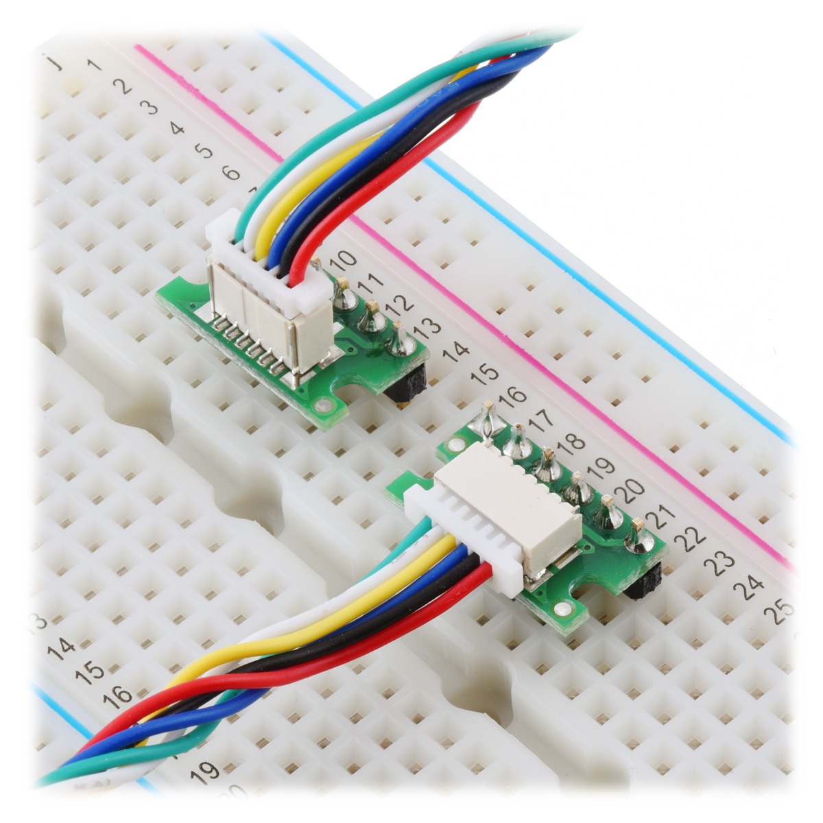
We have released a series of breakout boards for our new JST SH-type cables that serve as adapters between these cables and breadboard-compatible 0.1″ through-holes. The new boards are available in pin counts from 2 through 5 and in top-entry and side-entry variations. We also have existing 6-pin versions that we originally released as accessories for our micro metal gearmotor encoders, so the through-holes are labeled on the silkscreen according to the pins they would map to on our encoders, but these can also be used as general-purpose breakout boards for our 6-pin cables. Here’s the full selection:
| Top entry | Side entry |
|---|---|
| 2-pin | |
 |
 |
| 3-pin | |
 |
 |
| 4-pin | |
 |
 |
| 5-pin | |
 |
 |
| 6-pin | |
 |
 |
New products: 40 new JST SH-style cables
You may have noticed several of our newer boards have JST SH-style connectors on them, from 2 pins on these micro metal gearmotor connector boards to 3 pins on these digital distance sensors to 4 pins on these contactless current sensor carriers and several I2C products including our USB-to-I2C adapters. We now have a series of compatible JST SH-style female cables to go with them. We are stocking them in a variety of lengths, pin counts, and termination styles, making 40 new cables in all to choose from!
| Pins | Terminations | Length | Item # | |
|---|---|---|---|---|
 |
1×2 | double-sided (female-female) |
10 cm (4″) | #5503 |
| 16 cm (6.3″) | #5504 | |||
| 25 cm (10″) | #5505 | |||
| 40 cm (16″) | #5506 | |||
| 63 cm (25″) | #5507 | |||
| single-sided (female- unterminated) |
12 cm (4.5″) | #5500 | ||
| 30 cm (12″) | #5501 | |||
| 75 cm (30″) | #5502 |
| Pins | Terminations | Length | Item # | |
|---|---|---|---|---|
 |
1×3 | double-sided (female-female) |
10 cm (4″) | #5513 |
| 16 cm (6.3″) | #5514 | |||
| 25 cm (10″) | #5515 | |||
| 40 cm (16″) | #5516 | |||
| 63 cm (25″) | #5517 | |||
| single-sided (female- unterminated) |
12 cm (4.5″) | #5510 | ||
| 30 cm (12″) | #5511 | |||
| 75 cm (30″) | #5512 |
| Pins | Terminations | Length | Item # | |
|---|---|---|---|---|
 |
1×4 | double-sided (female-female) |
10 cm (4″) | #5523 |
| 16 cm (6.3″) | #5524 | |||
| 25 cm (10″) | #5525 | |||
| 40 cm (16″) | #5526 | |||
| 63 cm (25″) | #5527 | |||
| single-sided (female- unterminated) |
12 cm (4.5″) | #5520 | ||
| 30 cm (12″) | #5521 | |||
| 75 cm (30″) | #5522 |
| Pins | Terminations | Length | Item # | |
|---|---|---|---|---|
 |
1×5 | double-sided (female-female) |
10 cm (4″) | #5533 |
| 16 cm (6.3″) | #5534 | |||
| 25 cm (10″) | #5535 | |||
| 40 cm (16″) | #5536 | |||
| 63 cm (25″) | #5537 | |||
| single-sided (female- unterminated) |
12 cm (4.5″) | #5530 | ||
| 30 cm (12″) | #5531 | |||
| 75 cm (30″) | #5532 |
| Pins | Terminations | Length | Item # | |
|---|---|---|---|---|
 |
1×6 | double-sided (female-female) |
10 cm (4″) | #5543 |
| 16 cm (6.3″) | #5544 | |||
| 25 cm (10″) | #5545 | |||
| 40 cm (16″) | #5546 | |||
| 63 cm (25″) | #5547 | |||
| single-sided (female- unterminated) |
12 cm (4.5″) | #5540 | ||
| 30 cm (12″) | #5541 | |||
| 75 cm (30″) | #5542 |
The JST SH-style connector has a 1 mm pitch, making it a good choice for small modules, and the wires are 28 AWG. The double-sided cables have twisted wires and female connectors on both ends, while the single-sided versions have a connector on one end and unterminated wires on the other. The single-ended versions can easily be cut to shorter if desired, and remember that you can also cut the double-sided cables in half to get single-sided cables that are 5 cm, 8 cm, and 20 cm long.
The 4-pin versions are compatible with SparkFun’s Qwiic and Adafruit’s STEMMA QT.
We’ve had 6-pin cables for our Micro Metal Gearmotor encoders for years, but with this new line of cables, we’re offering a 6-pin version that matches the standardized color order, with black always corresponding to pin 1 and red always corresponding to pin 2. For reference, here is our selection of those original 6-pin cables, which have the green wire on pin 1:
| Pins | Terminations | Length | Item # | |
|---|---|---|---|---|
 |
1×6 | double-sided (female-female) |
10 cm (4″) | #4765 |
| 16 cm (6.3″) | #4766 | |||
| 25 cm (10″) | #4767 | |||
| 40 cm (16″) | #4768 | |||
| 63 cm (25″) | #4769 | |||
| single-sided (female- unterminated) |
12 cm (4.5″) | #4762 | ||
| 30 cm (12″) | #4763 | |||
| 75 cm (30″) | #4764 |
What new products would you like to see with connectors for these cables?
New products: Pololu Isolated Solid State Relay/Switch, SPST
 |
We’re happy to announce our new Isolated Solid State Relay/Switch boards! These modules function as solid state, single-pole, single-throw (SPST) relays or switches that can be controlled by low-current signals between 2.7 V and 40 V. The control signal activates an optically coupled driver that turns on a pair of output MOSFETs, which keeps the outputs electrically isolated from the input side. The MOSFETs are arranged back-to-back to make the outputs symmetric and bidirectional (so the board can be used as a high-side or low-side switch).
 |
These boards make good replacements for mechanical relays in many situations, since their semiconductor-based design allows them to avoid problems like contact wear and arcing that limit the service life of mechanical relays. They are also silent and generally much smaller than a typical mechanical relay with a comparable current rating. Two versions of the solid state relay/switch are available with different voltage and current capabilities:
- Pololu Isolated Solid State Relay/Switch, SPST, 30V, 11A
- Pololu Isolated Solid State Relay/Switch, SPST, 60V, 7A
 |
Three-wire and two-wire (with EN and VIN tied together) control options for the Pololu Isolated Solid State Relay/Switch, SPST (60V version shown). |
|---|
Introductory special discount! Use coupon code SSRELAYINTRO to get either version for $3.50 each.
Related products


More new current sensors!
 |
|
|
|


We have released even more current sensors! As with our assortment of other active and preferred current sensors, these new boards are based on Allegro current-sensing ICs and have analog outputs with voltage proportional to the AC or DC current passing through the sensor while offering full electrical isolation of the current path from the sensor’s electronics. This isolation allows them to be inserted anywhere in the current path, including on the high side, and because the current path resistance is on the order of 2 mΩ or less, there is minimal effect on the rest of the system. Here’s a quick summary of the new sensor families:
Allegro ACS37041/ACS37042
These low-cost bidirectional current sensors have ranges of -10 A to +10 A or -30 A to +30 A with dedicated versions for 3.3 V and 5 V systems. The sensor itself is a tiny 5-pin SOT-23 package, which allows for an extra-compact, “micro” carrier board that is approximately 1/5th the size of our next smallest current sensor carrier. We also have versions in our standard “compact” form factor, which for these sensors end up being the larger of the two form factors available. These larger versions can accommodate a wider variety of connectors and thicker wires, and they have the same overall dimensions and current-path mounting hole arrangements as our other “compact” current sensor carriers.
|
|
||
|
|


The ACS37041 and ACS37042 are almost identical, with the key difference being that the ACS37042 has a higher isolation voltage rating. To support operation at higher voltages, the carrier boards for the ACS37042 versions have routed slots for higher creepage distances along the PCB surface. The pictures above show the ACS37041 carriers on the left and the ACS37042 carriers on the right.
The following table shows all of our ACS37041 and ACS37042 carrier options:
| Pololu Item # |
Part Suffix | Isolation Rating 1 |
Supply Voltage | Current Range |
Sensitivity (mV/A) |
Zero Point | Size | PCB Details |
Min PCB Creepage 2 |
Price | |
|---|---|---|---|---|---|---|---|---|---|---|---|
| ACS3704x Micro Carriers | |||||||||||
 ACS37041 |
#5440 (coming June 2025) | 010B3 | 100 VRMS | 3.0 V to 3.6 V | ±10 A | 132 | 1.65 V | 0.3″×0.4″ 7.6×10.2 mm |
2 layers, 1-oz copper |
1.6 mm | $4.15 |
| #5441 | 030B3 | ±30 A | 44 | ||||||||
| #5442 | 010B5 | 4.5 V to 5.5 V | ±10 A | 200 | 2.5 V | ||||||
| #5443 | 030B5 | ±30 A | 66.7 | ||||||||
 ACS37042 |
#5450 | 010B3 | 285 VRMS | 3.0 V to 3.6 V | ±10 A | 132 | 1.65 V | 2.0 mm | $4.69 | ||
| #5451 | 030B3 | ±30 A | 44 | ||||||||
| #5452 (coming June 2025) | 010B5 | 4.5 V to 5.5 V | ±10 A | 200 | 2.5 V | ||||||
| #5453 (coming June 2025) | 030B5 | ±30 A | 66.7 | ||||||||
| ACS3704x Compact Carriers | |||||||||||
 ACS37041 |
#5444 (coming June 2025) | 010B3 | 100 VRMS | 3.0 V to 3.6 V | ±10 A | 132 | 1.65 V | 0.7″×0.8″ 17.8×20.3 mm |
2 layers, 2-oz copper |
1.6 mm | $4.45 |
| #5445 | 030B3 | ±30 A | 44 | ||||||||
| #5446 | 010B5 | 4.5 V to 5.5 V | ±10 A | 200 | 2.5 V | ||||||
| #5447 | 030B5 | ±30 A | 66.7 | ||||||||
 ACS37042 |
#5454 | 010B3 | 285 VRMS | 3.0 V to 3.6 V | ±10 A | 132 | 1.65 V | 3.0 mm | $4.99 | ||
| #5455 | 030B3 | ±30 A | 44 | ||||||||
| #5456 (coming June 2025) | 010B5 | 4.5 V to 5.5 V | ±10 A | 200 | 2.5 V | ||||||
| #5457 (coming June 2025) | 030B5 | ±30 A | 66.7 | ||||||||
| Note 1: IC component rating per manufacturer datasheet. | |||||||||||
| Note 2: Minimum creepage along PCB surface based on layout design only. Other creepage distances, e.g. along the body of the component, may be lower. | |||||||||||
Allegro ACS37030
These sensors measure bidirectional currents from -20 A to +20 A or -65 A to +65 A, and they are intended for 3.3 V systems. What makes them really special are their extra-low (40 ns typical) response times and extra-high 5 MHz bandwidth, which are made possible by their combined use of two sensing technologies: a Hall effect sensor captures DC and low-frequency current information and an inductive coil captures high-frequency signals. The following table shows our available options:
| Pololu Item # |
Part Suffix | Supply Voltage | Current Range |
Sensitivity (mV/A) |
Zero Point | Size | PCB Details |
Price | |
|---|---|---|---|---|---|---|---|---|---|
| ACS37030 Compact Carriers | |||||||||
 |
#5230 | 020B3 | 3.0 V to 3.6 V | ±20 A | 66 | 1.65 V | 0.7″×0.8″ 17.8×20.3 mm |
2 layers, 2-oz copper |
$8.95 |
| #5231 (coming July 2025) | 040B3 | ±40 A | 33 | ||||||
| #5232 | 065B3 | ±65 A | 20.3 | ||||||
| ACS37030 Large Carriers | |||||||||
 |
#5235 | 065B3 | 3.0 V to 3.6 V | ±65 A | 20.3 | 1.65 V | 1.4″×1.2″ 35.6×30.5 mm |
6 layers, 2-oz copper |
$11.95 |
| #5236 (coming July 2025) | 040B3 | ±40 A | 33 | ||||||
These sensors are available in our standard compact form factor, which is great for use in space-constrained systems, and the higher-current versions are also available in our standard large form factor, which supports more connection options for higher-current applications. The large carriers offer better thermal dissipation thanks to their 6-layer PCBs and increased surface area, and the holes and slots for the current path connection points accommodate thicker wires along with a variety of high-current connectors (e.g. lugs, solderless ring terminals, and 4-pin terminal blocks). Having these standard form factors available makes it easier to swap among different boards to compare different sensor ICs, and having different form factors available for the same sensor IC also makes it possible to evaluate how things like PCB area and the number of copper layers affects the sensor’s thermal performance
All our current sensors
These new additions bring us up to 96 total active and preferred current sensor carriers! Here’s a handy table comparing them all:
 |
 |
 |
 |
 |
 |
 |
 |
 |
 |
 |
 |
 |
|
|---|---|---|---|---|---|---|---|---|---|---|---|---|---|
| ACS3704x Current Sensor Micro Carriers |
ACS3704x Current Sensor Compact Carriers |
ACS711 Current Sensor Carriers |
ACS71240 Current Sensor Carriers |
ACS724 Current Sensor Carriers |
ACS37220 Current Sensor Compact Carriers |
ACS37220 Current Sensor Large Carriers |
ACS37030 Current Sensor Compact Carriers |
ACS37030 Current Sensor Large Carriers |
ACS72981 Current Sensor Compact Carriers |
ACS72981 Current Sensor Large Carriers |
CT432/CT433 TMR Current Sensor Compact Carriers |
CT432/CT433 TMR Current Sensor Large Carriers |
|
| Allegro Sensor | ACS3704x | ACS711KEXT | ACS71240 | ACS724LLCTR | ACS37220 | ACS37030 | ACS72981xLR | CT432/CT433 | |||||
| Sensing technology | Hall effect | Hall effect | Hall effect | Hall effect | Hall effect | Hall effect + inductive coil | Hall effect | XtremeSense™ TMR (tunneling magnetoresistance) |
|||||
| Logic voltage range | 3.3V versions: 3.0–3.6 V 5V versions: 4.75–5.5 V |
3.0–5.5 V | 3.3V ver: 3.0–3.6 V 5V ver: 4.5–5.5 V |
4.5–5.5 V | 3.3V versions: 3.15–3.45 V 5V versions: 4.5–5.5 V |
3.0–3.6 V | 3.3V versions: 3.0–3.6 V 5V versions: 4.5–5.5 V |
3.3V versions: 3.0–3.6 V 5V versions: 4.75–5.5 V |
|||||
| Family current range | 10–30 A | 15.5–31 A | 10–50 A | 2.5–50 A | 100–200 A | 20–65 A | 50–200 A | 20–70 A | |||||
| Current range/ sensitivity of individual versions |
ACS37041: 3.3V Bidirectional: ±30 A / 44 mV/A 5V Bidirectional: ±10 A / 200 mV/A ±30 A / 66.7 mV/A ACS37042: 3.3V Bidirectional: ±10 A / 132 mV/A ±30 A / 44 mV/A |
ACS37041: 3.3V Bidirectional: ±30 A / 44 mV/A 5V Bidirectional: ±10 A / 200 mV/A ±30 A / 66.7 mV/A ACS37042: 3.3V Bidirectional: ±10 A / 132 mV/A ±30 A / 44 mV/A |
Bidirectional:(1) ±15.5 A / 90 mV/A ±31 A / 45 mV/A |
3.3V Bidirectional: ±10 A / 132 mV/A ±30 A / 44 mV/A ±50 A / 26.4 mV/A 5V Bidirectional: ±10 A / 200 mV/A ±30 A / 66 mV/A ±50 A / 40 mV/A 5V Unidirectional: 0–50 A / 80 mv/A |
5V Bidirectional:(2) ±2.5 A / 800 mV/A ±5 A / 400 mV/A ±10 A / 200 mV/A ±20 A / 100 mV/A ±30 A / 66 mV/A ±50 A / 40 mV/A 5V Unidirectional:(2) 0–5 A / 800 mv/A 0–10 A / 400 mv/A 0–20 A / 200 mv/A 0–30 A / 133 mV/A |
3.3V Bidirectional: ±100 A / 13.2 mV/A ±150 A / 8.8 mV/A 5V Bidirectional: ±100 A / 20 mV/A ±150 A / 13.3 mV/A ±200 A / 10 mV/A |
3.3V Bidirectional: ±100 A / 13.2 mV/A ±150 A / 8.8 mV/A 5V Bidirectional: ±100 A / 20 mV/A ±150 A / 13.3 mV/A ±200 A / 10 mV/A |
3.3V Bidirectional: ±20 A / 66 mV/A ±65 A / 20.3 mV/A |
3.3V Bidirectional: ±65 A / 20.3 mV/A |
3.3V Bidirectional:(1) ±50 A / 26.4 mV/A ±100 A / 13.2 mV/A ±150 A / 8.8 mV/A ±200 A / 6.6 mV/A 3.3V Unidirectional:(1) 0–50 A / 52.8 mv/A 0–100 A / 26.4 mv/A 0–150 A / 17.6 mv/A 0–200 A / 13.2 mv/A 5V Bidirectional:(2) ±50 A / 40 mV/A ±100 A / 20 mV/A ±150 A / 13.3 mV/A ±200 A / 10 mV/A 5V Unidirectional:(2) 0–50 A / 80 mv/A 0–100 A / 40 mv/A 0–150 A / 26.7 mv/A |
3.3V Bidirectional:(1) ±50 A / 26.4 mV/A ±100 A / 13.2 mV/A ±150 A / 8.8 mV/A ±200 A / 6.6 mV/A 3.3V Unidirectional:(1) 0–50 A / 52.8 mv/A 0–100 A / 26.4 mv/A 0–150 A / 17.6 mv/A 0–200 A / 13.2 mv/A 5V Bidirectional:(2) ±50 A / 40 mV/A ±100 A / 20 mV/A ±150 A / 13.3 mV/A ±200 A / 10 mV/A 5V Unidirectional:(2) 0–50 A / 80 mv/A 0–100 A / 40 mv/A 0–150 A / 26.7 mv/A |
3.3V Bidirectional: ±20 A / 50 mV/A ±30 A / 33.3 mV/A ±50 A / 20 mV/A ±70 A / 14.3 mV/A 3.3V Unidirectional: 0–20 A / 100 mv/A 0–30 A / 66.7 mv/A 0–50 A / 40 mv/A 0–65 A / 30.8 mv/A 5V Bidirectional: ±20 A / 100 mV/A ±30 A / 66.7 mV/A ±50 A / 40 mV/A ±65 A / 30.8 mV/A 5V Unidirectional: 0–20 A / 200 mv/A 0–30 A / 133.3 mv/A 0–50 A / 80 mv/A 0–70 A / 57.1 mv/A |
3.3V Bidirectional: ±50 A / 20 mV/A ±70 A / 14.3 mV/A 3.3V Unidirectional: 0–50 A / 40 mv/A 0–65 A / 30.8 mv/A 5V Bidirectional: ±50 A / 40 mV/A ±65 A / 30.8 mV/A 5V Unidirectional: 0–50 A / 80 mv/A 0–70 A / 57.1 mv/A |
| IC current path resistance | 1.6 mΩ | 0.6 mΩ | 0.6 mΩ | 0.6 mΩ | 0.1 mΩ | 0.7 mΩ | 0.2 mΩ | 1 mΩ | |||||
| PCB | 2 layers, 1-oz copper |
2 layers, 2-oz copper |
2 layers, 2-oz copper |
2 layers, 2-oz copper |
2 layers, 2- or 4-oz copper(4) |
2 layers, 2-oz copper |
6 layers, 2-oz copper |
2 layers, 2-oz copper |
6 layers, 2-oz copper |
6 layers, 2-oz copper |
6 layers, 2-oz copper |
2 or 4 layers(5), 2-oz copper |
6 layers, 2-oz copper |
| Max bandwidth | 150 kHz | 100 kHz | 120 kHz | 120 kHz(3) | 150 kHz | 5 MHz | 250 kHz | 1 MHz | |||||
| Size | 0.3″ × 0.4″ | 0.7″ × 0.8″ | 0.7″ × 0.8″ | 0.7″ × 0.8″ | 0.7″ × 0.8″ | 0.7″ × 0.8″ | 1.4″ × 1.2″ | 0.7″ × 0.8″ | 1.4″ × 1.2″ | 0.7″ × 0.8″ | 1.4″ × 1.2″ | 0.8″ × 1.1″ | 1.4″ × 1.2″ |
| Overcurrent fault output |
User-configurable threshold | ||||||||||||
| Common-mode field rejection | |||||||||||||
| Nonratiometric output | |||||||||||||
| 1-piece price | $4.15 | $4.45 | $4.85 | $5.25 | $9.95 – $11.49 | $6.95 | $10.95 | $8.95 | $11.95 | $13.95 | $16.95 | $12.95 | $16.95 |
Note 1: Sensitivity when Vcc = 3.3 V; actual sensitivity is ratiometric (i.e. it is proportional to Vcc).
Note 2: Sensitivity when Vcc = 5 V; actual sensitivity is ratiometric (i.e. it is proportional to Vcc).
Note 3: Bandwidth can be reduced by adding a filter capacitor.
Note 4: 50A version uses 4-oz copper PCB; all other versions use 2-oz copper.
Note 5: 50A and higher versions use a 4-layer PCB; all other versions use a 2-layer PCB.
You can also use the following selection box to see all these options sorted by current range:
Alternatives available with variations in these parameter(s): current range Select variant…
Related products


New products: Isolated USB-to-I²C Adapters
 |
We’re excited to introduce our new isolated USB-to-I²C adapters! These boards make it easy to control your I²C device from your PC or other USB host, giving your applications access to a world of sensors and actuators or simplifying evaluation and troubleshooting of I²C hardware. Two versions are available, one that requires VCC to be supplied separately to the I²C side and one that can deliver 5V or 3.3V power to your I²C bus from your USB port while still maintaining electrical isolation.
|
|


Both adapters offer full galvanic isolation to protect your PC from your experimental circuits and to avoid subtle common-ground problems.
 |
Schematic diagram of the Pololu Isolated USB-to-I²C Adapter with Isolated Power. |
|---|
The firmware is open source, so you can customize them, and the galvanic isolation building blocks used in these adapters are available separately in smaller modules if you want to implement your own isolated systems.
Related products


Finding common ground is for suckers!
|
|


We usually think of ground as a common point in our circuits, and many problems arise from not having a good (or any) ground connection. But there’s also the flip side of unexpected ground connections leading to malfunction or even destruction of our electronics systems. Keeping grounds separated can be an important part of improving functionality and reliability when connecting many parts or boards together, which is why we have continued our push into simplifying electrical isolation with the release of four new I²C isolator boards:
- Pololu I²C Isolator, ISO1640
- Pololu I²C Isolator with Connectors, ISO1640
- Pololu I²C Isolator with Isolated Power, ISO1640, MIE1W0505BGLVH, 5V/3.3V, 200mA
- Pololu I²C Isolator with Isolated Power and Connectors, ISO1640, MIE1W0505BGLVH, 5V/3.3V, 200mA
These modules enable bidirectional I²C communication between devices while maintaining complete galvanic isolation between the two sides. This prevents the unexpected flow of current between the two sides, and it can also prevent destructive voltages on one side from propagating into the other (note that in this scenario one side will still be destroyed, but at least the damage will be contained to the isolated portion). The modules are based on Texas Instruments’ ISO1640B, which supports bidirectional data transfer up to 1.7 MHz. The clock line (SCL) is also bidirectional, which allows for clock stretching.
|
|


Two board versions are available, one with isolated power and one without. The version with isolated power can deliver regulated, isolated power at 3.3 V or 5 V to the target thanks to the incorporation of the MPS MIE1W0505BGLVH (which you might recognize from the standalone power module we released a few months ago), while the simpler version without isolated power requires the two sides to be powered separately.
 |
Schematic diagram of the Pololu I²C Isolator with Isolated Power. |
|---|
Each version is optionally available with JST SH-style 4-pin connectors that are compatible with Qwiic and Stemma QT.
|
|


Introductory special discounts! Use coupon code I2CISOINTRO to get the versions without isolated power for $3.49 and use coupon code P5392P5393INTRO to get the versions with isolated power for $6.49.
Related products


Home | Forum | Blog | Support | Ordering Information | Lists | Distributors | BIG Order Form | About | Contact
© 2001–2026 Pololu Corporation


