Pololu Blog »
Pololu Blog (Page 16)
Welcome to the Pololu Blog, where we provide updates about what we and our customers are doing and thinking about. This blog used to be Pololu president Jan Malášek’s Engage Your Brain blog; you can view just those posts here.
Popular tags: community projects new products raspberry pi arduino more…
New product: Case with Fan for RoboClaw 2x15, 2x30, and 2x45
|
|
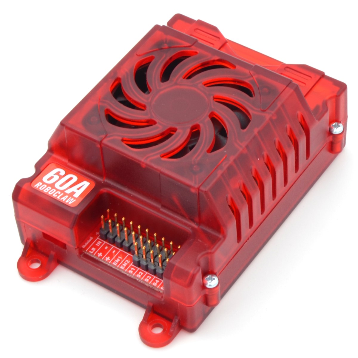
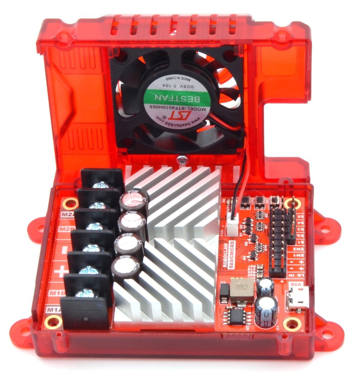
With this new RoboClaw case, our selection of RoboClaw products just got even cooler – literally! In addition to protecting the motor controller, this case also has an integrated fan, which will allow an enclosed RoboClaw to deliver higher continuous currents and sustain peak currents longer. The case works with 2x15A, 2x30A, 2x45A, and ST 2x45A RoboClaw motor controllers and features cutouts for accessing the motor outputs and the various control input header pins.
Related products


Updated product: A-Star 32U4 Prime LV
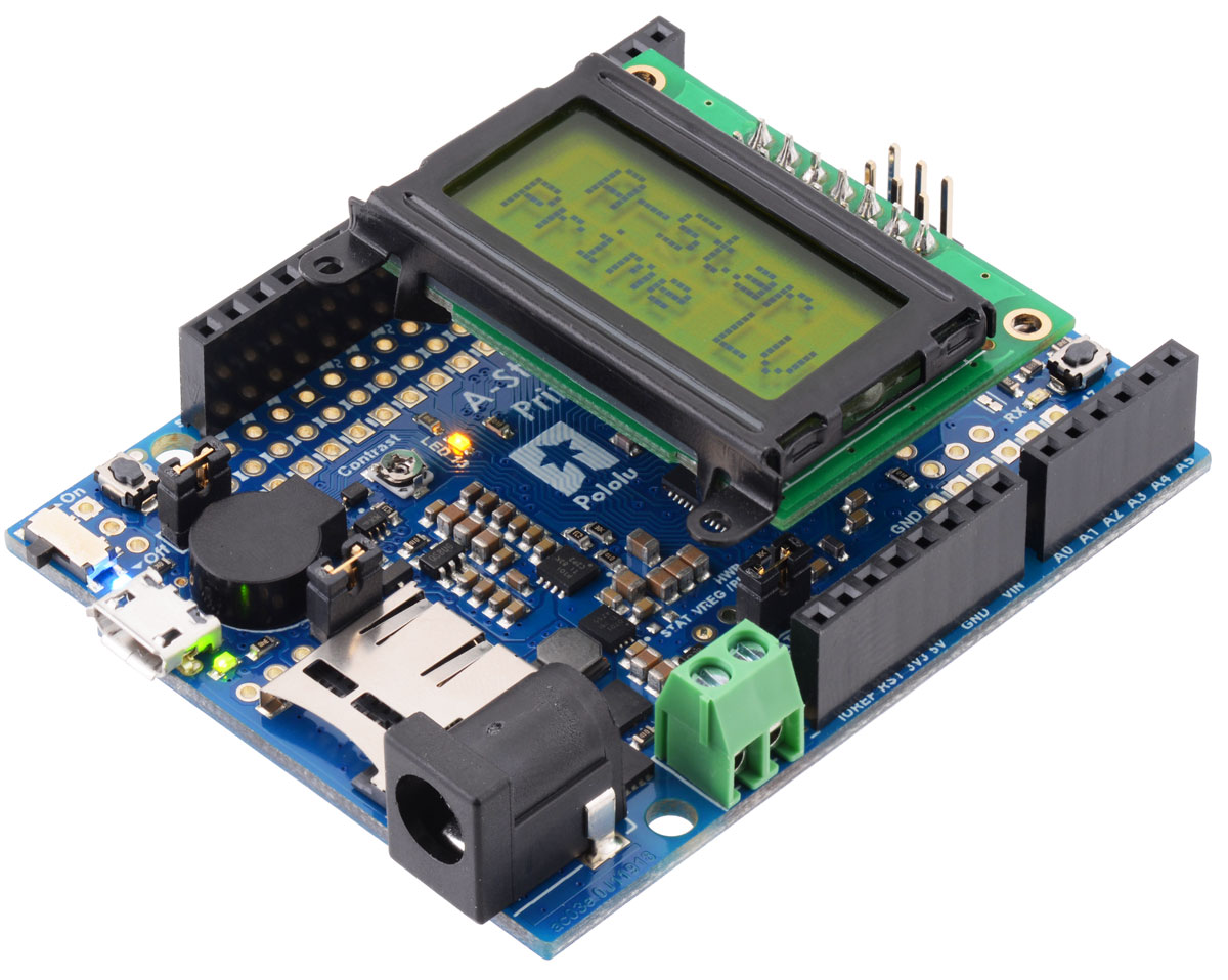
We have updated our A-Star 32U4 Prime LV with a new regulator that offers a wider operating voltage range and increased current capabilities. For those of you not already familiar with our A-Star 32U4 Primes, they are a series of ATmega32U4-based, USB-programmable controllers with integrated regulators that offer operating voltage ranges not available on typical Arduino-compatible products; this new “LV” variant features an improved buck-boost converter that enables efficient operation from 2 V to 16 V power supplies (Note: it requires an input voltage of at least 3 V to start, but it can operate down to 2 V after startup). The A-Star Primes are arranged in the common Arduino form factor exemplified by the Uno R3 and the Leonardo, so they are compatible with many Arduino shields, including all of the Arduino shields we carry.
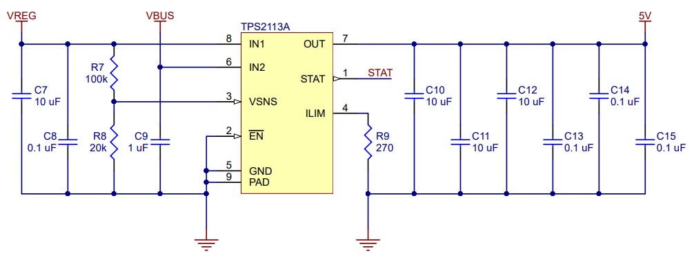
In addition to the increased input voltage range for the new A-Star Prime LV, the new regulator also provides more current. The graph below shows the current available on the new LV (ac03e) in blue compared to the old LV (ac03b) in purple. It is important to note that to use the full current available on the new A-Star Prime LV, you must connect to the VREG pin on the board and not the 5V ouput pin. The 5V output pin is limited to about 1.9 A because of the TPS2113A power multiplexer that makes up the board’s power selection circuit (a feature that sets the A-Star Primes apart from competing products). The power multiplexer decides whether the board’s 5 V supply is sourced from USB or an external supply via the regulator, allowing both sources to be connected at the same time and enabling the A-Star to safely and seamlessly transition between them. The multiplexer is configured to select external power unless the regulator output falls below about 4.5 V. If this happens, it will select the higher of the two sources, which will typically be the USB 5 V bus voltage if the A-Star is connected to USB. More information about the multiplexer can be found in this section of the A-Star 32U4 user’s guide under the Power heading.
|
|

The original version of the A-Star Prime LV, which operates from 2.7 V to 11.8 V, is now on clearance for 40% off! If you don’t need the increased output current and wider voltage range the new board offers, the previous version is still a great programmable controller to consider. Both the new and original A-Star Prime LVs come in multiple configurations. The complete selection of both versions can be found in the related products list below.
Related products


Video of Caesar, the first-place rover of the 2019 Indian Rover Challenge
The first-place winner of the 2019 Indian Rover Challenge, Team Anveshak from IIT Madras, sent us a link that shows their rover in action! The video is their submission to the 2019 University Rover Challenge (URC) System Acceptance Review (SAR), which is a major qualification round for participating in the URC finals. Good luck with SAR qualifications, Team Anveshak!
We first blogged about Team Anveshak’s rover back in January. For more information on the rover and the competition, including pictures, check out that post!
New product: 24V Step-Up/Step-Down Voltage Regulator S18V20F24
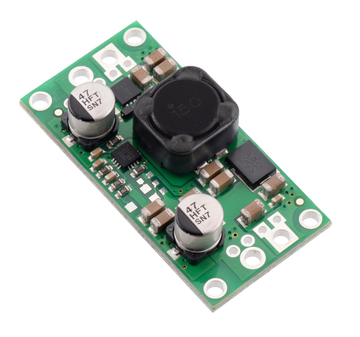 |
The 24V Step-Up/Step-Down Voltage Regulator S18V20F24 is the newest addition to our line of S18V20x step-up/step-down voltage regulators.
This 24 V fixed-voltage version is a minor modification of the 9 V to 30 V adjustable version we have been making for years. We can make custom-voltage versions of most of our regulators, and this particular unit was initially one of those customizations we routinely offer. However, since 24 V seems like it might be common enough to be interesting to other customers, we have made it a stock product. Since we assemble these at our Las Vegas, Nevada facility, we can often make simple customizations that only require component changes within a few days. Besides changing output voltages on regulators, these changes could include changing LED colors, omitting components such as pull-up or pull-down resistors, and substituting components with higher temperature ratings or better tolerances. (We offer more involved customizations that require modified board layouts or new firmware features, but those take longer and have higher up-front engineering costs.)
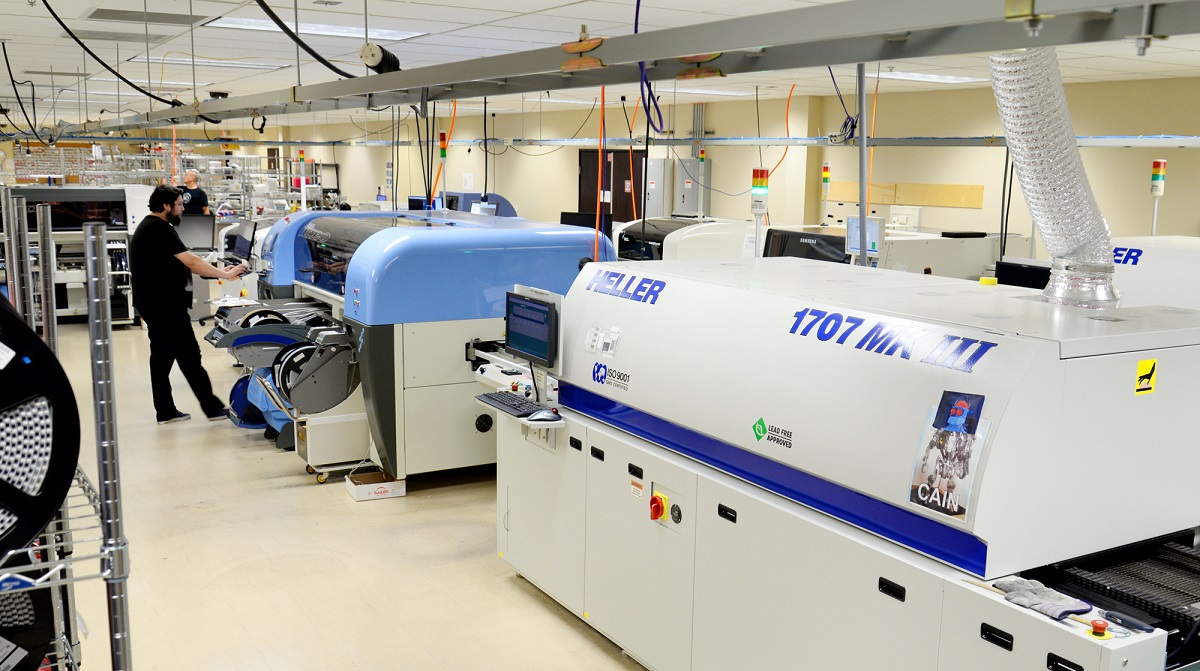 |
Pololu electronics manufacturing area with multiple pick and place lines. |
|---|
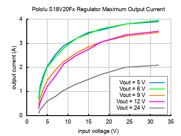
For those of you interested in the details of the actual product, the S18V20F24 efficiently produces a fixed 24 V output from input voltages between 3 V and 30 V while allowing a typical output current of up to 2 A when the input voltage is close to the output voltage. Its ability to convert both higher and lower input voltages makes it useful for applications where the power supply voltage can vary greatly, as with batteries that start above but discharge below the regulated voltage. Other features include integrated reverse-voltage protection, over-current protection, over-temperature shutoff, and under-voltage lockout.
|
|

Alternate versions of this regulator include a fixed 5 V, 6 V, 9 V, or 12 V output or an adjustable 4 V to 12 V or 9 V to 30 V output. Our full selection of regulators and power supplies can be found here.
Related products


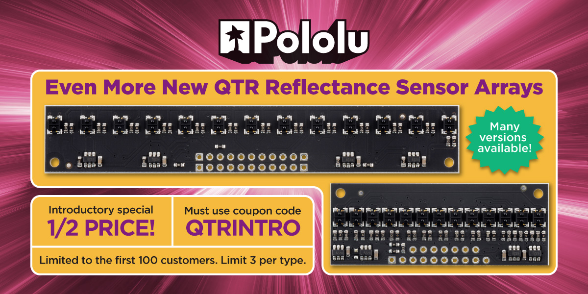
New products: 16 more QTR reflectance sensor arrays
Our rapidly growing selection of new QTR sensors now includes high-density (HD) versions with 13 and 25 channels, and medium-density (MD) versions with 7 and 13 channels. These QTR sensors are well suited for applications that require detection of changes in reflectivity. This change in reflectivity can be due to a color change at a fixed distance, such as when sensing a black line on a white background, as well as due to a change in the distance to or presence of an object in front of the sensor. Just like the 16-channel medium-density arrays we released in December, the 13-channel medium-density modules use PCBs specifically designed for an 8 mm pitch that allow separate control of the odd and even emitters, which gives you extra options for detecting light reflected at various angles. They have the same board dimensions (101 × 16.5 mm) and mounting hole locations as the high-density (4 mm pitch) 25-channel arrays, but the pinout is different.
|
|
||
|
|
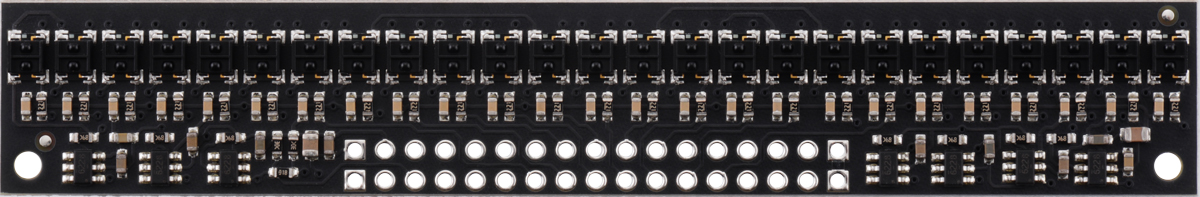
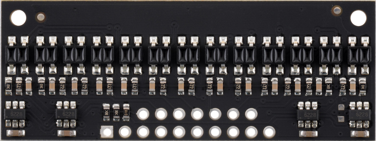
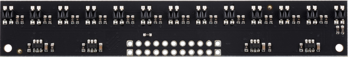

Each of these is available with two sensor options—traditional QTR and high-performance, low-current QTRX—and with analog or digital (RC) outputs, making 16 new products in all. Check out the QTR reflectance sensor category to see our full selection of new-style QTRs with black PCBs, which now stands at 96 varieties, and don’t forget to use our QTR introductory promotion to get 50% off any of these new sensors! (Limited to the first 100 customers who use coupon code QTRINTRO, limit 3 per item per customer.)
Related products


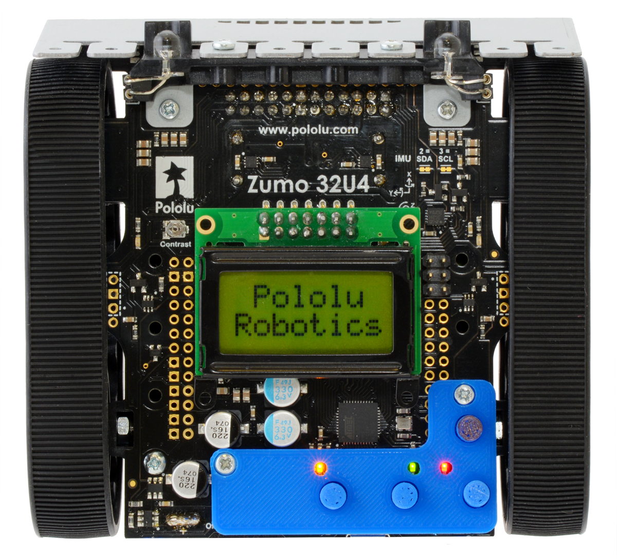
Bigger 3D printed buttons for the Zumo 32U4
 |
Mount Holyoke College professor Peter Klemperer designed a custom add-on for the Zumo 32U4 to give easier access to the user pushbuttons. Peter made the bigger buttons as a response to some of the students in his classes finding it difficult to use the small onboard pushbuttons.
The design even has small cutouts so you can still see the indicator LEDs. To add the adapter plate to the Zumo chassis, you can use two #2 screws and nuts (7/16 inch length screws worked great for me). The easy-to-print STL files along with the Fusion 360 files are available on Peter’s GitHub repository for the project, and you can find more information on Peter’s blog post on his website.
If you print your own bigger buttons for your Zumo 32U4 be sure to let him (and us!) know; we would love to see some pictures! Here’s a shot of the one I printed out for my personal Zumo 32U4:
 |
Related products


Firmware update for Tic Stepper Motor Controllers, with new features including limit switches and homing
 |
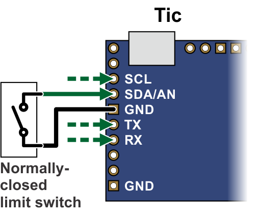 |
Connecting a limit switch to the Tic (SCL, SDA, TX, and RX pins). |
|---|
To go along with last week’s release of the Tic T249, we have also released a new version of the Tic firmware (version 1.06) for all Tic stepper motor controllers that adds several new features.
By popular demand, this new firmware version adds support for limit switches: any of the Tic control pins (SCL, SDA, TX, RX, or RC) can be configured as a digital input for a forward or reverse limit switch. When the limit switch is active, the Tic abruptly shuts down any movement in the specified direction, but allows the stepper motor to move in the other direction. You can use limit switches to help prevent your system from leaving its desired range of motion.
If you configure a limit switch, you can use the Tic’s new homing procedure. The new “Go home” command, which is available over serial, I²C, and USB, starts the homing procedure. The Tic will move in the direction specified by the command until it hits a limit switch for that direction. Then it will change directions, move until the limit switch deactivates, and set its current position to 0. The stepping speeds used by the Tic during the homing procedure are configurable.
You can also use the homing feature automatically, without sending a command. If automatic homing is enabled, the Tic performs the homing procedure whenever it is being commanded to go to a specific position but it is uncertain of its current position (e.g. immediately after motor power is applied). This feature can be handy if you are controlling the position of your stepper motor using an RC, analog, or quadrature encoder signal.
We have added a new section to the Tic user’s guide with detailed instructions for setting up limit switches and homing.
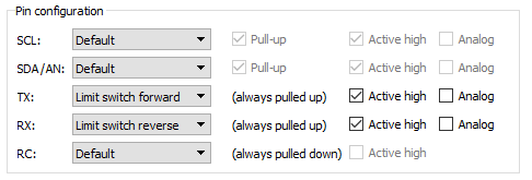 |
Example pin configuration for a Tic with limit switches. |
|---|
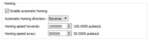 |
New homing settings added in Tic firmware version 1.06. |
|---|
The new firmware version also adds several features to the Tic’s TTL serial interface that make it more usable in systems with large numbers of Tics and in half-duplex serial busses. Specifically, it adds support for an alternative device number so any Tic can optionally be addressed by two different device numbers, and it adds an option to enable 14-bit device numbers so you can have more than 128 devices on a serial bus. The new firmware version also has an option to encode its serial responses using only bytes between 0 and 127, which can be useful in setups where the serial response from one Tic will be seen by other Tic devices, and you don’t want it to be misinterpreted as a command. We also implemented several changes to make the Tic less susceptible to noise on the serial lines, and you can now enable CRC bytes for serial responses sent by the Tic so that you can confirm the data you received matches what the Tic sent.
The Tic T249 was released with the latest firmware, so it has all of these new features, and we will be upgrading our existing Tics to this firmware version as we manufacture more. To gain access to these new features on your existing Tic controllers, you can download the latest configuration software and upgrade your device’s firmware to version 1.06. For more information, see the firmware upgrade instructions in the Tic user’s guide.
Related products


Macro photography using Tic stepper motor controllers
|
|
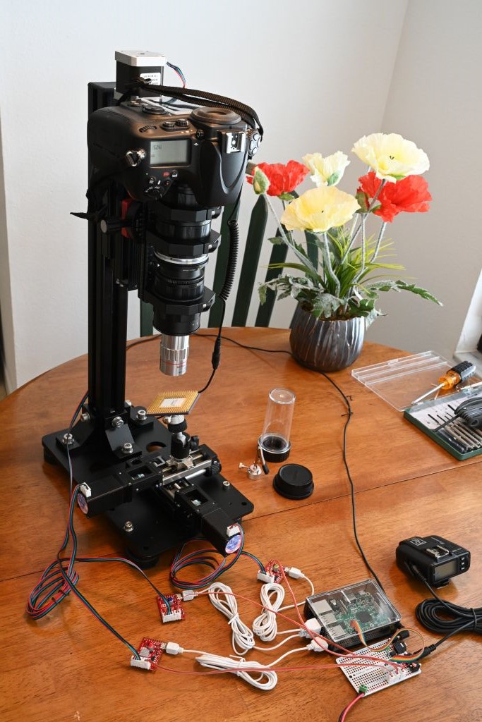
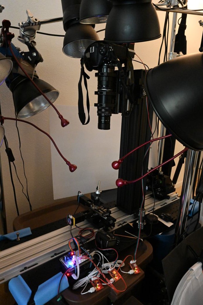
Forum member Mike is using our Tic stepper motor controllers in his automated stack & stitch image acquisition systems, which he has been using to get extremely high resolution images of various integrated circuits. Each system uses linear rails and stepper motors to properly align the camera/lens and the object to be photographed. Two stepper motors position the subject and a third adjusts how close the camera is to the subject. A Tic T500 controls each stepper motor and each Tic connects to a USB port on a Raspberry Pi 3B or Raspberry Pi 3B+, which acts as the main computer. Afterward, Mike stacks the images with Zerene Stacker and stitches them together with Photoshop. Some of his image sessions capture as many as 6000 individual images that are used to produce a single 300 megapixel image!
 |
Zooming in on a stack & stitch test image. |
|---|
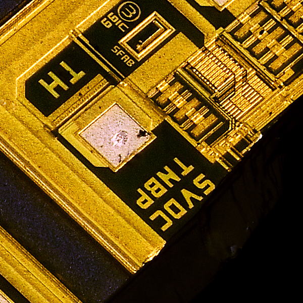 |
A close-up view of a stack & stitch test image. |
|---|
You can find more information about Mike’s stack & stitch image acquisition systems (like what specific mechanical hardware he is using) in this forum post. Also, to see and/or download a set of high resolution pictures taken with those setups, follow this link.

New product: Tic T249 USB Multi-Interface Stepper Motor Controller

I am excited to announce the release of the Tic T249 USB Multi-Interface Stepper Motor Controller, the fourth model in our line of Tic Stepper Motor Controllers. The Tic T249, which is based on the TB67S249FTG IC from Toshiba, features a broad 10 V to 47 V operating range and can deliver up to approximately 1.8 A per phase without a heat sink or forced air flow, making it our highest-power Tic yet. In addition to the array of high-level features offered by the other members of our Tic family, the Tic T249 offers access to several innovative features of the TB67S249FTG driver. Continued…
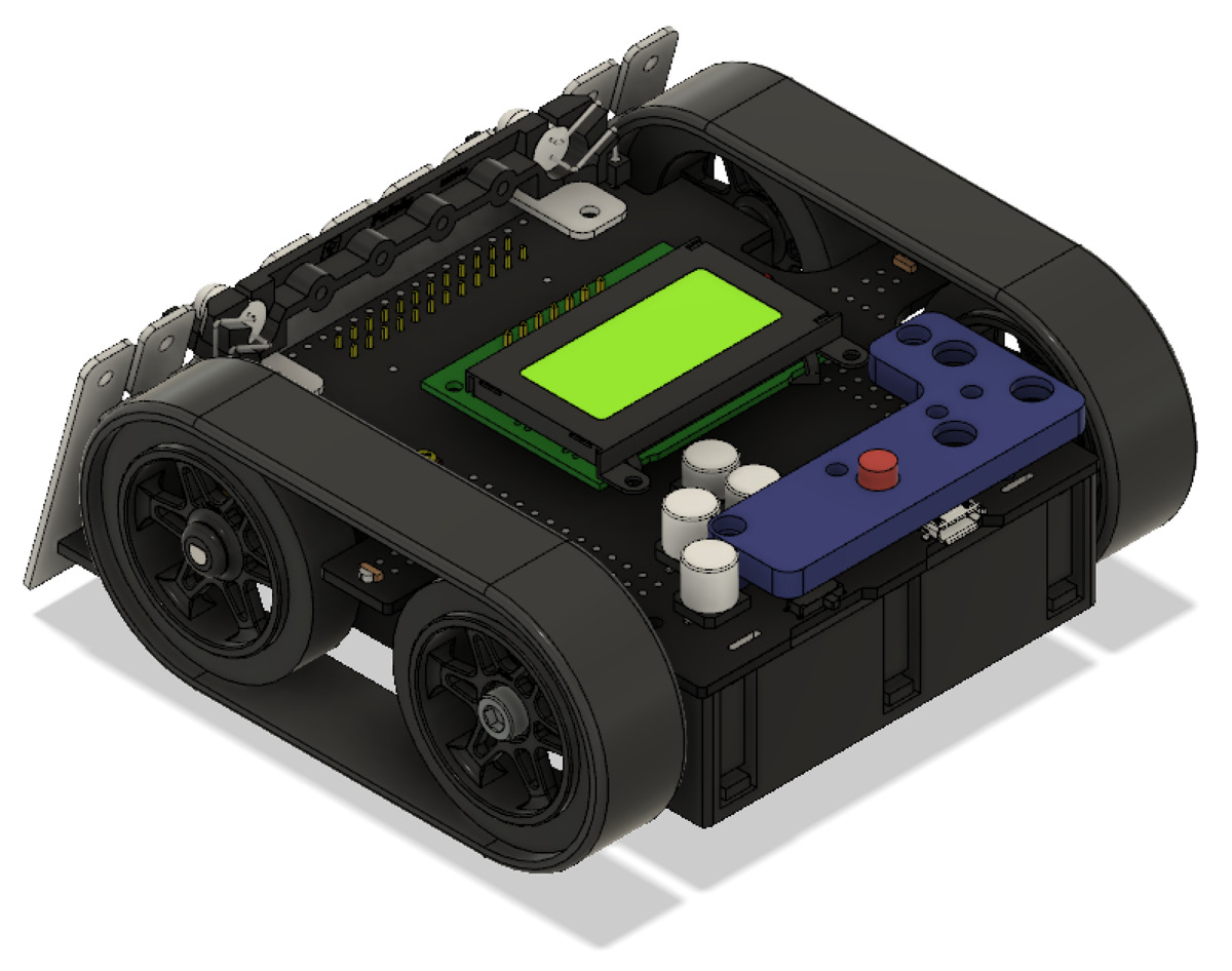
Rover team from IIT Madras places first in Indian Rover Challenge
 |
Congratulations to Team Anveshak from IIT Madras, who took first place at the 2019 Indian Rover Challenge! The IRC is a robotics and space exploration-based competition for college students. Participating teams design and build a Martian rover prototype and use that rover to compete in various tasks like obtaining soil samples, operating electrical racks, and picking up and delivering objects.
|
|
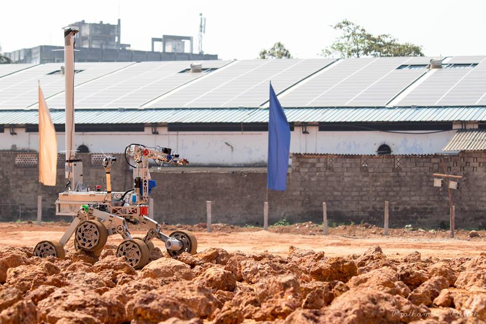
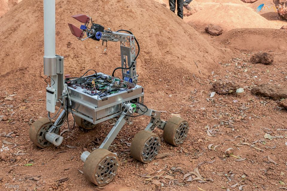
Team Anveshak’s winning rover, Caesar, uses 10 different Pololu products! We are especially excited to hear that their rover prominently features our newer G2 High-Power Motor Driver 24v13 and TB9051FTG motor drivers, using 9 of each of those boards.
We love seeing all the awesome things like this that people are doing with our products! For a more complete list of the Pololu parts used in Caesar, check out the related products listed below. If you want to learn more about the team, check out their website.
8 March 2019 Update: See a video of Caesar in action here.
Related products


Home | Forum | Blog | Support | Ordering Information | Lists | Distributors | BIG Order Form | About | Contact
© 2001–2026 Pololu Corporation


