Pololu Blog »
New Tic T500 revision to address problem with missed steps
One of the fun things you learn as an engineer is that physically laying out a circuit requires a lot more than simply confirming it matches the schematic. In practice, there are many more things to think about, and if you’ve seen datasheets with layout guidelines or recommendations, you’re probably aware of some of them. (Thermal considerations, adequate decoupling, minimizing parasitic inductance and capacitance…) What’s more, these considerations are often in conflict (e.g. is it better to have the decoupling capacitor closer to the IC or to have a wider trace for that high-current path?), and trouble can arise if you don’t correctly assess their relative importance. That is what happened to us with our Tic T500 stepper motor controller, where the location of a specific decoupling capacitor ended up being far more significant than we had anticipated.
 |
The problem with our original Tic T500—as we found after a customer reported having issues—was that the driver sometimes seemed to reset and lose its position in its indexing table, causing the stepper motor to stutter and skip steps. This only happened under certain conditions, and it appeared to occur more often with low-resistance and low-inductance motors, high input voltages, and high current limits.
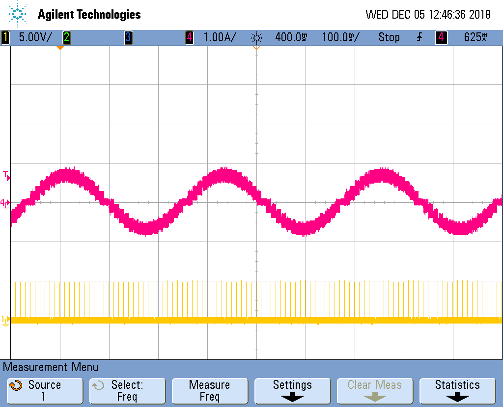
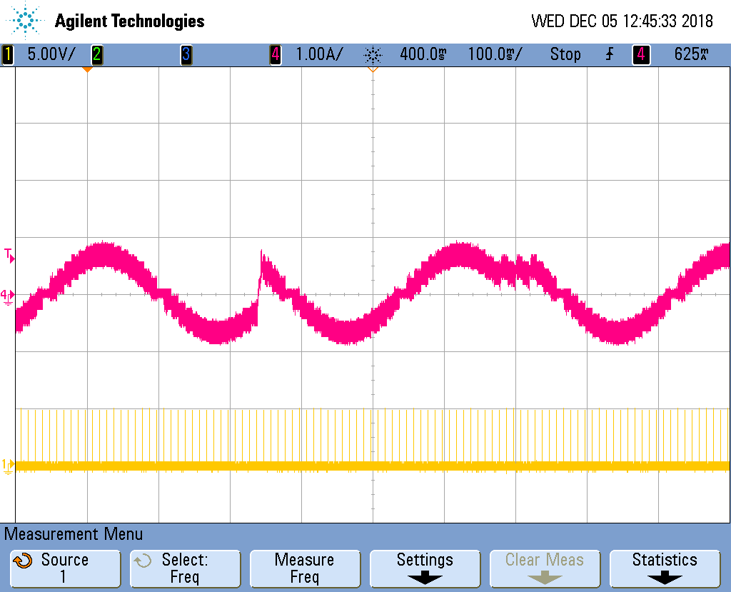
These oscilloscope captures show the difference between normal operation and the problematic behavior on the Tic (pink is the current in one motor coil, yellow is the voltage on the driver’s STEP pin). But even without a scope, it’s apparent when the problem occurs: you can see, hear, and feel the motor jolting and moving erratically.
|
|
Unlike blatant mistakes in the design of a board that prevent it from working at all, this type of problem can be difficult to detect since a very specific combination of factors needs to be present for it to occur. When we develop a new board that might be used in a wide range of conditions, we try to cover as much of that range as possible in our testing. For example, each of our switching voltage regulator designs goes through a characterization process that involves sweeping over the full input voltage range at many different loads while looking for instability in its output voltage. Some problems are resolved by more careful selection of component values, but occasionally, we have to do additional board revisions, sometimes even going to higher layer counts, before making a product available for sale. Unfortunately, we did not encounter the problem with the Tic T500 in our initial testing.
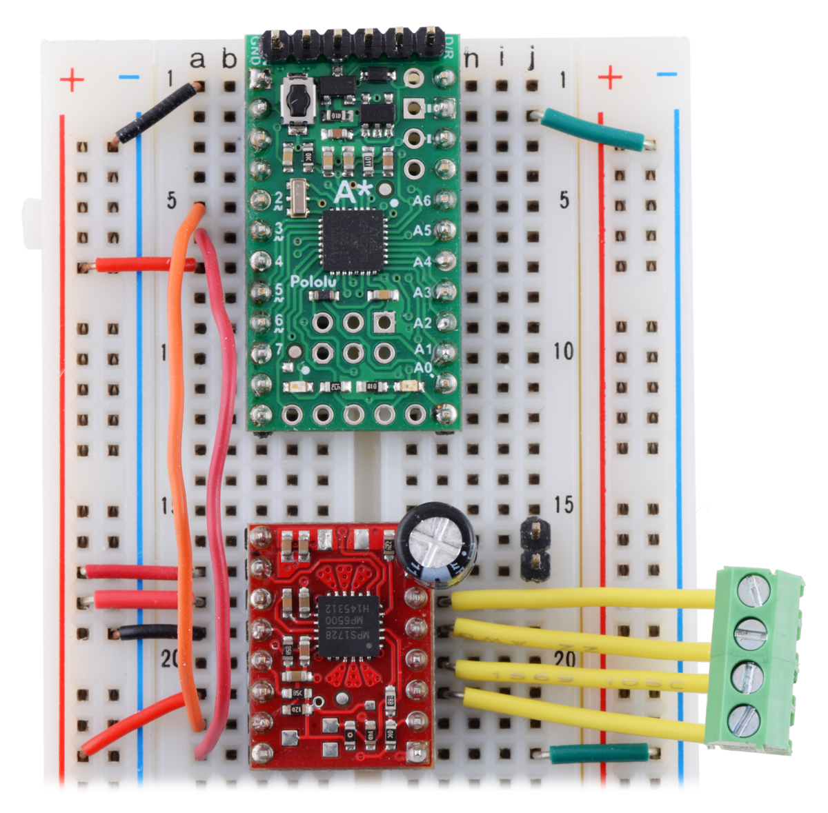
Our first indication that something might be wrong came last month when someone posted on our forum about some strange behavior they were observing, and we started trying to replicate the issue here. In an effort to understand what was happening, we duplicated the design of the Tic using an A-Star and an MP6500 carrier board (which has the same driver the Tic T500 uses) on a solderless breadboard. The expectation was that the relatively crude breadboard layout would make the problem worse by adding all sorts of stray capacitance, inductance, and contact resistance, and that would give us some better insight, but we were unable to reproduce the problem with this setup. This pointed to the issue being something subtle about the layout of the Tic rather than some fundamental error in its routing.
 |
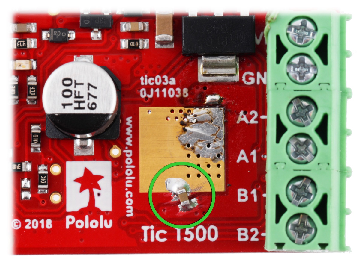
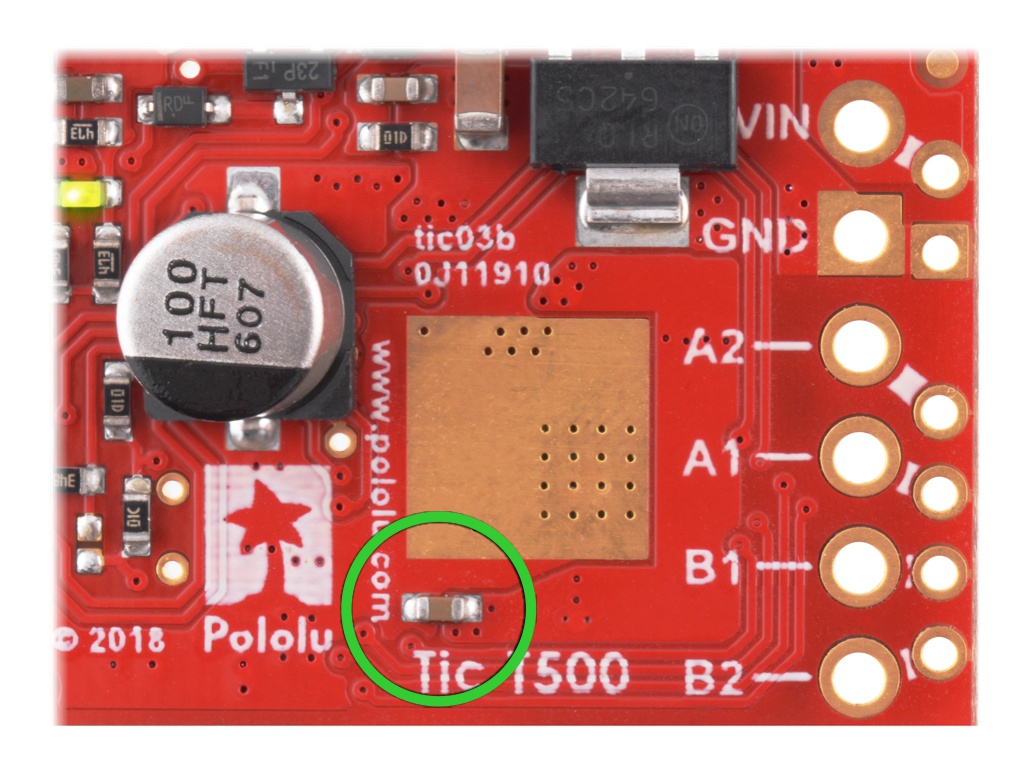
After trying various different modifications to the Tic T500, we found that we could reduce or eliminate the resets and skipped steps by adding extra capacitors near one of the driver’s VIN (motor voltage input) pins. We subsequently revised the PCB to include footprints for those additional capacitors, and that seems to have solved the problem. The left picture below shows the original PCB with a capacitor we added while tracking down this problem, and the right picture shows the new revision with that capacitor added in a classier way:
|
|
This picture indicates where all the VIN capacitors and pins are on all three boards:
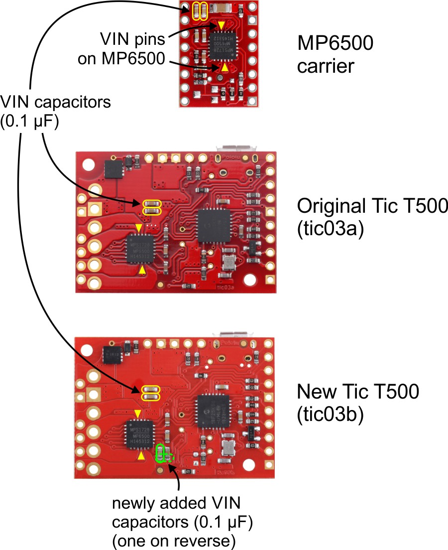 |
Surprisingly, the new capacitor on the top side of the board (indicated by the dashed outline) actually seems to be much more effective, which is unfortunate, because it limits how big of a heat sink you can add there. Even though it is basically in the same place as the one visible on the bottom side on the board, the top-side capacitor alone was enough to prevent the resetting and skipping in our tests, while the bottom-side one alone did not.
One reason we designed our basic MP6500 carrier first was to make sure we had a good understanding of the driver before designing it into more complicated products, so it was more than a little frustrating when the same basic layout that worked on the carrier didn’t work on the Tic. Initially, we assumed the difference was due to the MP6500 carrier having a 4-layer PCB compared to two layers on the Tic T500, which generally lets everything be better connected, and that could still be a big part of the answer. However, while making the comparison image above, we realized the MP6500 IC is actually rotated 180° on the carrier compared to the Tics (the text on the IC is upside down on the carrier and right side up on the Tics). So the two 0.1 μF capacitors on the carrier are closer to the “bottom” of the chip, while the two on the original Tic are closer to the “top”. If the chip is sensitive to a lack of capacitance near the bottom VIN pin, maybe that helps explain the behavior we saw!
Even though we expect it to be somewhat rare for customers to encounter this problem on the Tic T500 (to my knowledge, we have only heard of two cases), we want to make sure our products represent our best work, so we’ve pulled all our stock of the original boards (tic03a), and we’re offering free replacements for any that have already been sold. If you bought a Tic T500 from us directly, we will be emailing you to let you know how to replace it with an updated board (tic03b), or you can just contact us directly for a replacement. We will also be working with our distributors to get them replacement units for any customers that got the original Tic T500.
Related products


-

New product: STSPIN220 Low-Voltage Stepper Motor Driver Carrier with 1/256 microstepping
- 16 January 2019I am happy to announce our first new product of 2019, a carrier board for the STSPIN220 stepper motor driver, which operates all the way down to...
-
TI Robotics System Learning Kit (TI-RSLK) in EDN’s hot 100 products of 2018
- 24 January 2019EDN recently released their hot 100 products of 2018, and we are excited to share that the TI Robotics System Learning Kit (TI-RSLK),...
5 comments

I would like to get replacements for the Tic-500 I have purchased directly from Pololu.
I believe I have purchased 8 (maybe 9) Tic-500s.
Best,
Mike Wyatt


I am trying to do my own motor driver using the driver MP 6500 from pololu, i would like to keep using the software from Pololu, but i have a problem with the conections from the pin DIR and STEP to the microcontroller, i am using the PIC 18f25k50,
as I said i would like to keep using the software for the driver TIC T500, I do not know if it is possible to change the pin conection in the software or it is not possible.
Best,
Israel

It is not clear to me what exactly you are trying to do, but this is not an appropriate place to answer detailed questions or get into troubleshooting. You might consider posting a request for help on our forum and include a lot more details about what you are doing. Alternatively, you can email us at support@pololu.com.
Brandon
Post a comment


Home | Forum | Blog | Support | Ordering Information | Lists | Distributors | BIG Order Form | About | Contact
© 2001–2026 Pololu Corporation
