Pololu Blog » Posts tagged “new products” »
Posts tagged “new products” (Page 21)
You are currently viewing a selection of posts from the Pololu Blog. You can also view all the posts.
Popular tags: community projects new products raspberry pi arduino more…
New product: Pololu Dual MC33926 Motor Driver for Raspberry Pi
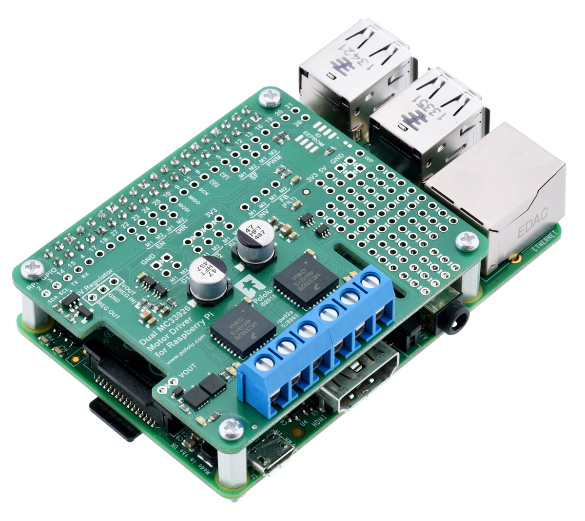 |
The Pololu Dual MC33926 Motor Driver for Raspberry Pi is our latest offering designed to help you build a robot around the powerful and versatile Raspberry Pi single-board computer. It features a pair of Freescale MC33926 motor drivers, each capable of supplying a motor with up to 3 A continuous (5 A peak) at voltages from 5 V to 28 V. This makes it a good choice for driving bigger things like our 25D and 37D motors and even linear actuators.
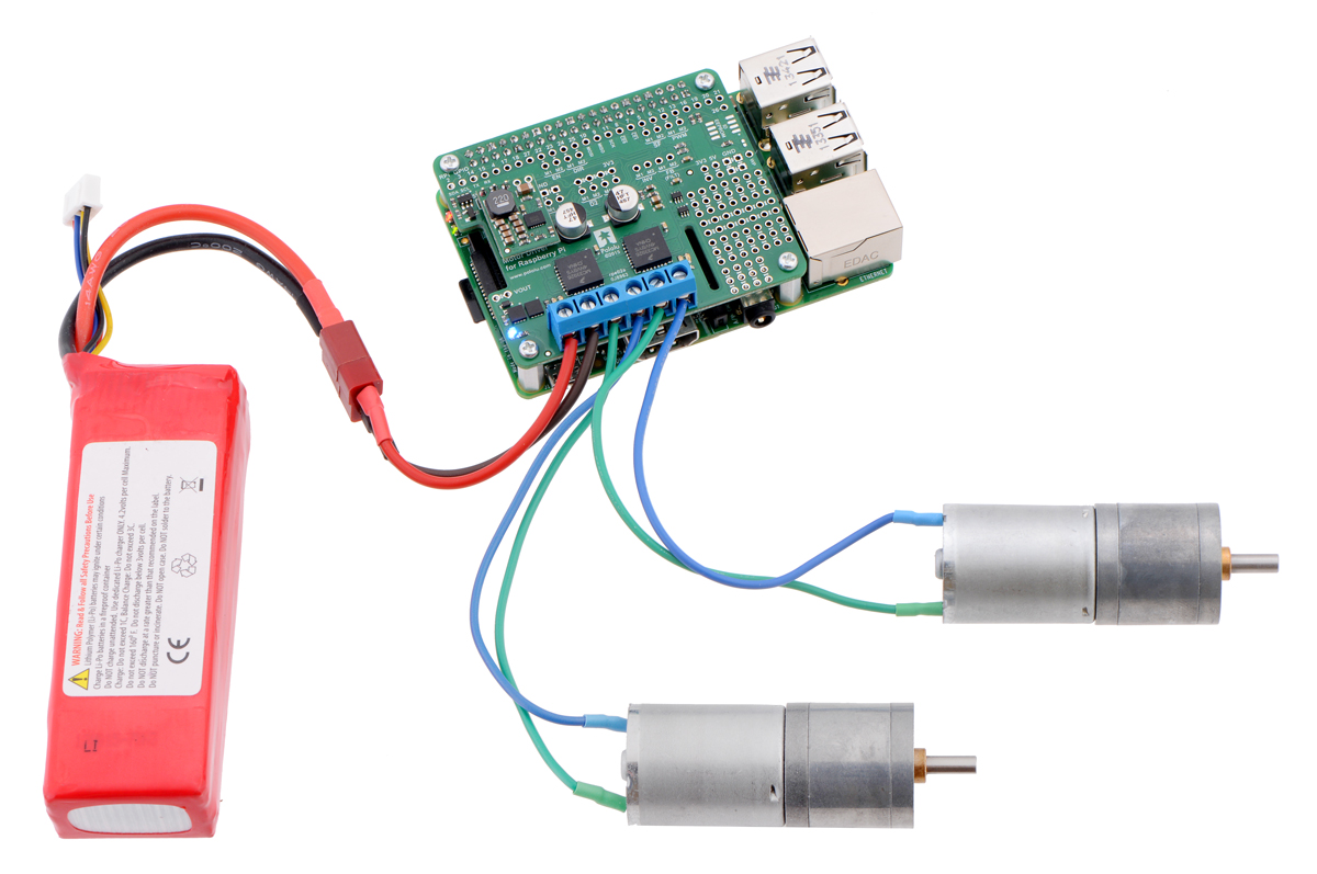 |
Driving motors with a #2756 dual motor driver on a on a Raspberry Pi Model B+ or Pi 2 Model B. A step-down regulator provides 5 V to the Raspberry Pi. |
|---|
We particularly like using the MC33926 because of its robustness: it can withstand voltage transients up to 40 V, and it has a current regulation feature that actively limits the output current to a safe amount. Furthermore, the driver automatically lowers the current limit as its temperature increases, allowing it to gracefully reduce the motor current instead of abruptly shutting down.
This add-on board is a step up from the relatively minimal, lower-power DRV8835 motor driver expansion we released last year, but it is just as easy to use. Our Python library helps you quickly get your motors running with the board’s default pin mappings, which use logic gates to enable drive/brake operation of the MC33926 drivers with only two control pins per motor.
Additional inputs and outputs on the MC33926 drivers are exposed for advanced users who want to make use of other configurations and control methods, and a small prototyping area on the side of the board provides a convenient space for adding custom circuits. As with the DRV8835 board, you can optionally connect a voltage regulator (not included) to power the Raspberry Pi from the motor power supply.
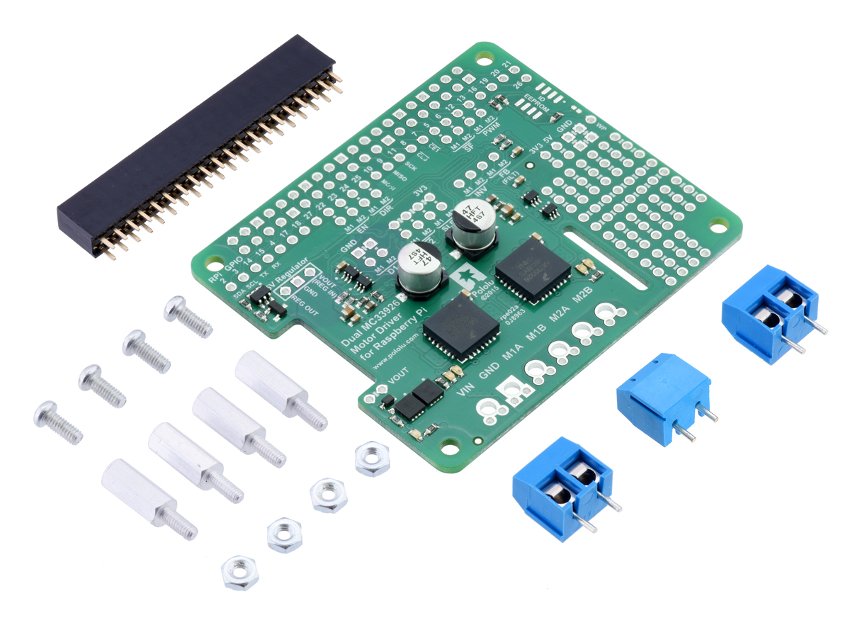
The motor driver board is available in two versions:
- a partial kit, with connectors included but not soldered in
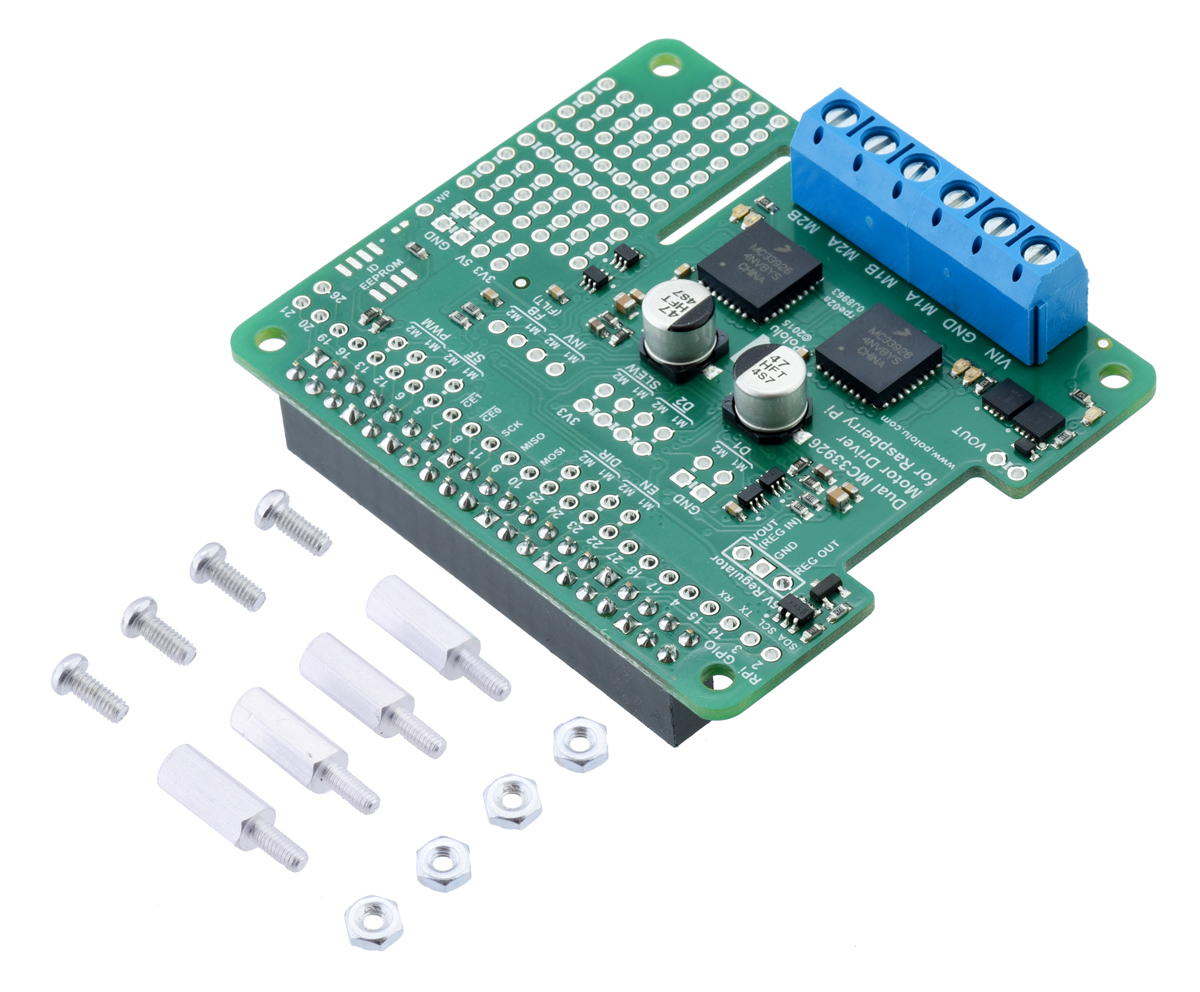
- fully assembled, with the female header and terminal blocks soldered to the board
|
|
If you’re familiar with other Raspberry Pi add-on boards, you might find it unusual that we are not calling this board a “motor driver HAT”. In fact, it meets most of the requirements needed to qualify as a Raspberry Pi HAT (Hardware Attached on Top): it matches the HAT mechanical specification, and it even includes the recommended ideal diode circuit, allowing the optional regulator and the Raspberry Pi’s usual USB Micro-B power supply to be safely connected at the same time.
The reason the board does not qualify as a HAT is the absence of an ID EEPROM. Such a component is intended to allow the Raspberry Pi to identify a HAT board and configure itself to work with that board. We spent some time looking into how an ID EEPROM might help make this motor driver expansion better or easier to use, and we made provision for adding one in the design of the PCB, but eventually we concluded that it seems to offer no substantial value for this kind of board. (We’ve even seen some similar HATs from other manufacturers that ship with a completely blank EEPROM!)
Automatic configuration might be useful for making the Raspberry Pi automatically load a Linux device driver for an I²C or SPI add-on, but since this motor driver expansion is controlled with direct manipulation of GPIO pins, the responsible program or library can easily set up the pins itself before it begins driving and reading them. Other use cases, like enabling the Raspberry Pi to detect whether the HAT is connected and potentially distinguish between different versions of the HAT, would require much more complex support software to take advantage of while being of questionable benefit.
As a result, we’ve decided to omit the ID EEPROM from the board, even if that means it doesn’t meet the full HAT specification and shouldn’t be called a HAT. The EEPROM format specification still appears to be preliminary and subject to change, so it’s possible that future Raspberry Pi updates will make the EEPROM more useful; if so, we will likely reconsider the decision not to populate the EEPROM chip. However, if you think we’ve missed an argument for including an ID EEPROM now or have any other thoughts on its value, we’d be interested to hear your observations.
Related products


New products: APA102C-based addressable RGB LED strips
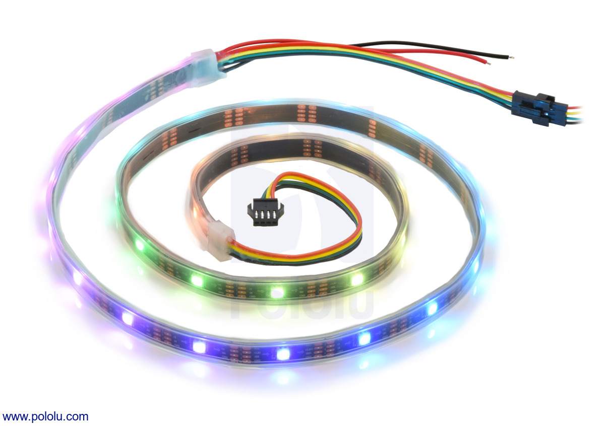 |
We’re excited to offer a series of APA102C-based addressable RGB LED strips to complement our existing WS2812B-based LED strips. Like the WS2812 strips, the new strips have connectors on both ends to make chaining easy, and they are available in the same six combinations of LED densities and lengths:
- 1 meter, 30 LEDs (30 LEDs/m)
- 2 meters, 60 LEDs (30 LEDs/m)
- 5 meters, 150 LEDs (30 LEDs/m)
- 1 meter, 60 LEDs (60 LEDs/m)
- 2 meters, 120 LEDs (60 LEDs/m)
- 0.5 meters, 72 LEDs (144 LEDs/m)
Like the WS2812B, the APA102C combines an RGB LED and driver into a single 5050-size package, allowing them to be packed as densely as 144 LEDs per meter, and each pixel can be individually addressed to give you full control over the color of each RGB LED. However, while the WS2812B uses a high-speed one-wire control interface with strict timing requirements, the APA102C has a standard SPI interface, with separate data and clock signals, that lets it work with a wide range of communication rates, making it much easier to control.
For example, it isn’t easy for a Raspberry Pi to generate a control signal with the exact timings that the WS281x requires. However, an APA102 only reads its data signal on the rising edge of its clock signal, and the Raspberry Pi controls both signals, meaning it is free to bit-bang data to the LEDs as slowly (or quickly) and as irregularly as it wants. Alternatively, it’s straightforward to use the SoC’s built-in SPI peripheral to drive APA102 LEDs. Of course, both the bit-banging and hardware SPI approaches can also be used on many other devices, including A-Stars and Arduinos.
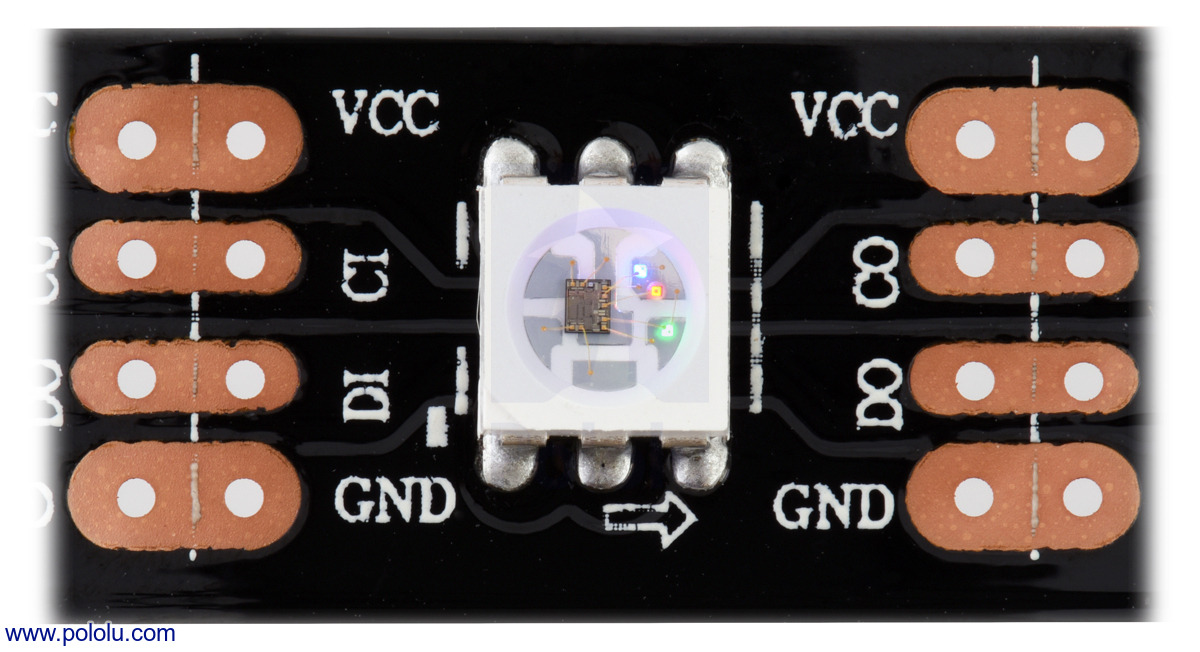 |
Close up of one segment of an APA102C-based LED strip, with the red, green, and blue LEDs on at a low brightness. |
|---|
The APA102C also offers a few other improvements over the WS2812B, including a color-independent brightness control that lets you easily adjust the intensity of each LED without changing its color. Also, the color channels on an APA102C are pulse-width modulated (PWM) at a much higher frequency, making it less susceptible to flickering on camera and more suited to persistence-of-vision (POV) applications.
For more information about our APA102C-based LED strips, see their product pages.
 |
Related products


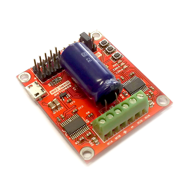
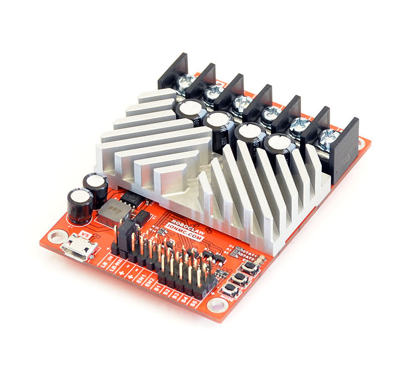
New products: RoboClaw 2x5A, 2x15A, and 2x30A motor controllers (V5)
We’re now selling the latest V5 versions of the RoboClaw 2x5A, 2x15A, and 2x30A dual motor controllers from Ion Motion Control. Like the previous V4 RoboClaws, they can drive a pair of brushed DC motors at voltages from 6 V to 34 V, but the 2x5A now has a USB serial interface (in addition to TTL serial, RC, and analog inputs) like its larger siblings, and the 2x15A and 2x30A have a new heat sink design that should improve cooling. We expect to have updated documentation for the new versions soon.
|
|
Related products


New products: 0.1″ (2.54 mm) screw terminal blocks
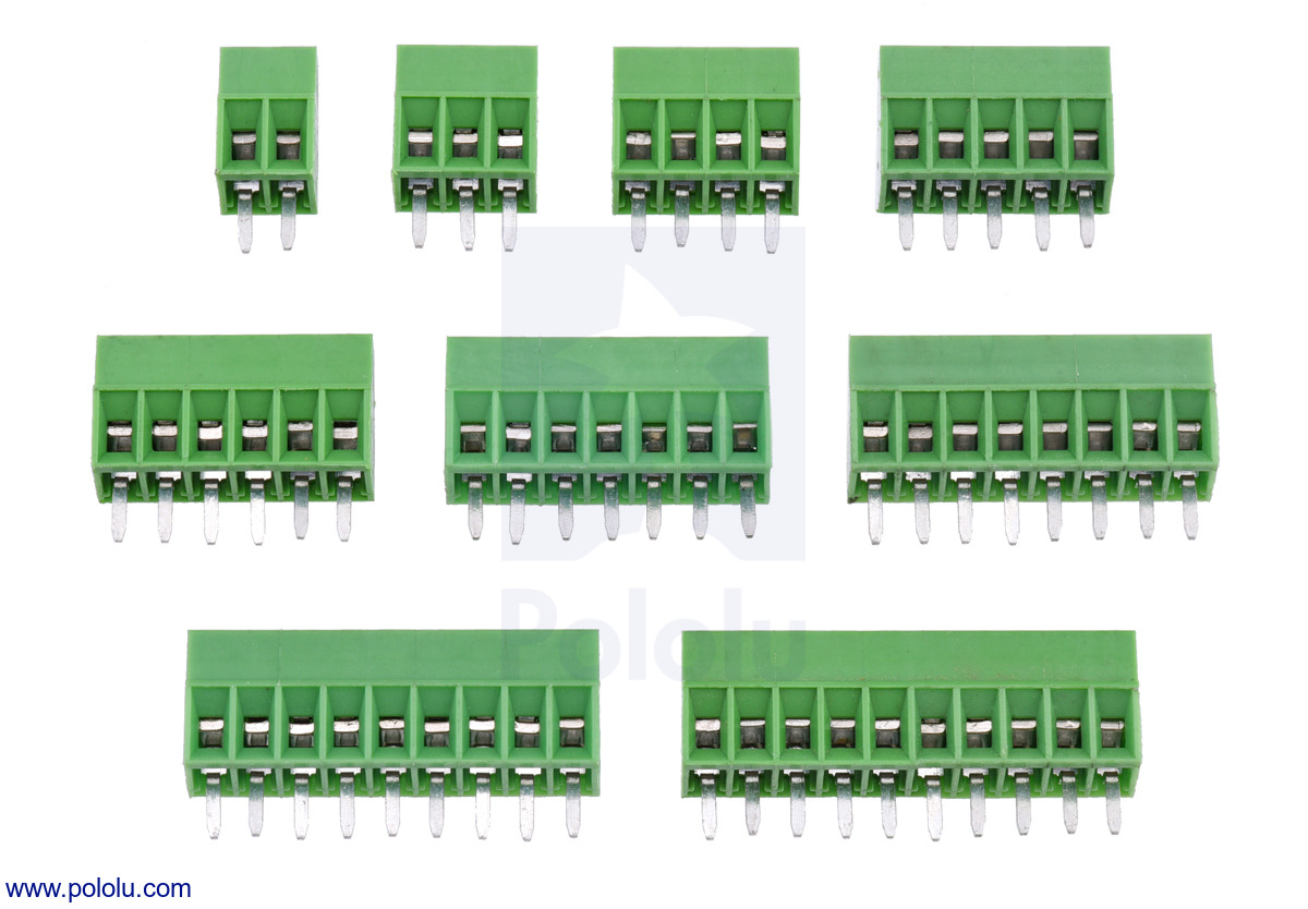 |
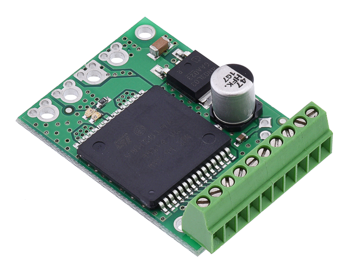
We are excited about our new 0.1″ terminal blocks because they can typically be soldered to PCBs in place of standard 0.1″ male and female headers, offering alternative board-to-wire connection options that can be especially convenient in cases where you know you will be dealing with stripped, unterminated wires. For example, the following picture shows an 8-pin terminal block spanning the control connections of a VNH5019 motor driver carrier:
 |
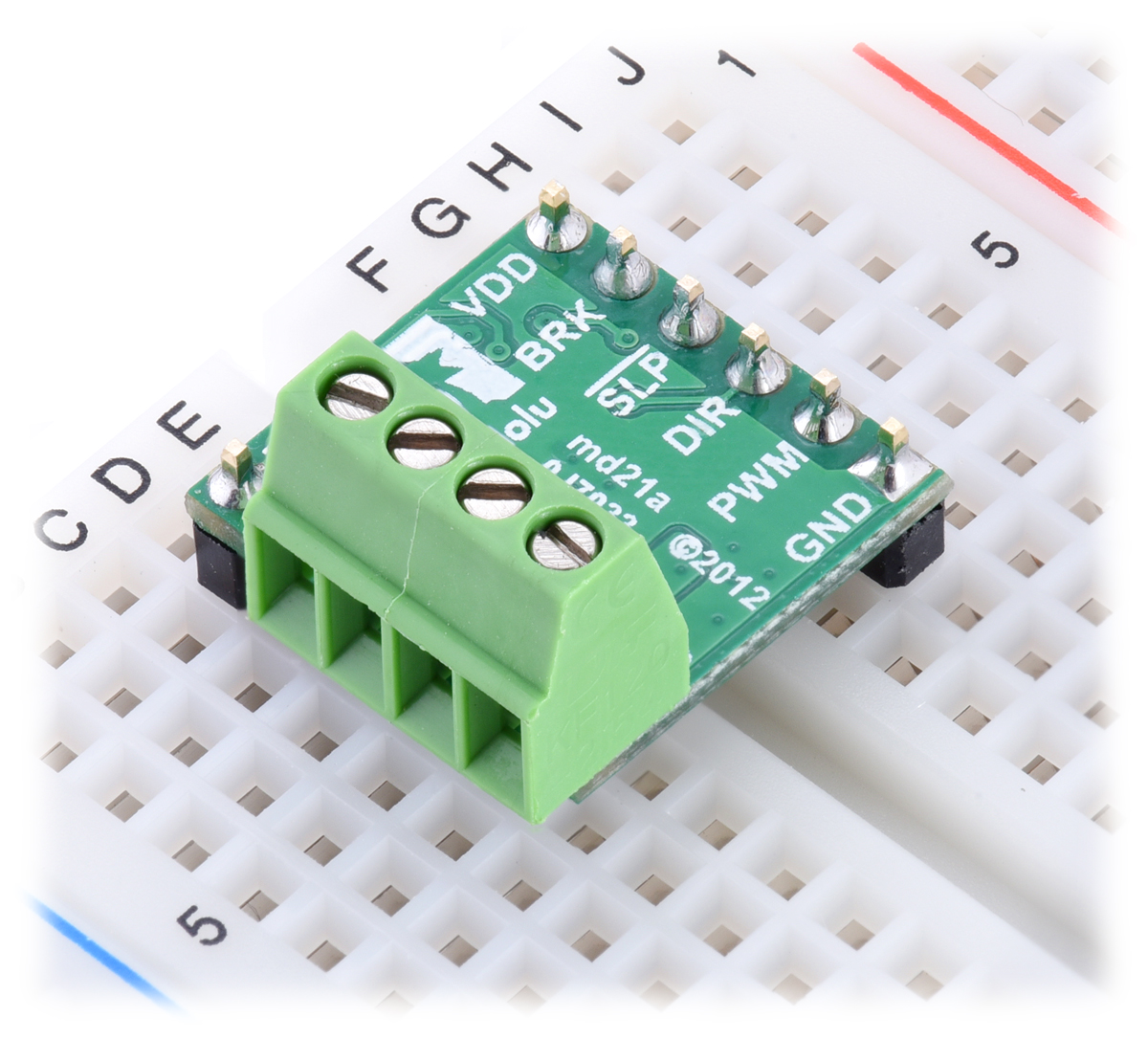
There are some low components (e.g. resistors and capacitors) near the motor driver’s 0.1″ holes, but the terminal block is able to comfortably sit on top of them. In cases where there is not sufficient clearance from tall, nearby components, it might be possible to use the terminal blocks on the bottom side of the PCB. The following picture is an example of this, with a 4-pin terminal block used for the motor and motor power connections of a DRV8801 motor driver carrier:
 |
And in case these pictures are giving the illusion of large PCBs rather than tiny terminal blocks, we have for your viewing pleasure a picture of these terminal blocks in a 0.1″ prototyping board (Adafruit’s Perma-Proto prototyping PCB) next to some standard 0.1″ male header pins:
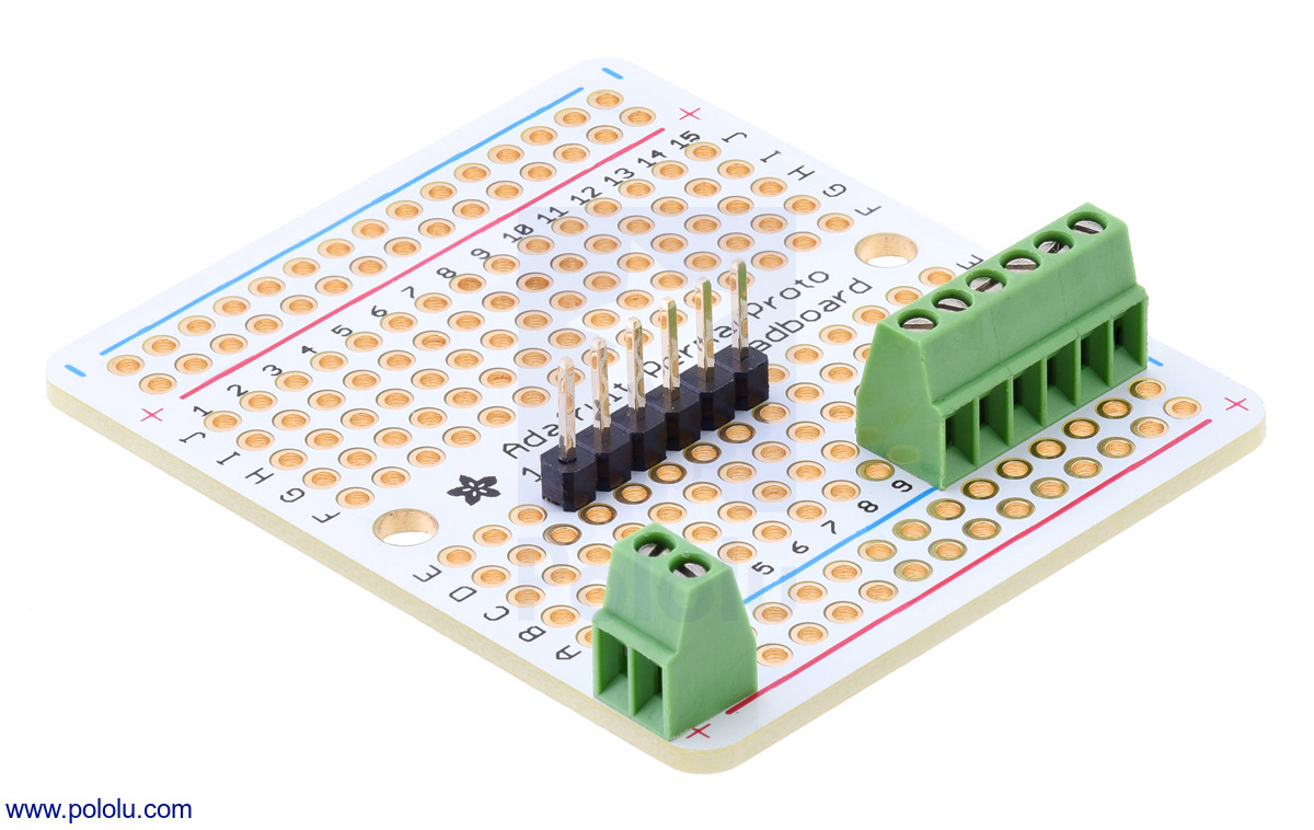 |
These terminal blocks cannot be combined into longer strips or placed side-by-side on a 0.1″ grid, so you will need to get the exact lengths required by your application. Fortunately, we have nine lengths to choose from, from two pins through ten pins!
Related products


New product: shorter 12 mm hex wheel adapter for 6mm shafts
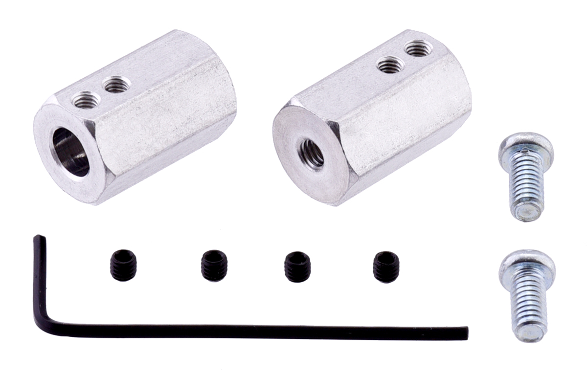 |
We now have a shorter (20 mm) 12 mm Hex Wheel Adapter for 6 mm Shaft as an alternative to our original 35 mm extended version. These adapters work well with our 37D mm metal gearmotors, allowing you to use them with many common hobby RC wheels.
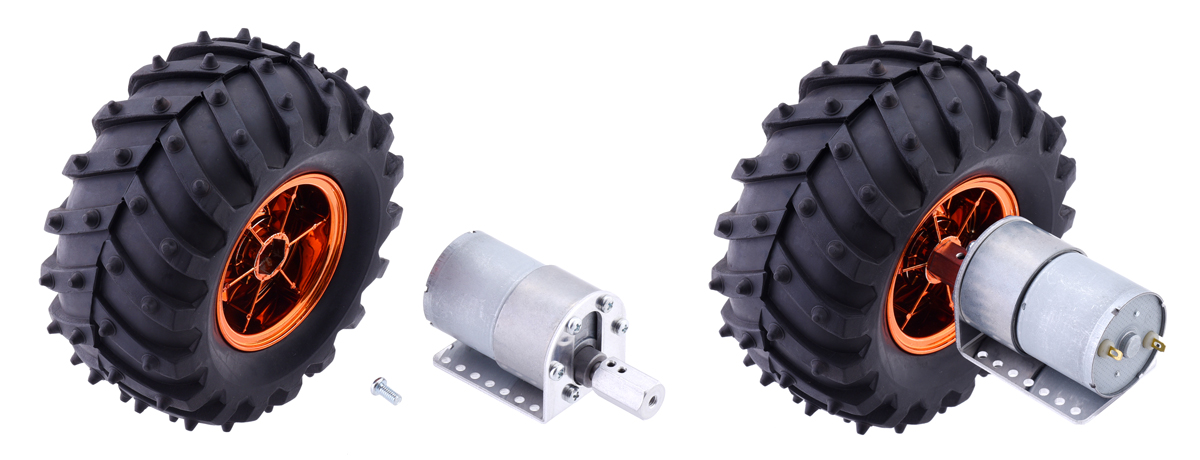 |
12mm Hex Wheel Adapter for 6mm Shaft connecting a Wild Thumper Wheel to a 37D mm Metal Gearmotor. |
|---|
For our full selection of these adapters, see our hex wheel adapter category.
Related products


New motor driver carriers for the BD65496MUV and MAX14870
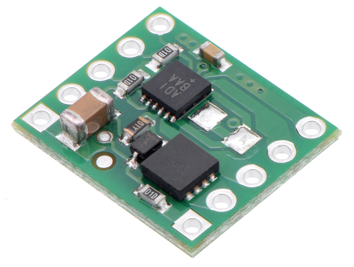 |
We have two exciting new DC motor driver carriers to introduce, one for ROHM’s BD65496MUV and one for Maxim’s MAX14870:
|
|

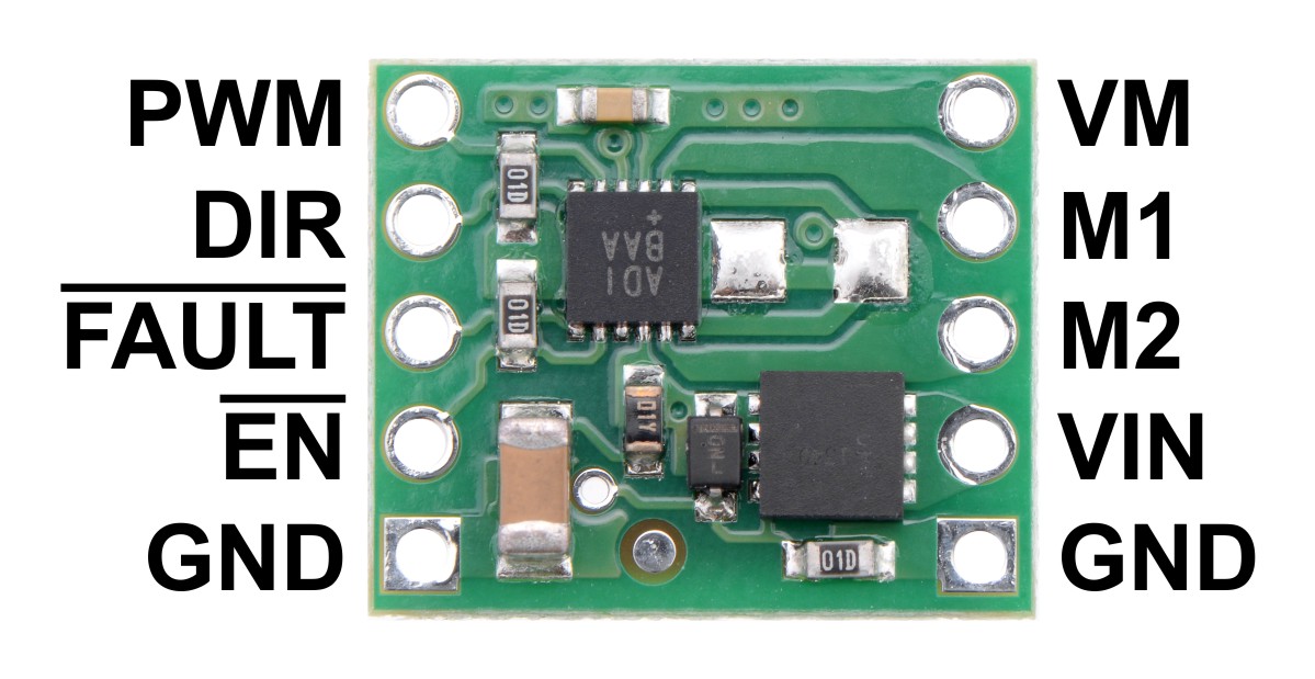
These drivers each offer wide operating voltage ranges, with the BD65496MUV operating from as low as 2 V up to 16 V and the MAX14870 operating from 4.5 V all the way up to 36 V. They can each supply over an amp to a single, bidirectional brushed DC motor. These are the highest-performing integrated motor drivers we know of short of substantially larger units such as the MC33926 and VNH5019. For more information on these drivers, click on the related products below:
Related products


New products: Hakko tools
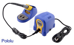
Most electronics projects (and many Pololu products) require soldering. That’s why we’re excited to offer a soldering station and other accessories that we can wholeheartedly recommend! We are now carrying Hakko soldering and desoldering tools and Hakko hand tools (cutters and pliers). We use Hakko tools in our own manufacturing, and we believe they offer a great mix of reliability, performance, and price. Continued…
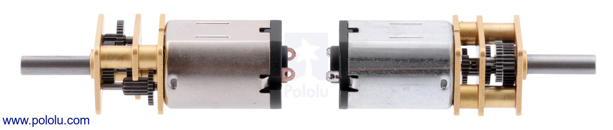
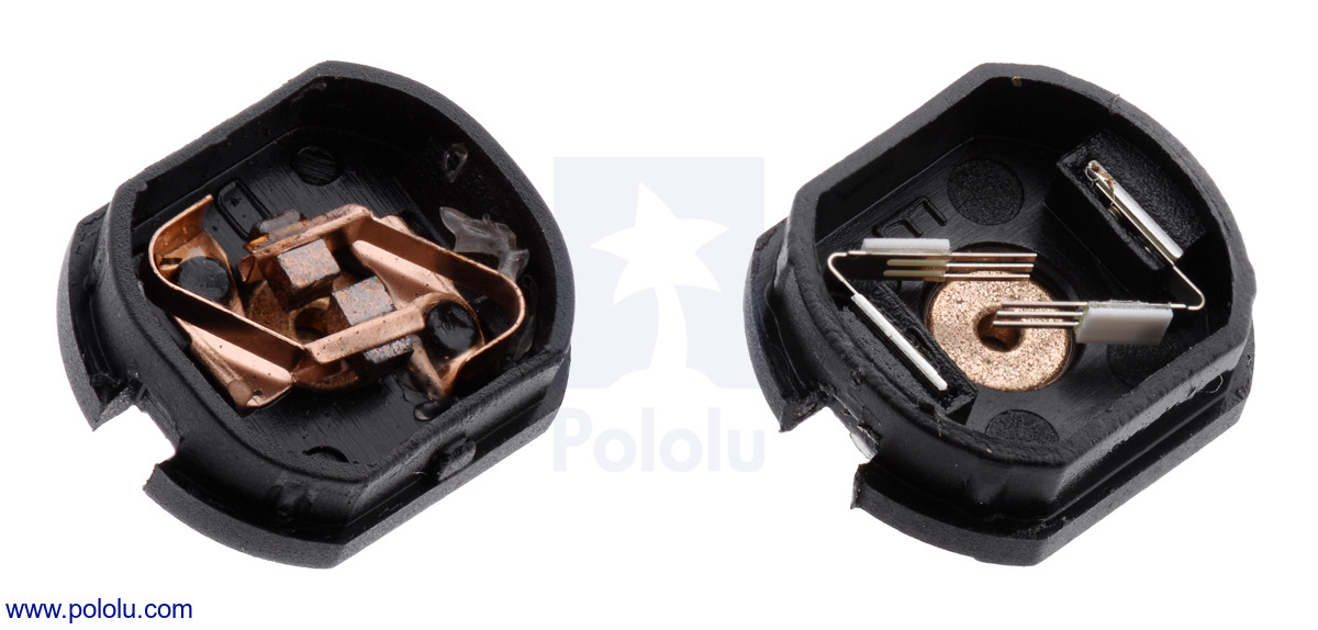
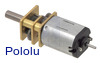
Micro metal gearmotors now available with long-life carbon brushes
We are excited to introduce new versions of our high-power micro metal gearmotors with long-life carbon brushes in place of the standard precious metal brushes:
 |
 |
Micro Metal Gearmotor HPCB long-life carbon brushes (left) next to Micro Metal Gearmotor HP precious metal brushes (right). |
|---|
So far, we only offer these on motors with HP windings, so the brushes being a lot more robust can just move the failure point if you try to push the motors too hard. However, if you use them at around 6 V and keep the continuous load under around 20% of the stall torque, the carbon brushes allow the HPCB motors to last several times longer than HP versions with precious metal brushes.
With the addition of this new HPCB motor variant in ten different gear ratios (10:1 through 1000:1), our selection of popular micro metal gearmotors now spans more than fifty options, giving you control over the motor winding, gearbox, and shaft arrangement:
| Motor Type | Stall Current @ 6 V |
No-Load Speed @ 6 V |
Approximate Stall Torque @ 6 V |
 Single-Shaft (Gearbox Only) |
 Dual-Shaft (Gearbox & Motor) |
|---|---|---|---|---|---|
| high-power, carbon brushes (HPCB) |
1600 mA | 3000 RPM | 4 oz-in | 10:1 HPCB | |
| 1000 RPM | 9 oz-in | 30:1 HPCB | |||
| 625 RPM | 15 oz-in | 50:1 HPCB | |||
| 400 RPM | 22 oz-in | 75:1 HPCB | |||
| 320 RPM | 30 oz-in | 100:1 HPCB | |||
| 200 RPM | 40 oz-in | 150:1 HPCB | |||
| 140 RPM | 50 oz-in | 210:1 HPCB | |||
| 120 RPM | 60 oz-in | 250:1 HPCB | |||
| 100 RPM | 70 oz-in | 298:1 HPCB | |||
| 32 RPM | 125 oz-in | 1000:1 HPCB | |||
| high-power (HP) (same specs as HPCB above) |
1600 mA | 6000 RPM | 2 oz-in | 5:1 HP | |
| 3000 RPM | 4 oz-in | 10:1 HP | 10:1 HP dual-shaft | ||
| 1000 RPM | 9 oz-in | 30:1 HP | 30:1 HP dual-shaft | ||
| 625 RPM | 15 oz-in | 50:1 HP | 50:1 HP dual-shaft | ||
| 400 RPM | 22 oz-in | 75:1 HP | 75:1 HP dual-shaft | ||
| 320 RPM | 30 oz-in | 100:1 HP | 100:1 HP dual-shaft | ||
| 200 RPM | 40 oz-in | 150:1 HP | 150:1 HP dual-shaft | ||
| 140 RPM | 50 oz-in | 210:1 HP | |||
| 120 RPM | 60 oz-in | 250:1 HP | |||
| 100 RPM | 70 oz-in | 298:1 HP | 298:1 HP dual-shaft | ||
| 32 RPM | 125 oz-in | 1000:1 HP | 1000:1 HP dual-shaft | ||
| medium-power (MP) |
700 mA | 2200 RPM | 3 oz-in | 10:1 MP | 10:1 MP dual-shaft |
| 730 RPM | 8 oz-in | 30:1 MP | |||
| 420 RPM | 13 oz-in | 50:1 MP | |||
| 290 RPM | 17 oz-in | 75:1 MP | 75:1 MP dual-shaft | ||
| 220 RPM | 19 oz-in | 100:1 MP | 100:1 MP dual-shaft | ||
| 150 RPM | 24 oz-in | 150:1 MP | |||
| 75 RPM | 46 oz-in | 298:1 MP | |||
| 25 RPM | 80 oz-in | 1000:1 MP | 1000:1 MP dual-shaft | ||
| low-power | 360 mA | 2500 RPM | 1 oz-in | 5:1 | |
| 1300 RPM | 2 oz-in | 10:1 | |||
| 440 RPM | 4 oz-in | 30:1 | 30:1 dual-shaft | ||
| 250 RPM | 7 oz-in | 50:1 | 50:1 dual-shaft | ||
| 170 RPM | 9 oz-in | 75:1 | |||
| 120 RPM | 12 oz-in | 100:1 | 100:1 dual-shaft | ||
| 85 RPM | 17 oz-in | 150:1 | |||
| 60 RPM | 27 oz-in | 210:1 | |||
| 50 RPM | 32 oz-in | 250:1 | |||
| 45 RPM | 40 oz-in | 298:1 | 298:1 dual-shaft | ||
| 14 RPM | 70 oz-in | 1000:1 | 1000:1 dual-shaft |
Related products


New product: 0.1″ low-profile male LCD header
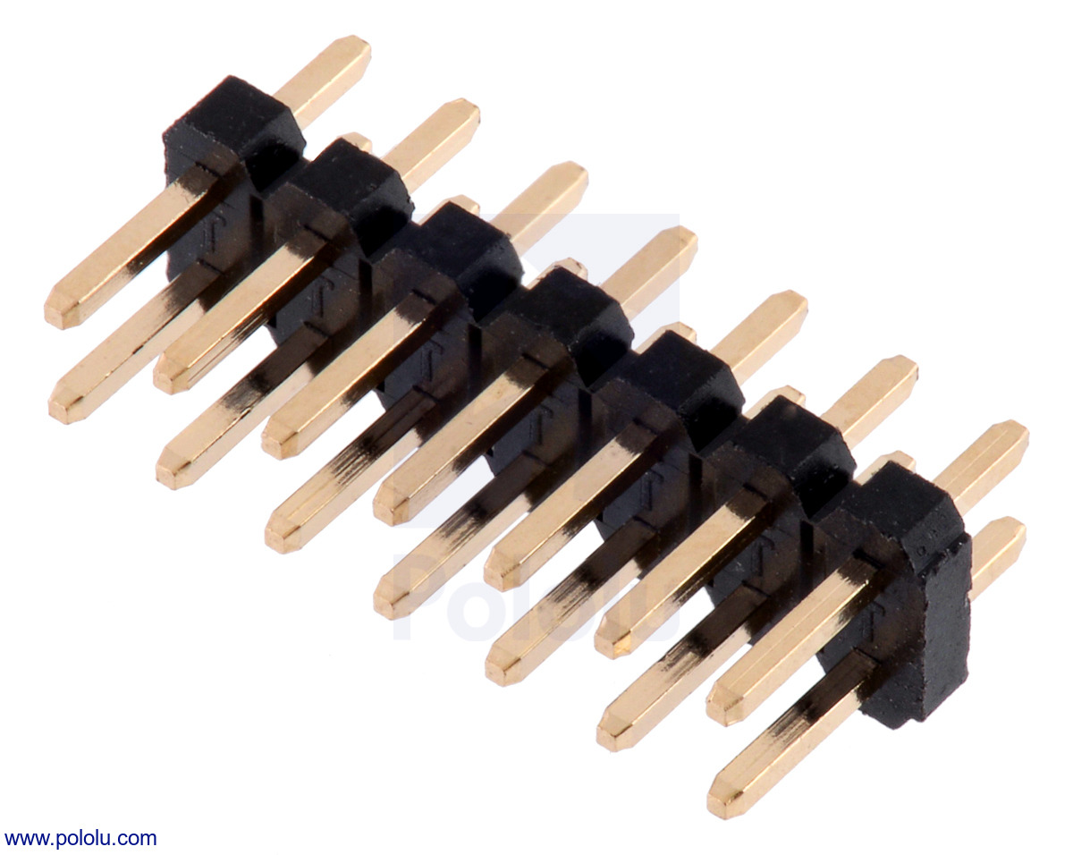 |
We are now selling the low-profile 2×7 male LCD header included with the Zumo 32U4 robot kit.
Related products


New product: Breakout Board for microSD Card with 3.3V Regulator and Level Shifters
 |
In September of last year, we started carrying our Breakout Board for microSD Card, which was the first board that I ever designed and routed here at Pololu. It is a simple breakout board that gives direct access to each contact available on a microSD card socket. However, since microSD cards operate at 3.3 V, it can be tricky interfacing them with a 5 V system. To address this, we made a new version with an integrated 3.3 V regulator and level shifters. Even with the extra components (and mounting holes, which the mechanical engineers at here Pololu are always pushing for), the board is still compact, measuring only 0.94″ × 0.9″, and it breaks out all of the contacts from a microSD card socket necessary to interface with the card through its SPI bus mode interface to a single 1×9 row of 0.1″-spaced pins. This allows easy use with breadboards, perfboards, or 0.1″ connectors.
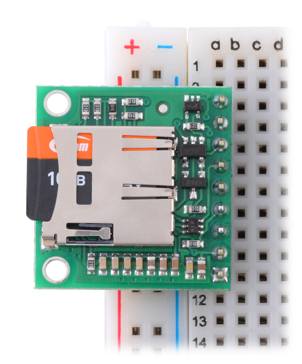 |
You might recognize the circuit from our A-Star 32U4 Prime controllers, which use essentially the same level shifters to interface a microSD card with an Arduino-compatible ATmeg32U4 microcontroller running at 5 V.
For more information about this breakout board, see its product page.
Related products


Home | Forum | Blog | Support | Ordering Information | Lists | Distributors | BIG Order Form | About | Contact
© 2001–2026 Pololu Corporation


