Electronics » Motion Control Modules » Brushed DC Motor Drivers »
BD65496MUV Single Brushed DC Motor Driver Carrier

This compact breakout board for ROHM’s BD65496MUV motor driver offers an operating voltage range of 2 V to 16 V and can deliver a continuous 1.2 A (5 A peak for a few milliseconds) to a single brushed DC motor. The motor driver features variable switching speed, allowing for PWM frequencies up to 500 kHz, two drive mode options, and built-in under-voltage and over-temperature protection; our carrier also adds reverse-voltage protection.

| Description | Specs (14) | Pictures (9) | Resources (6) | FAQs (0) | On the blog (1) | Distributors (37) |
|---|
Overview
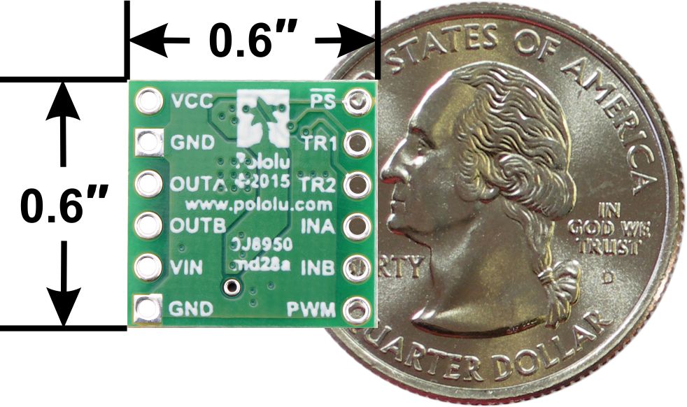 |
BD65496MUV Single Brushed DC Motor Driver Carrier, bottom view with dimensions. |
|---|
The BD65496MUV from ROHM is a tiny H-bridge motor driver IC that can be used for bidirectional control of one brushed DC motor at 2 V to 16 V. It can supply up to about 1.2 A continuously and can tolerate peak currents up to 5 A for a few milliseconds. The BD65496MUV is a great IC, but its small surface-mount package makes it difficult for the typical student or hobbyist to use; our breakout board makes it easy to use with standard solderless breadboards and 0.1″ perfboards. Since this board is a carrier for the BD65496MUV, we recommend careful reading of the BD65496MUV datasheet (481k pdf). The board ships populated with SMD components, including the BD65496MUV and a reverse battery protection circuit.
Features
- Single-channel H-bridge motor driver with shoot-through protection and internal free-wheeling diodes (can drive one DC motor)
- Motor supply voltage: 2 V to 16 V
- Logic supply voltage: 2.5 V to 5.5 V
- Output current: up to 1.2 A continuous (5 A peak for a few milliseconds)
- Two possible interface modes: IN/IN or EN/IN (one pin for speed and another for direction)
- Configurable switching speed allows for PWM frequencies up to 500 kHz
- Under-voltage lockout on the logic supply and protection against over-temperature
- Carrier board adds reverse-voltage protection on the motor supply
- Compact size (0.6″×0.6″)
Included hardware
|
|
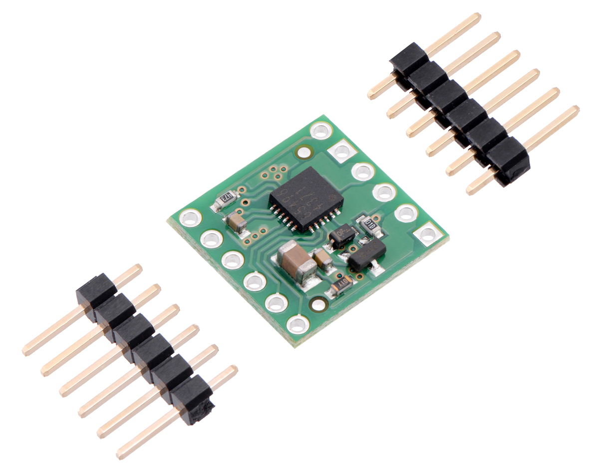

Two 1×6-pin breakaway 0.1″ male headers are included with the BD65496MUV motor driver carrier, which can be soldered in to use the driver with breadboards, perfboards, or 0.1″ female connectors. (The headers might ship as a single 1×12 piece that can be broken in half.) The right picture above shows the two possible board orientations when used with these header pins (parts visible or silkscreen visible). You can also solder your motor leads and other connections directly to the board.
Using the motor driver
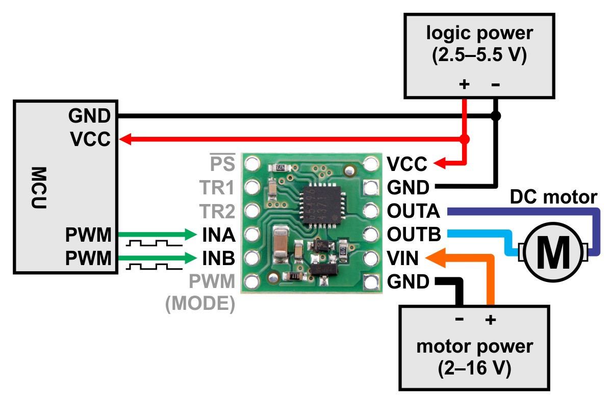 |
Minimal wiring diagram for connecting a microcontroller to a BD65496MUV Single Brushed DC Motor Driver Carrier (default IN/IN mode). |
|---|
Motor and power connections are made on one side of the board and control connections are made on the other. The driver requires an operating voltage between 2 V and 16 V to be supplied to the reverse-protected power input, VIN, and a logic voltage between 2.5 V and 5.5 V to be supplied to the VCC pin; the logic voltage can typically be supplied by or shared with the controlling device.
The BD65496MUV offers two possible control interface modes: IN/IN and EN/IN. The PWM (MODE) pin is used to select the control interface. If the PWM (MODE) pin is left disconnected or driven low, as shown in the minimal wiring diagram above, the selected interface is IN/IN, which generally requires two PWM signals, one for INA and another for INB. If this pin is driven high, as shown in the wiring diagram below, the selected interface is EN/IN, which turns the INB pin into a “motor direction” input and the INA pin into an enable input that can be supplied with a PWM signal to control speed.
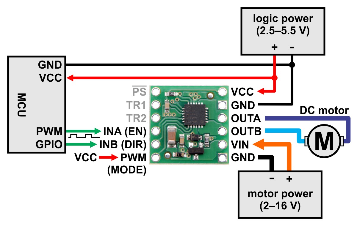 |
Minimal wiring diagram for connecting a microcontroller to a BD65496MUV Single Brushed DC Motor Driver Carrier (EN/IN mode). |
|---|
The PS (power save) pin can be driven low to put the driver into a low-power state and turn off the motor outputs, which is useful if you want to let the motor coast. The PS pin is pulled high through a 47 kΩ pull-up resistor on the carrier board so that the driver is enabled by default; the quiescent current draw of the board will be dominated by the current through this resistor when the pin is driven low to put the driver to sleep. In most applications, this pin can be left disconnected or can serve primarily as a way to enable coasting. For applications where a low-power mode is desirable, the 47 kΩ pull-up resistor can be removed (this resistor is located right next to the PS pin), or the logic voltage (VCC) for the driver can be dynamically supplied by a digital output of your microcontroller.
The following truth table (taken directly from the BD65496MUV datasheet) shows how the driver operates:
 |
Pinout
 |
| PIN | Default State | Description |
|---|---|---|
| VIN | Reverse-protected power supply input; supply this pin with 2 V to 16 V. | |
| VCC | 2.5 V to 5.5 V logic power supply connection. Logic supply current draw is typically only a few milliamps at most, so in many applications this pin can optionally be dynamically powered by a microcontroller digital output. | |
| GND | Ground connection points for the motor and logic supplies. | |
| OUTA | H-bridge output A. | |
| OUTB | H-bridge output B. | |
| PWM (MODE) | LOW | Drive mode selection pin. LOW=IN/IN; HIGH=EN/IN. |
| INA | LOW | Motor control input A (functions like an enable pin in EN/IN mode). |
| INB | LOW | Motor control input B (functions like a direction pin in EN/IN mode). |
| PS | HIGH | Sleep/coast input. Drive low to tri-state the driver outputs and enable power-save mode. |
| TR1 | LOW | Turn-on and turn-off time selection input 1. |
| TR2 | LOW | Turn-on and turn-off time selection input 2. |
All of the driver inputs except PS are internally pulled low through 100 kΩ pull-down resistors. The PS pin is pulled high on the carrier board through a 47 kΩ pull-up resistor that overpowers the driver IC’s internal 300 kΩ pull-down.
The TR1 and TR2 pins control the driver’s turn-on and turn-off time. Both pins are low by default, resulting in a default turn-on time of 150 ns (typical) and a default turn-off time of 50 ns (typical); this allows for PWM frequencies up to 500 kHz. If such a high switching frequency is not required, the TR1 and TR2 inputs can be configured for longer turn-on and turn-off times to help reduce electromagnetic interference (EMI). See the datasheet for more information.
Real-world power dissipation considerations
The BD65496MUV datasheet rates this driver for a maximum continuous current of 1.2 A. In our tests, we found that the chip was able to deliver 1.2 A comfortably over the full operating voltage range, with the driver temperature only approaching the thermal shut down point at the very low end of the motor supply range. At 9 V in, we did not see the driver’s thermal shutdown activate until we pushed the continuous current past 1.5 A for many minutes, but we generally advise against running so close to the limit that the driver overheats. Our tests were conducted at 100% duty cycle with no forced air flow; PWMing the motor will introduce additional heating proportional to the frequency.
This product can get hot enough to burn you long before the chip overheats. Take care when handling this product and other components connected to it.
Schematic
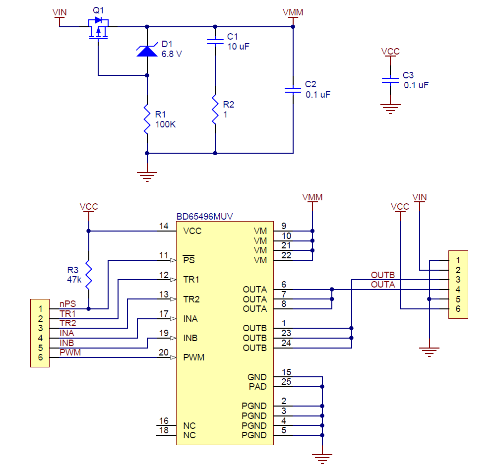 |
BD65496MUV single brushed DC motor driver carrier schematic diagram. |
|---|
This schematic is also available as a downloadable pdf (139k pdf).
Related products


Home | Forum | Blog | Support | Ordering Information | Lists | Distributors | BIG Order Form | About | Contact
© 2001–2026 Pololu Corporation
