Pololu Blog »
New high-current stepper driver carrier with SPI: AMIS-30543
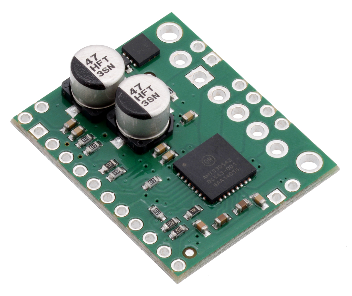 |
This new board is a Pololu carrier for ON Semiconductor’s AMIS-30543 Micro-Stepping Motor Driver, which is a high-performance stepper motor driver with advanced features not found on our other stepper motor driver carriers.
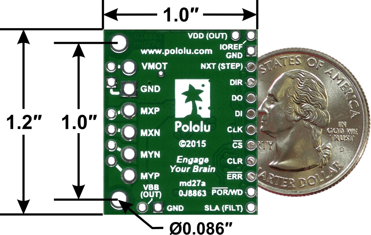 |
AMIS-30543 stepper motor driver carrier, bottom view with dimensions. |
|---|
The Pololu AMIS-30543 Stepper Motor Driver Carrier breaks out all of the important pins of the driver onto breadboard-compatible 0.1"-spaced pins, with optional terminal blocks for the power and motor connections and mounting holes for a more robust setup. Our board supplies reverse protection and all the necessary circuit components for interfacing to a microcontroller.
The AMIS-30543 is rated up to 30 V and 3 A, but (as with other stepper drivers) the current rating is a theoretical maximum assuming excellent cooling. Using our board at room temperature without a heatsink, the chip can practically supply about 1.8 A per coil, more than any of our other stepper motor driver carriers.
The SPI interface of the AMIS-30543 provides many exciting features: it lets you configure microstepping (down to 1/128-step), set the current limit, select voltage slopes, change direction, disable the outputs or put the driver to sleep, monitor the micro-step position and errors, and more. Please note, however, that you cannot step the motor over SPI.
Many of our customers have asked for software current limit control, since it allows better power management. For example, consider that stepper motors counter-intuitively use their maximum current when stopped, even if there is no holding torque required. This wastes a lot of power and generates undesirable heat in the drivers and motors. In a typical application like a 3D printer, where you don’t need much holding torque, you would want to reduce the current limit to a low value during pauses. You might use a higher limit (above the continuous limit) when accelerating and an intermediate value for constant-speed motion. The SPI current limit control on the AMIS-30543 lets you do all of this in your code.
Another advanced feature is the SLA (speed and load angle) output that indicates the level of the back-EMF voltage of the motor. This is an analog signal that can be used for stall detection or closed-loop control of the torque and speed:
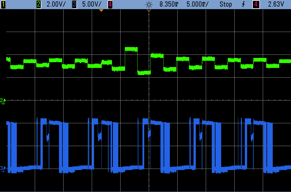 |
AMIS-30543 stepper motor driver SLA output (green) and motor output (blue). |
|---|
It is easy to get started using our Arduino library on GitHub, which provides basic functions for configuring and operating the driver as well as access to many of the advanced features. Please visit the product page for a detailed description, wiring diagrams, the AMIS-30543 datasheet, and more.
Related products

-

More new distributors
- 21 May 2015Core Electronics, in Adamstown, New South Wales, joins five other distributors in Australia and carries a wide variety of electronics parts for the...
-

Memorial Day weekend sale
- 22 May 2015We are having a big Memorial Day sale now through Monday, with discounts on over 600 products when you use the coupon code MEMORIALDAY15. Stock up...
12 comments

I really, really love Pololu products. But I have a small criticism: please, we are in 2015, could you switch to using metric units instead of imperial units? That would really, really be a good thing.
Thank you very much.

We generally prefer metric units, too, but when the standard pin spacing is 0.1", dimensions in inches are generally much nicer. For example, you can immediately tell that a row spacing of 0.7" is breadboard-compatible; can you easily tell if a spacing of 1.778 cm is breadboard compatible?
-Claire

just one question: Studying your third example of the Arduino Library, everyone can see that you are quite well informed about the driver-ic;-)
it would be a great thing if you could provide one more library-example dealing only with some examples of the SLA-output (stall-detection, speed and missing step-control, dealing with the problem of switching to a lower microstepping mode...), because it is hard for a beginner dealing with this topic. of course there is the detailed information from ON Semi, but some examples would be really great.
can you imagine providing such an example file? thanks a lot!
Heinz
The SLA output on the AMIS-30543 is an advanced and complicated feature, so we have no immediate plans to make a beginner example for using it. We appreciate the feedback though, and will keep it in mind.
-Claire

may i ask you, too, how i could start dealing with this feature? i think, there will be more people developing with this new driver, if they see that it is possible using this awsome feature without having an electronics - degree;-). beside the possibility of setting current via SPI, the back-EMF measuring is the other big feature why people will decide to buy this controller, don't you think so?
what i did so far was measuring the voltage of the LSA-pin on an arduino Analog input pin. depending on microstepping mode, and step-speed i get different values, changing not only in speed but significantly in gain.
so far the most significant output with the highest amplitude could be reached with the following settings:
driver set to transparency-mode ON (having the full range of voltage change, not only at the zero-crossings)
driver output current set to 400mA
microstepping mode: 128
step frequency: 50KHz
if i measure on my analog input pin, without any delay in my sketch, and send this to the serial output (also without any delays, set to the highest baud rate of 250000), i get the following values in my serial monitor:
so, as you can see, there is a kind of continuity, but its hard for me to take it as a basis for further enhancements. what dou you think, is it possible, that this values show the real EMF values? somehow i have the impression, that it is more a kind of interference-wave...
unfortunately i have no oszilloscope, so i cannot measure the behavior of the SLA-pin more accurate.
it would be a great help if you could provide a basic example, maybe only for a certain speed nad microstep-setting, just to have a starting point. for me it was a great step to hear about this new feature, which you also advertise as a main feature of the driver, coming to us as "arduino-level" educated consumers. if this feature is not going to be used in a relatively easy way, this new driver would be only half as useful as it could be...
thank you!
I am glad you are interested in our new AMIS driver carrier. However, blog comments are not an appropriate place for this level of technical help.
I noticed that you also posted about this topic on our forum. I recommend continuing the discussion there.
Also, your post was difficult to read with the all your serial monitor outputs, so I removed that portion of your comment. If you have large portions of text like that to share, there are websites that can help with that (e.g. pastebin.com).
-Claire

my name is Giacomo, i'm 19 years old and i'm an Italian maker. I am planning a 3d printer using as electronic Arduino Due + Ramps-FD v1 and stepper motors Nema23 (2.8A, 0.9 °/step) andI would like to use the StepStick AMIS that are the only ones compatible with 2.8A stepper motors (using an adeguate air cooling system). Can i mount the AMIS stepstick on a RAMPS-FD v1 in any way (the carrier is not the same) ?
Thank you very much :D
Giacomo.

StepStick is a brand of stepper motor driver carrier that we do not make or carry. The AMIS-30543 stepper motor driver uses different signal inputs than the A4988 and DRV8825 and will probably not be compatible with shields designed for those stepper motor drivers.
- Grant


The step angle is a property of the physical configuration of the stepper motor and the signaling method the driver uses to step the motor is not dependent on that physical configuration. Because of this, our stepper library and examples deals with movement in steps rather than angles, though you can write code to take an angle and translate it to the appropriate number of steps. So with your 50 step/rev motor and the driver in full step mode, each step is 7.2 degrees.
By the way, I noticed you posted a similar topic on our forum. I have posted this response there as well and if you have additional questions, that is probably a better place to continue this conversation.
-Nathan

How can I use a single arduino uno to control (and calibrate) two of these driver boards (one for each motor) ?
I cannot see how to wire the whole thing...
Cheers
It looks like you asked the same question on our forum. Please see our response and if you need more assistance continue the discussion there.
-Claire
Post a comment


Home | Forum | Blog | Support | Ordering Information | Lists | Distributors | BIG Order Form | About | Contact
© 2001–2026 Pololu Corporation
