Pololu Blog » User Profile: Claire »
Posts by Claire
You are currently viewing a selection of posts from the Pololu Blog. You can also view all the posts.
Popular tags: community projects new products raspberry pi arduino more…
New products: DRV8434A and DRV8434S stepper motor driver carriers
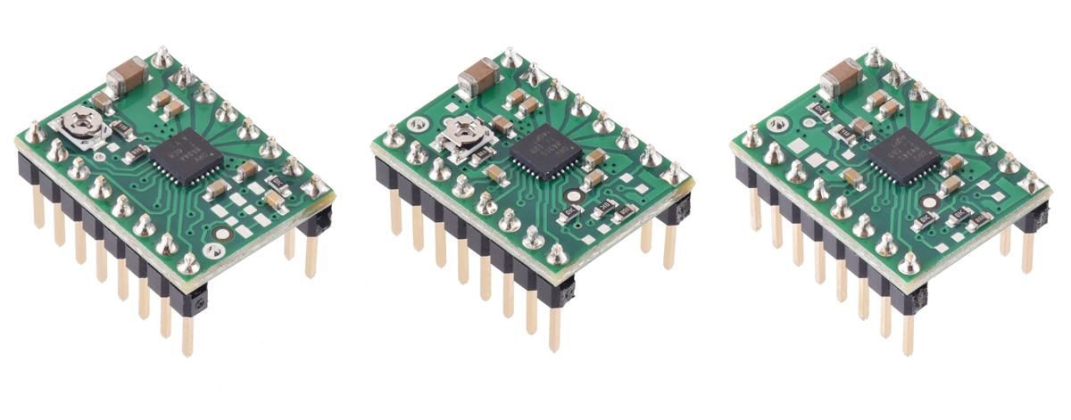 |
Our selection of compact stepper motor driver carriers is expanding with the addition of three new boards based on the DRV8434A and DRV8434S from Texas Instruments. They feature stall detection, adjustable current limiting, over-current and over-temperature protection, and 11 microstep resolutions (down to 1/256-step). They operate from 4.5 V to 48 V and can deliver approximately 1.2 A continuous per phase without a heat sink (up to 2 A peak). The DRV8434A version uses a standard GPIO interface for configuring microstepping and stall detection and a potentiometer for setting the current limit, while the DRV8434S versions use SPI to configure microstepping, stall detection, decay modes, and the effective current limit.
Two DRV8434S carrier versions are available, one with a potentiometer for adjusting the maximum current limit and one with the maximum current limit fixed at 2 A; on both of these, the actual current limit can be scaled down to some percentage of the set maximum through SPI. There are 16 evenly spaced scale settings available, which corresponds to increments of 125 mA on the version with the fixed 2 A maximum. For lower-current applications that would benefit from finer current limit resolution, we recommend the version with the potentiometer. For example, if you set the maximum to 500 mA with the pot, you can then use SPI to scale the current limit down from there in increments of 31 mA.
All carriers are available with and without header pins soldered. The following table compares the key differences among the three versions:
 DRV8434A |
 DRV8434S (Potentiometer for Max. Current Limit) |
 DRV8434S (2A Max. Current Limit) |
|
|---|---|---|---|
| Configuration: | I/O pins | SPI | |
| Control interface: | STEP and DIR pins | STEP and DIR pins or SPI | |
| Stall detection: | through GPIO | through SPI | |
| Current limit: | Potentiometer setting (0–2 A) |
Potentiometer setting for max. (0–2 A), scaled with SPI setting (%) |
2 A fixed max., scaled with SPI setting (%) |
| Decay modes available: | 1 | 8 | |
| Available versions: | |||
One of the most exciting features of these new chips is their integrated stall detection. We make carriers for a few other stepper motor drivers that provide back EMF outputs, such as the AMIS-30543 and High-Power Stepper Motor Driver 36v4, but processing those signals for stall detection is complex. On the DRV8434A and DRV8434S, the back EMF processing is integrated into the chip and a learning mode is provided to make stall detection simpler and more accessible. Even so, these drivers’ stall detection functionality might not work well in every application, and we have some notes on the product pages with tips on getting it to work (such as using hardware PWM to generate a steady step signal).
|
|
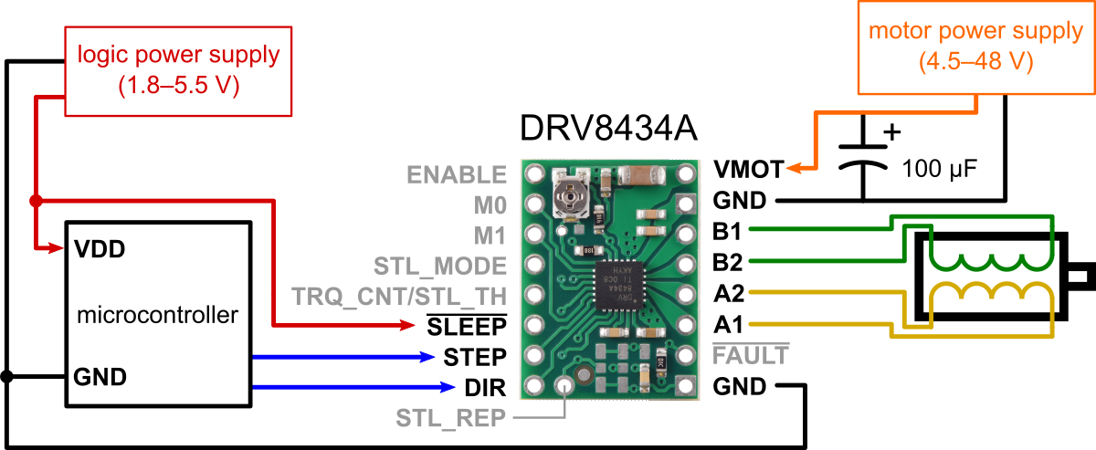
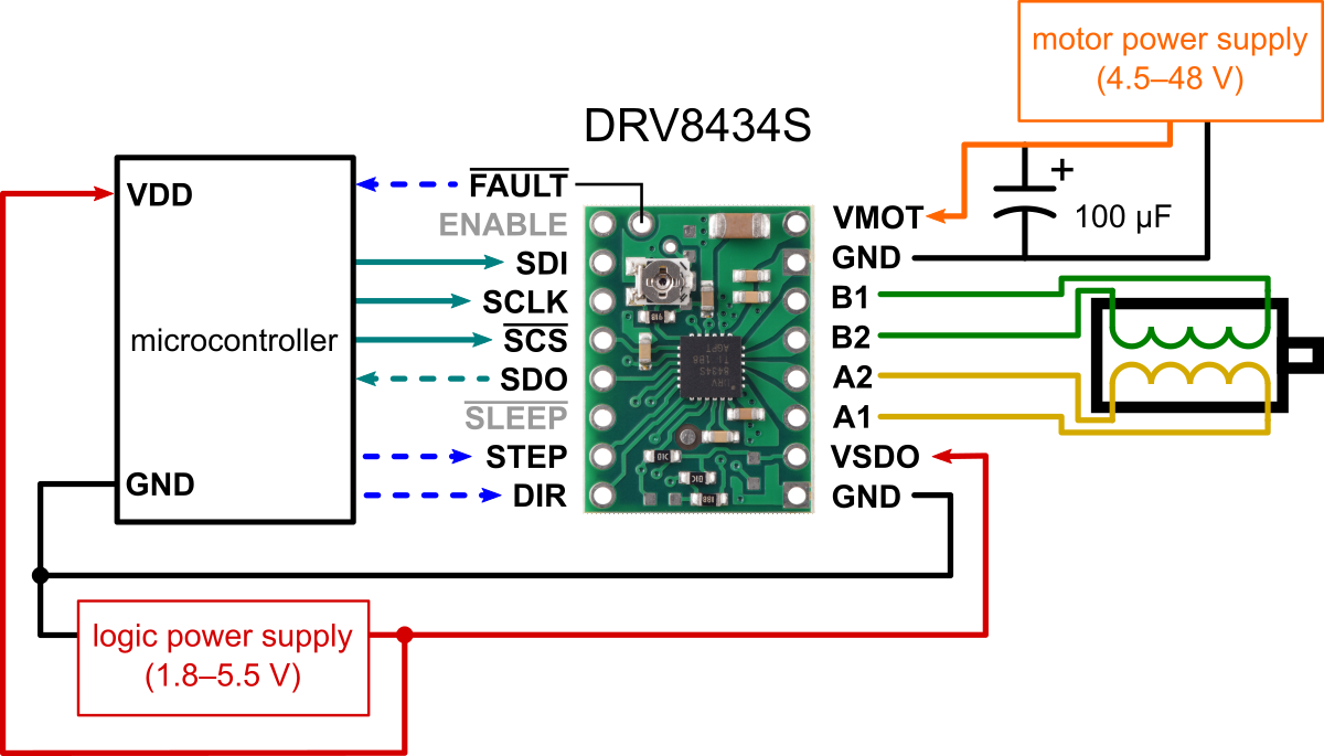
The DRV8434A carrier was designed to be as similar to our popular A4988 and DRV8825 stepper motor driver carriers as possible, and it can be used as a drop-in replacement for these in many applications because it shares the same size, pinout, and general control interface. The DRV8434A always operates with a decay mode that TI calls “smart tune ripple control”, which tries to minimize the ripple current through the motor coils for smoother stepping and reduced audible noise in many cases. If additional flexibility is required, the DRV8434S offers a choice of eight decay modes, configurable through SPI; these include slow, mixed, and fast decay as well as the more advanced smart tune dynamic decay and smart tune ripple control modes.
TI also makes a DRV8434 (with no letter A or S at the end) in the same family of drivers. This version doesn’t have the stall detection feature or SPI, but it gives you the same choice of eight decay modes that the DRV8434S does. Why don’t we have a carrier board for the DRV8434 then? Well, we do have the boards, but with the extra long lead times right now, it could still be a while before we have the chips. (These are parts we ordered in June 2021, so more than 16 months ago now!)
 |
DRV8434/DRV8434A Stepper Motor Driver Carrier, bottom view with dimensions. |
|---|
Our DRV8434A carrier’s printed circuit board is designed to work with the DRV8434 too, and that’s why some of the pins are labeled with two names on the silkscreen. So, for those of you interested in a DRV8434 carrier, those will be coming some day!
Related products


New product: 5V Step-Up/Step-Down Voltage Regulator S13V30F5
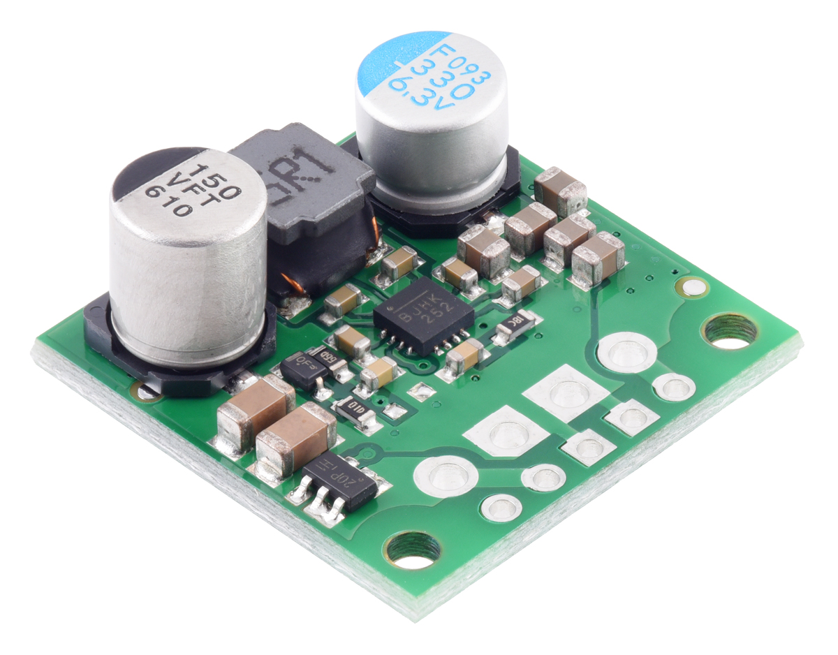 |
I started routing the PCB for the S13V30F5 5V step-up/step-down voltage regulator in January of 2020, and we were in the middle of testing the assembled prototypes when the pandemic shutdowns hit. Like lots of other things in 2020, the project got put on hold because appropriate testing requires a decent amount of equipment and is not the easiest thing to do remotely. That only makes it more exciting to announce that the S13V30F5, our most powerful step-up/step-down regulator, is now available! It operates from 2.8 V to 22 V and steps that voltage up or down as necessary to produce a fixed 5V output with typical efficiencies of 85% to 95%. As shown in the graph below, it can deliver around 3A continuously when the input is near 5V.
 |
This new regulator measures just 0.9″ × 0.9″. That is almost half the size of our previously highest-power step-up/step-down units, the S18V20Fx family, which we have recently started rationing due to impacts from the global semiconductor shortages.
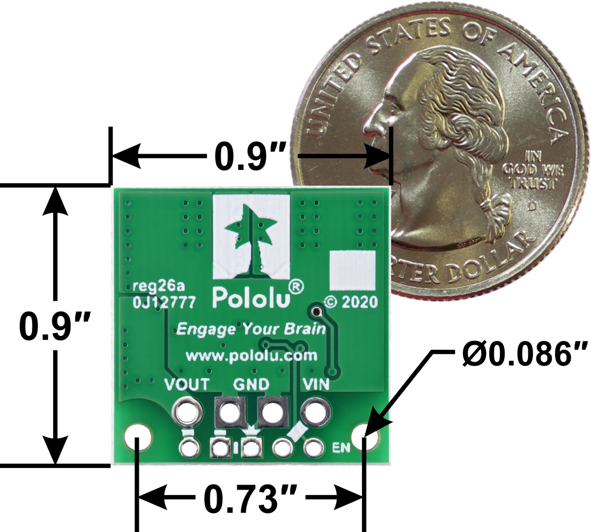 |
5V Step-Up/Step-Down Voltage Regulator S13V30F5, bottom view with dimensions. |
|---|
To help celebrate finally releasing the S13V30F5, we are offering an extra introductory special discount. The first hundred customers to use coupon code S13V30F5INTRO can get up to five units for just $9.95 each!

Related products

Laser-cut teapot coasters
This past weekend my mom hosted a tea-themed baby shower for me, and after looking around and not finding any party favors I liked, I decided to make my own custom laser-cut teapot-shaped coasters for it. To get started, I searched some free vector file sites for a vector file of a teapot that I liked and could easily prepare for laser-cutting with CorelDRAW. I chose this one designed by Freepik. Once loaded into the software, I resized the teapot and added text. I personally really like cork as a coaster material since it keeps the cup from slipping and absorbs moisture well, so I also picked up some 1/8″ cork place mats from IKEA.
Evidently, cork is not a material we are asked to laser-engrave very often, so I had to do some experimenting with the engraving settings before cutting out prototypes.
|
|

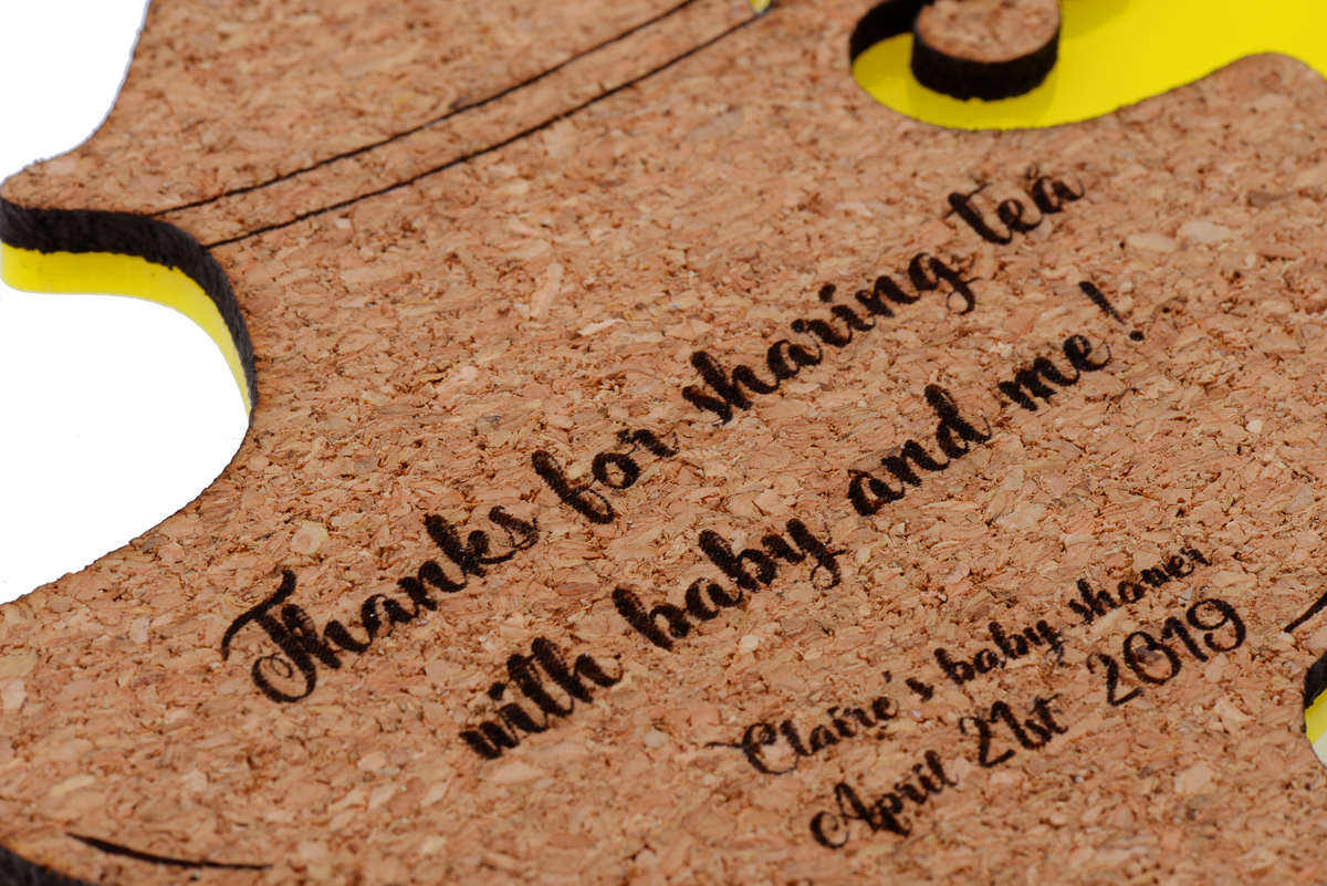
I generally liked the look of the first draft, but realized that at 4 inches total width it was too small to be practical (and readable). In addition, the handle of the teapot was fairly fragile since the cork was only an eighth of an inch thick. Below you can see the first draft of the cork teapot in the upper left. It is missing the small circular embellishment at the base of the handle.
 |
Comparison of different test coaster sizes. |
|---|
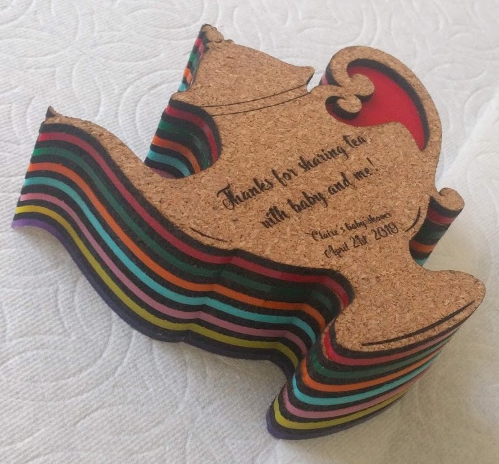
For the second draft, I increased the size to about 5.5 inches, edited my file to thicken the areas of the teapot where the handle connects to the base, and started playing with different acrylic backings to make the coasters more durable and colorful. I tried a version with an outline around the cork teapot and one that fit directly beneath the cork.
|
|
|


In the end, I went with the sleeker acrylic with no outline, though most of the others I consulted here preferred the mirrored outline shown on the left above (despite my insistence that it looked like a magic lamp). I cut out a variety of colors and glued them to the back of the cork with rubber cement.
|
|
|


All in all I think they came out well (though I could have made the attachment for the small circle at the bottom of the handle even thicker), and they were definitely a big hit at the party!
If you want to try your own laser cutting project, submit a quote request here!
Related products

Video: Raspberry Pi robot with the Romi chassis
A few weeks ago I posted a tutorial on building a Raspberry Pi robot with the Romi 32U4 Control Board and Romi Chassis. Now we have a short video of the robot in action! For the full tutorial, see my earlier post.
Related products


Building a Raspberry Pi robot with the Romi chassis
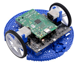
This tutorial shows how to build a basic Raspberry Pi robot with the Romi chassis and the Romi 32U4 Control Board, our Arduino-compatible microcontroller board designed specifically for the Romi. With this setup, the powerful Raspberry Pi can take care of high-level tasks like motion planning, video processing, and network communication, while the Romi 32U4 Control Board takes care of low-level tasks that the Pi is incapable of, such as motor control and sensing. Continued…
“Knock knock unlock” puzzle box
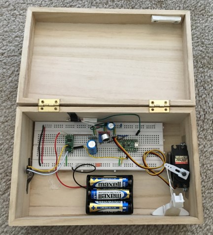 |
With the holiday season upon us, many are on the hunt for interesting projects that we can give as gifts. This year, why not make your project about unveiling your gift? You would still have to get an actual gift to put inside the box, but you’d win major style points. Forum member Bob Day’s knock knock unlock puzzle box has no visible way of opening it, but given the right combination of knocks will unlatch itself with the help of a servo and several other electronic components inside. The puzzle box is controlled by an A-Star Micro, which is powered by our S7V8F5 voltage regulator and a mini LV pushbutton power switch. The power switch is turned on by a mercury tilt switch and turned off by the A-Star if no knocks are received for about 30 seconds. This power switch circuit allows power to be completely turned off, which should extend the battery life tremendously over just leaving the A-Star on. (For advanced microcontroller programmers, another option would be to put the A-Star into a low-power mode.) A list of the parts and connections used and some example code for the box are given on Bob’s blog.
 |
“Knock Knock Unlock” Puzzle Box outside view. |
|---|
If you found this project interesting, you might also like a similar GPS puzzle box, also created by Bob, that we featured on our blog last year. That box unlocked when brought to a specific location and included a simpler toggle switch for power and an LCD screen.
Related products


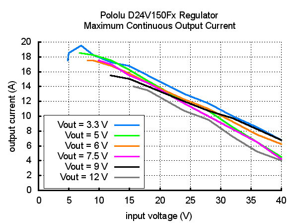
New D24V150Fx 15A step-down voltage regulator family — our highest-power regulators yet!
 |
I am excited to announce that we just released our highest power regulators ever. The new D24V150Fx family of step-down regulators includes units with 3.3 V, 5 V, 6 V, 7.5 V, 9 V, and 12 V outputs and can output currents of around 15 A! With all of the output voltages available, the D24V150Fx family of regulators is great for a variety power-hungry projects like running servos or our metal gearmotors and supplying large LED displays.
|
|

The maximum continuous output currents for all the members of the D24V150Fx family are shown in the graph below. You can see that the available output current is generally a little higher for the lower-voltage versions than it is for the higher-voltage versions, and it decreases as the input voltage increases.
 |
These regulators accept input voltages up to 40 V and have typical efficiencies between 80% and 95%. Integrated reverse-voltage protection, over-current protection, over-temperature shutoff, undervoltage lockout, and soft-start features make these regulators robust, and a power good output can be used to monitor the output voltage.
See the product pages for any of the D24V150Fx regulators for more information on these new regulators, or visit our voltage regulator category to see all of our regulator options.
Related products


Remote control food
With Halloween on its way, and trick-or-treating eminent, you might be asking yourself if there are any alternative uses for the mountain of candy bars your kids will soon be bringing home. Well, customer Mike Kohn, whose projects we previously blogged about, has a solution for giving new life to not just candy, but all sorts of unwanted food items: remote controlled food!
For this project, Mike ditched plastic and aluminum and tried out a sampling of more savory chassis materials like candy bars, a carrot, a bell pepper, a grapefruit, and a chicken sausage. The candy bars, carrot, and sausage were used for four-wheeled differential drive cars and the pepper and grapefruit were used for boats. All the vehicles were actuated by a pair of micro metal gearmotors and the cars also used our 32mm wheels. Below is a picture of one car made with a 3 Musketeers bar.
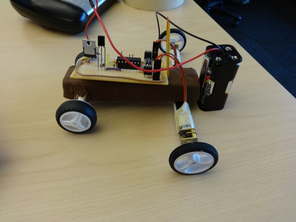 |
Mike also wrote his own firmware for decoding the IR signals from a Syma S107 controller. You can find out which foods made the best chassis and plenty more information about the vehicles, including a parts list, schematic, and several other videos, on Mike’s website.
Related products


Video: Smart lane changing Zumo robot
Forum member WaterBoy23 recently shared his robot which expanded upon the line following capabilities of our Zumo Robot for Arduino by adding in lane changing capabilities. The robot changes lanes when it detects a vehicle ahead of it, and is programmed to either pass the vehicle or return quickly to its original lane if it detects oncoming traffic. His robot uses two Arduino Uno boards, one for following the line and the other for reading ultrasonic position sensors. More information about the robot can be found in WaterBoy23’s post on our forum.
Related products

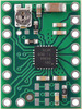
New product: DRV8880 Stepper Motor Driver Carrier
 |
I’d like to introduce our latest addition to the Pololu stepper motor driver carrier family, the DRV8880 Stepper Motor Driver Carrier. This carrier for the Texas Instruments DRV8880 driver has the same form factor and basic layout as our A4988 carrier, which makes it a drop-in replacement in many systems. It also has a lot of the same features, like potentiometer adjustable current control and microstepping down to 1/16-step. In addition, the DRV8880 has many new features like inputs for dynamically scaling the current limit to 25%, 50%, 75%, or 100% of the limit set by the potentiometer, nine decay mode combinations, and autotune (insert Daft Punk joke here), which automatically selects the decay mode each PWM cycle for optimal current regulation performance.
The DRV8880 carrier has a maximum current of 1.6 A, and in our tests it could handle about 1 A per phase continuously. It has a 6.5 V to 45 V input voltage range, which is the widest of any of our stepper motor drivers, and it supports both 3.3 V and 5 V logic. For more information about our DRV8880 stepper motor driver carrier, please see its product page.
Related products


Home | Forum | Blog | Support | Ordering Information | Lists | Distributors | BIG Order Form | About | Contact
© 2001–2026 Pololu Corporation


