Pololu Blog »
Building a Raspberry Pi robot with the Romi chassis
This tutorial shows how to build a basic Raspberry Pi robot with the Romi chassis and the Romi 32U4 Control Board, our Arduino-compatible microcontroller board designed specifically for the Romi. With this setup, the powerful Raspberry Pi can take care of high-level tasks like motion planning, video processing, and network communication, while the Romi 32U4 Control Board takes care of low-level tasks that the Pi is incapable of, such as motor control and sensing.
As long as you have basic soldering skills, assembling the parts is straightforward, but this is not a beginner project: it is intended for people who are comfortable programming both the Raspberry Pi and Arduino-compatible controllers. The Romi 32U4 Control Board can also be used by itself (with no Pi) as a robot controller for the Romi Chassis, so you might consider starting there if you are not ready to work with all of these parts at the same time.
Note: this is based on an earlier project from our blog that used the A-Star Robot Controller.
Here are all the parts you will need; they all come in just three kits plus your Raspberry Pi!
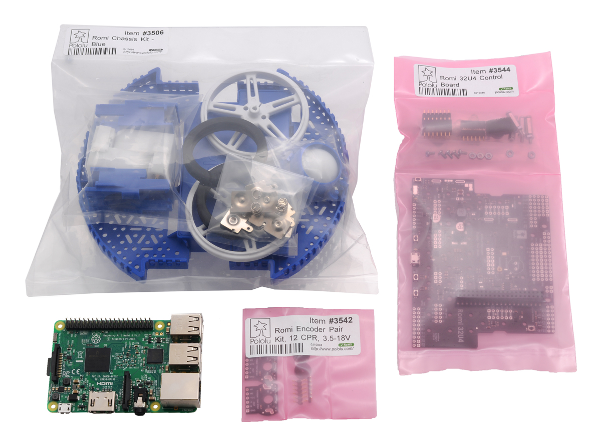 |
Parts needed for a Romi Raspberry Pi robot in packaging. |
|---|
Open up the bags and check that you have all of the pictured parts. (Note that both the chassis and control board kits come with battery contacts, so you will end up with four extra.)
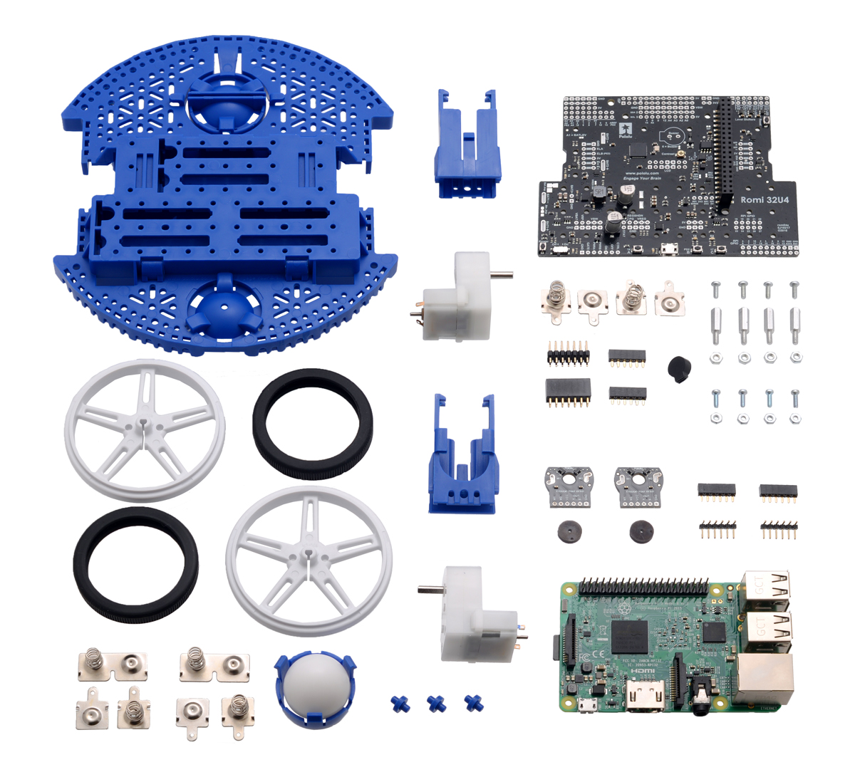 |
Parts needed for a Romi Raspberry Pi robot. |
|---|
Mechanical components
- Romi Chassis Kit – Blue (or other color)
Electronics
- Romi 32U4 Control Board
- Romi Encoder Pair Kit, 12 CPR, 3.5-18V
- Raspberry Pi (such as the Raspberry Pi 3 Model B, Raspberry Pi 1 Model A+, or Raspberry Pi Zero W)
- A microSD card for your Linux installation
- Optional 8×2 character LCD
To mount the Raspberry Pi on top of your controller, you will have to remove the LCD (or possibly build an extension cable), but you probably won’t need it anyway. I did find it useful for initial debugging, but it’s definitely an optional component.
Miscellaneous items that you probably have already
To assemble the Romi 32U4 Control Board, you will need a soldering iron and solder and to program it you will need a USB micro-B cable. You will also need a small screwdriver, six AA batteries, and a battery charger.
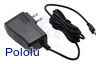
For the initial setup of the Raspberry Pi, you will need a way to power it: Usually powering it from a computer’s USB port will work, but if you have trouble or want to connect a lot of peripherals, I recommend a high-current USB adapter that can do more than 2 A, such as this one. You will also need a keyboard and an HDMI connection to a display. If you want to use a Pi Zero, you will probably also need a USB OTG cable and an HDMI to mini HDMI adapter.
Once you have all your parts, here is how to put them together:
Part 1: Set up the Raspberry Pi
You will need a working Linux distribution (such as Raspbian “Jessie”) on your Raspberry Pi as well as the ability to log in remotely over Wi-Fi, install software, and configure the system. At times you might find it easier to work directly with the Raspberry Pi using a mouse and keyboard, but it is not practical to use the fully assembled robot platform while those are connected. If you are just getting started with the Raspberry Pi, there are hundreds of tutorials available online, but here are links to a few useful resources:
- Raspbian downloads and installation guide
- SD Association’s SD Card Formatter
- Automatically connect a Raspberry Pi to a Wi-Fi network
With the Raspberry Pi 3 or Zero W, Wi-Fi is built-in, and you should not have to do anything to configure it other than selecting a Wi-Fi network. Otherwise, you’ll need a Wi-Fi dongle. If you are using an Edimax or similar Wi-Fi adapter with the 8192cu module, you will notice frustrating delays or dropped connections unless you disable power management. Create a module configuration file:
sudo nano /etc/modprobe.d/8192cu.conf
and add the following lines:
# Disable power management
options 8192cu rtw_power_mgnt=0 rtw_enusbss=0
After setting up Wi-Fi, enable I²C on your Raspberry Pi by running
sudo raspi-config
and selecting the option within the “Advanced” or “Interfacing Options” menu. By default, I²C runs at 100 kHz, but you can safely increase that rate to 400 kHz and get a much faster communications channel between the boards. To increase the speed, edit the configuration file:
sudo nano /boot/config.txt
At the end, add the line:
dtparam=i2c_arm_baudrate=400000
Note that the Raspberry Pi 3 performs frequency scaling (reducing the speed of the processor when there are no intensive computations running) that affects the I²C clock, so even when you increase the frequency to 400 kHz, it will not always run that fast. In our tests it usually ran at half of the specified speed, only jumping up to the full speed occasionally or when under significant CPU load.
If you want to log in as a user other than the default pi, give yourself access to the I²C devices with this command, replacing <user> with your username:
sudo usermod -a -G i2c,dialout <user>
One further configuration step that will come in handy is to allow your user to safely shut down or reboot the Pi without typing a password. On Raspbian Jessie, the user pi can already do this. To make this possible for another user, run visudo and add the following lines at the end, again replacing <user> with your username:
<user> ALL = (root) NOPASSWD: /sbin/halt
<user> ALL = (root) NOPASSWD: /sbin/shutdown
<user> ALL = (root) NOPASSWD: /sbin/reboot
Try it out now with sudo reboot. After the reboot you should see the device /dev/i2c-1 on your Raspberry Pi, indicating that I²C is available. Then shut down the Pi and remove the USB cable before going on to the next step.
halt) before removing power to the Raspberry Pi. As with a normal computer, if you remove power while the Raspberry Pi is running, its filesystem could possibly become corrupted.Part 2: Try out your Romi 32U4 Control Board and test the I²C bridge
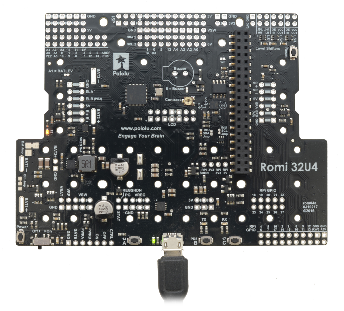 |
I recommend reading through the Romi 32U4 Control Board User’s Guide, particularly the sections on getting started and using the Romi Arduino library. Before putting your control board on the Romi chassis or connecting any other components to it, make sure you can successfully use the Arduino IDE to load the “BlinkLEDs” example from the Romi library.
Next, install the Pololu Raspberry Pi I2C Slave Arduino library. Assuming you are using version 1.6.2 or later of the Arduino software (IDE), you can use the Library Manager to install this library:
- In the Arduino IDE, open the “Sketch” menu, select “Include Library”, then “Manage Libraries…”.
- Search for “Pololu RPi Slave”.
- Click the “Pololu Raspberry Pi I2C Slave Arduino library” entry in the list.
- Click “Install”.
If this does not work, you can manually install the library:
- Download the latest release archive from GitHub and decompress it.
- Rename the folder “pololu-rpi-slave-arduino-library” to “PololuRPiSlave”.
- Move the “PololuRPiSlave” folder into the “libraries” directory inside your Arduino sketchbook directory. You can view your sketchbook location by opening the “File” menu and selecting “Preferences” in the Arduino IDE. If there is not already a “libraries” folder in that location, you should make the folder yourself.
- After installing the library, restart the Arduino IDE.
From the examples menu under PololuRPiSlave, select RomiRPiSlaveDemo, and load this example onto your control board. It is now ready to receive I²C commands from a Raspberry Pi.
At this point you will need to temporarily connect the Raspberry Pi to the Romi 32U4 Control Board. You don’t have to screw them all the way in, but install standoffs in at least a couple of the locations provided to prevent components from touching. (If you are using the Zero, you probably don’t need them at this point.)
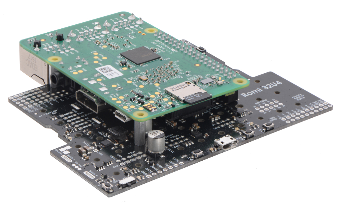 |
The Romi 32U4 Control Board is configured to power the Raspberry Pi from its 5 V supply by default. This means that if you plug a power source into the control board’s USB port, you will turn on both boards. Do that now so you can install the Raspberry Pi software.
To run our Raspberry Pi example code, you should make sure Python 3 and a couple of required libraries are installed. Install them with:
sudo apt-get install python3 python3-flask python3-smbus
Next, download the pololu-rpi-slave-arduino-library code from our GitHub repository. You can do this a number of ways, but if you are unfamiliar with Git, the simplest is to do the following, replacing <version> with the version of the library that you installed for your Arduino IDE (e.g. “2.0.0”).
wget https://github.com/pololu/pololu-rpi-slave-arduino-library/archive/<version>.tar.gz
tar -xzf <version>.tar.gz
mv pololu-rpi-slave-arduino-library-master pololu-rpi-slave-arduino-library
In the folder pololu-rpi-slave-arduino-library/pi is some example Python code for controlling the Romi 32U4 Control Board. Since you loaded RomiRPiSlaveDemo earlier, the Romi 32U4 Control Board should be ready to respond to these commands. Try running
python3 pololu-rpi-slave-arduino-library/pi/blink.py
If everything goes well, you should see the LEDs on the Romi 32U4 Control Board flash a sequential pattern.
Part 3: Assemble the robot
Once you have gotten the control board and Raspberry Pi talking, disconnect the USB cable, take the Raspberry Pi off the control board, and remove the standoffs. Then solder the buzzer and encoder headers to the control board. I also chose to solder in the female LCD connector. You won’t need the LCD connector when using the control board with a Raspberry Pi, but if you think you might want it later, now is a good time to put it in as well. See the Assembling the Romi 32U4 Control Board section of the Romi 32U4 Control Board User’s Guide for details.
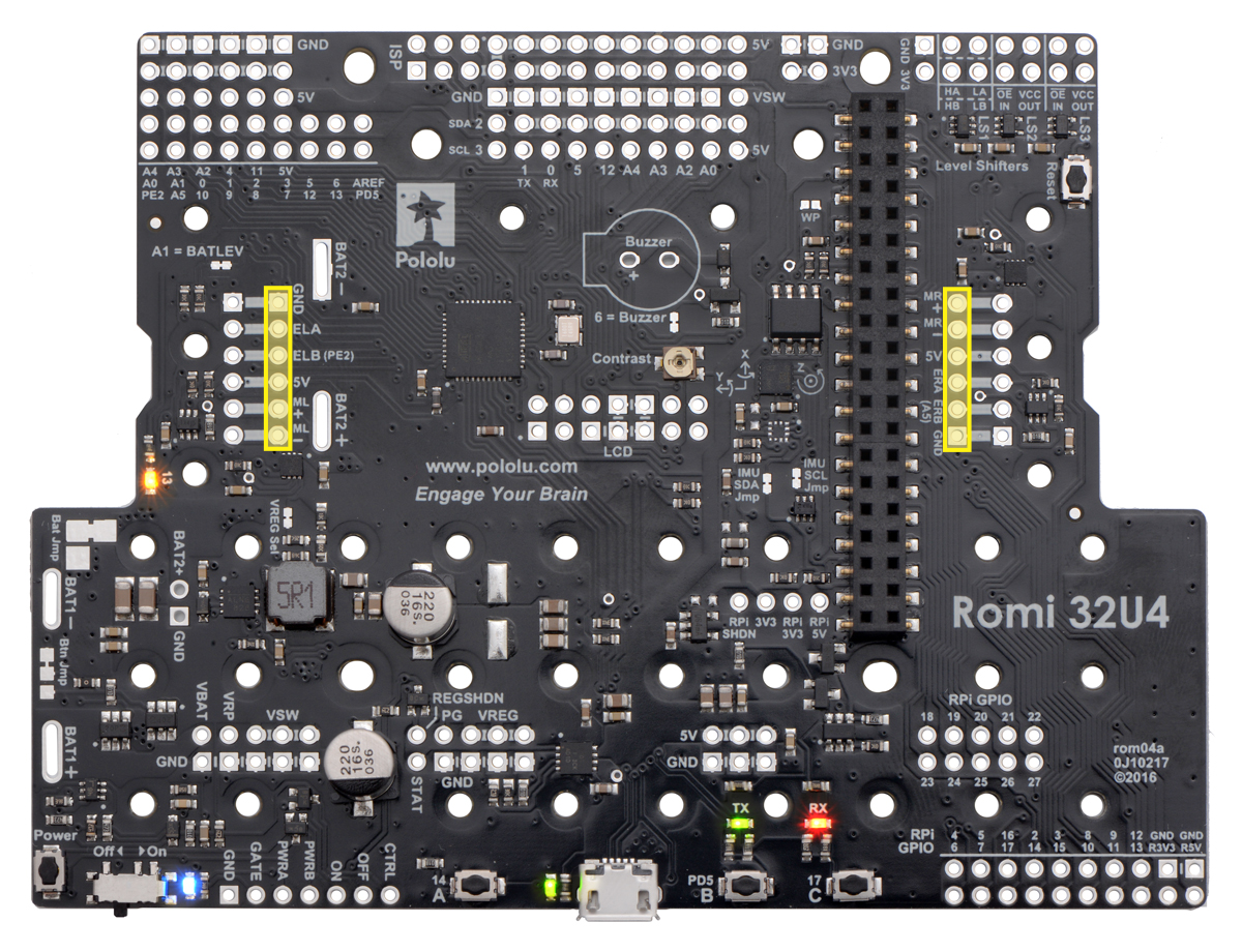 |
Recommended encoder header holes for use with Raspberry Pi. |
|---|
There are two sets of holes for the female encoder headers on the Romi 32U4 Control Board. I recommend soldering the female headers into the set of holes closer to the middle of the board since it makes it easier to plug in the HDMI connector for a monitor while your Raspberry Pi is mounted on the control board. Even though you will usually be controlling the Raspberry Pi remotely, you will likely find it useful at some point to connect directly to the PI.
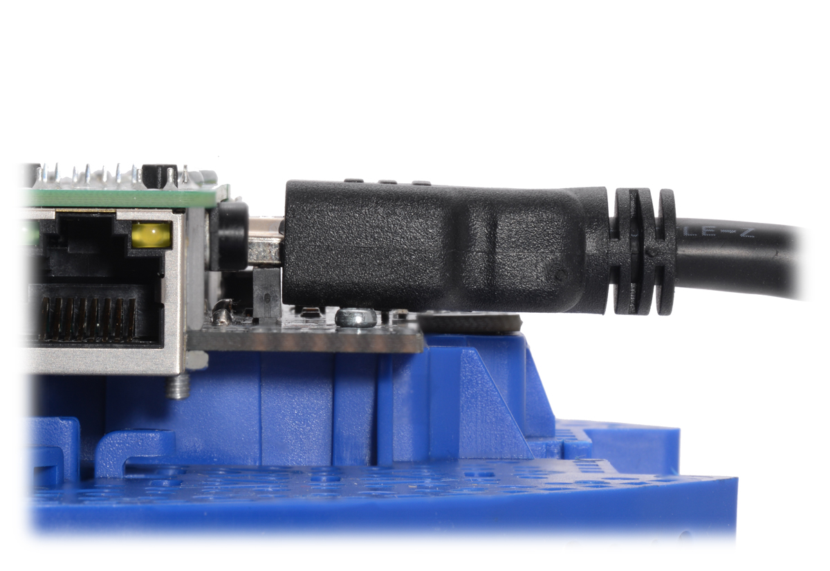
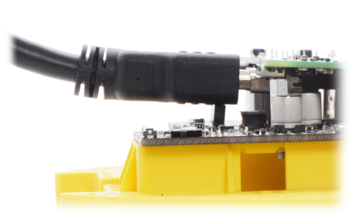
When the header is soldered into the inside holes, it is generally possible for only the metal portion of the HDMI connector to rest on top of the female encoder headers, and there is just enough room for that. With the header in the outside position, the plastic surrounding the connector also rests on the header, so the Raspberry Pi must tilt. The pictures below demonstrate how an HDMI cable fits with the encoder headers soldered in the two different positions. The control board on the blue chassis has the headers soldered into the recommended holes and the ones on the yellow chassis are soldered in the outside set of holes.
|
|
Tip: When soldering the buzzer and headers to the control board I found it easiest to tape each component in place, solder just one pin, check the alignment, and then solder the rest of its pins.
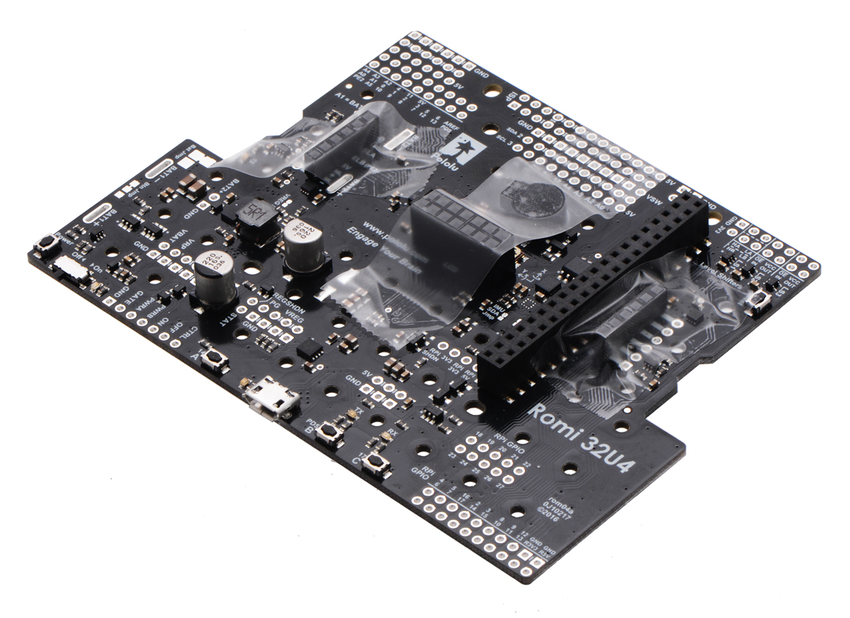 |
To begin assembling the chassis, insert the two double battery contacts into the underside of the battery holder, as shown below:
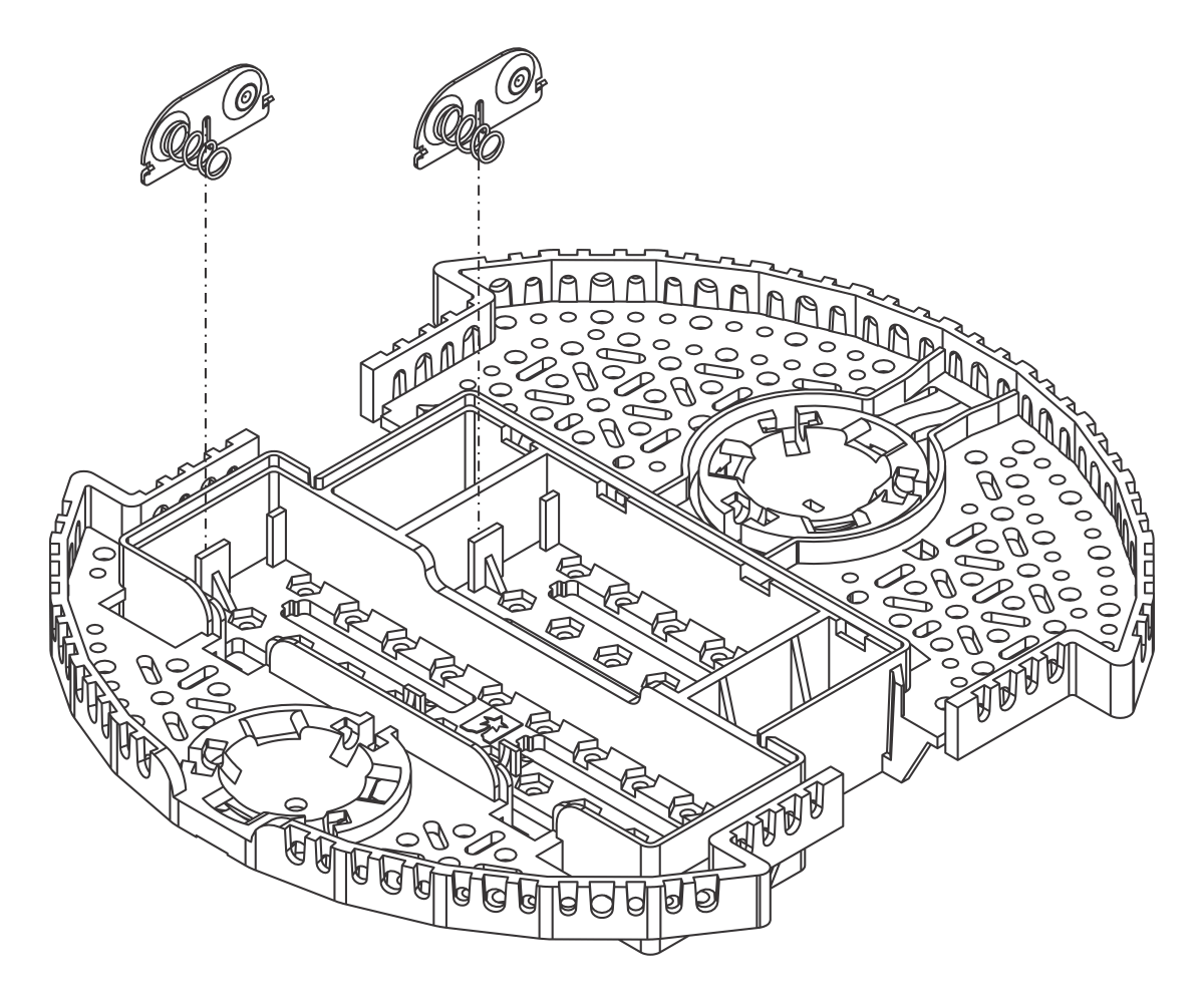 |
Installing the double-sided battery contacts in the Romi chassis. |
|---|
Then, insert the four single contacts from the top. They should rest loosely on the slots inside the battery holder, so that after soldering they can be easily removed:
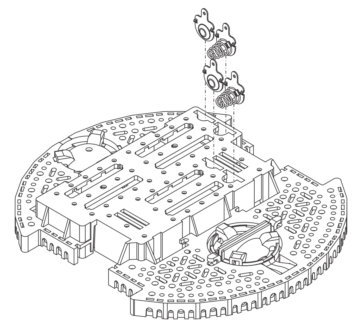 |
Installing the individual battery contacts on the Romi chassis. |
|---|
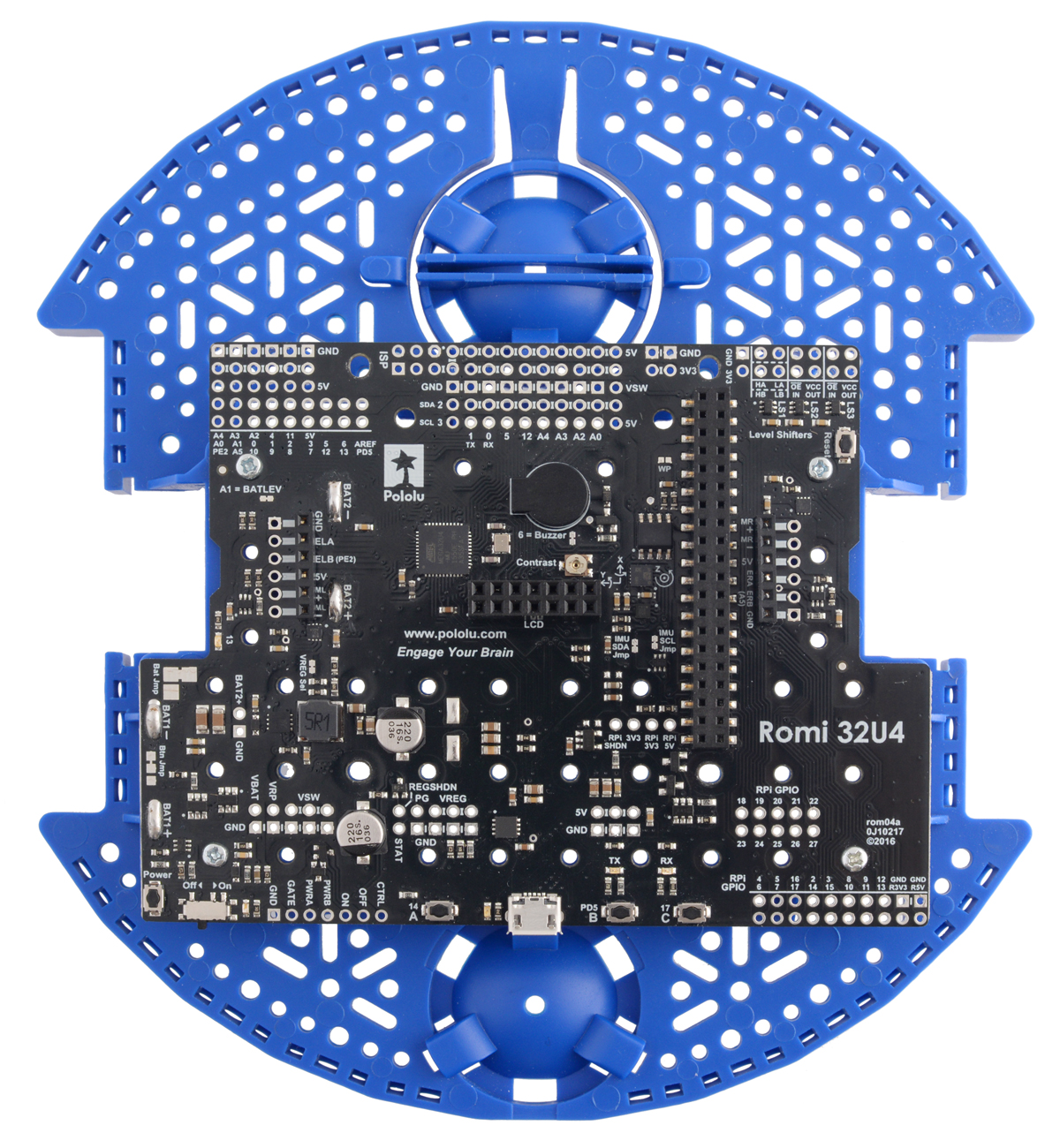
Now screw down the PCB with #2-56 screws and solder the four battery tabs.
 |
Snap in the motor brackets and assemble the ball caster (see detailed instructions in the Romi Chassis User’s Guide).
Note that the pictures in the Romi Chassis User’s Guide show a different orientation for the header pins on the encoder boards than what I recommended earlier for use with a Raspberry Pi, so follow the instructions below for soldering the encoder instead of the instructions in the chassis user’s guide.
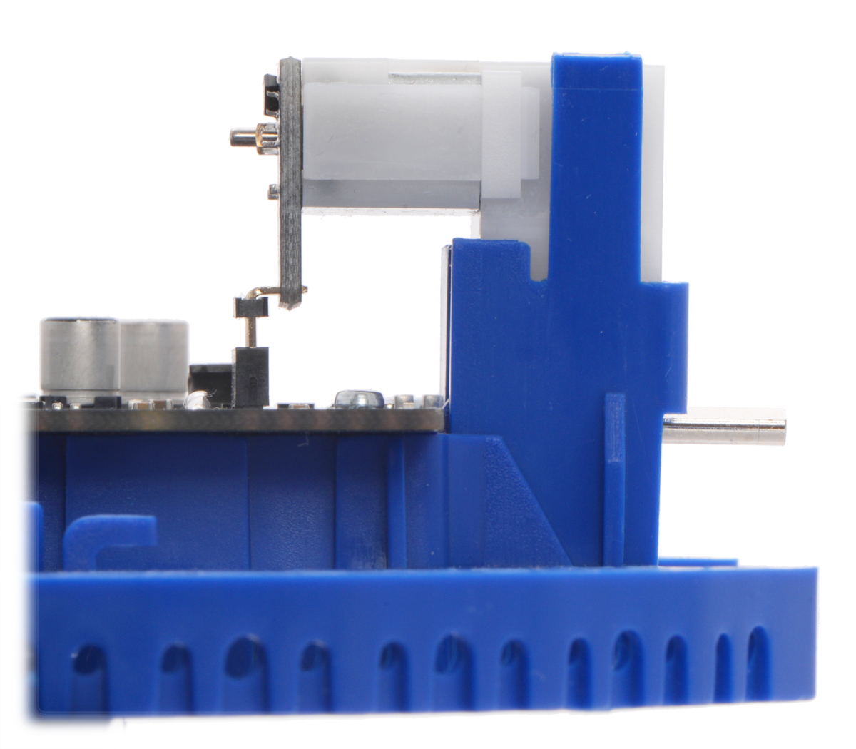
Next, solder your encoder boards to the back of your motors. To get good alignment for the connections between the encoders and Romi 32U4 Control Board, it is important that the encoder boards are flat against the motor and that the top of the boards line up well with the top surface of the motor as shown in the picture below.
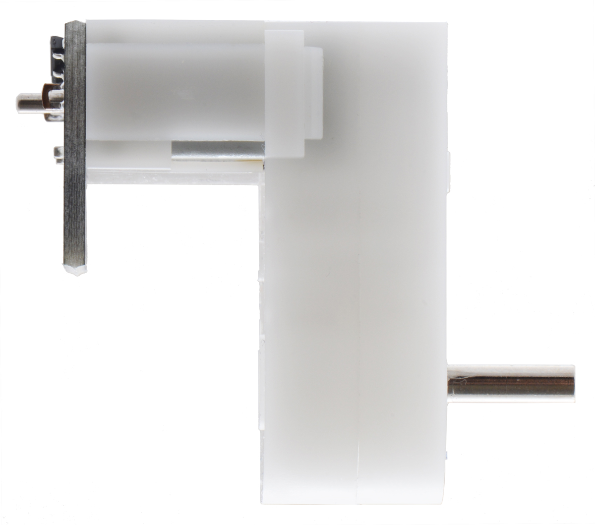 |
Mini Plastic Gearmotor with encoder board soldered flush against it. |
|---|
When you prepare to push the motors into their brackets, insert the male encoder headers into the holes in the encoder board and push the other ends down into the female headers on the control board as you push on the motors.
 |
Plugging the motor with encoder into the Romi before soldering the encoder header pins. |
|---|
Then solder them in place from the component side of the encoder board. Doing it this way guarantees those connections will all line up just right. Do not put the encoder discs on until you are done soldering, so you do not accidentally melt them with the iron.
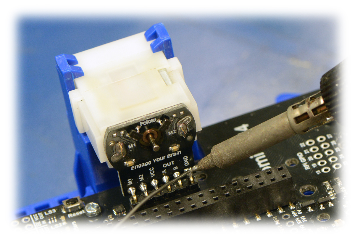 |
Soldering the header to the encoder board from the component side. |
|---|
Insert your batteries, push the encoder discs onto the motors, install the LCD if you are using one, and connect USB so you can test the motors and encoders. Load the Encoders example from the Romi library and then open up the Arduino serial monitor. Lastly, turn on the robot by pressing the power pushbutton, and test out the example. Note that the motors will not be powered from USB, so you must turn on the control board’s power switch. Pushing the A and C buttons on the control board should drive both motors forward and backward, and encoder counts will be printed in the serial monitor. If you have an LCD connected, the encoder counts will also be displayed there.
Before moving on and connecting the Raspberry Pi, make sure you reload the RomiRPiSlaveDemo.
Part 4: Test the server
To mount the Raspberry Pi on the robot you will need to remove the batteries and install the standoffs for your Pi with the threaded ends pointing down through the chassis. Also remove the LCD if it was installed.
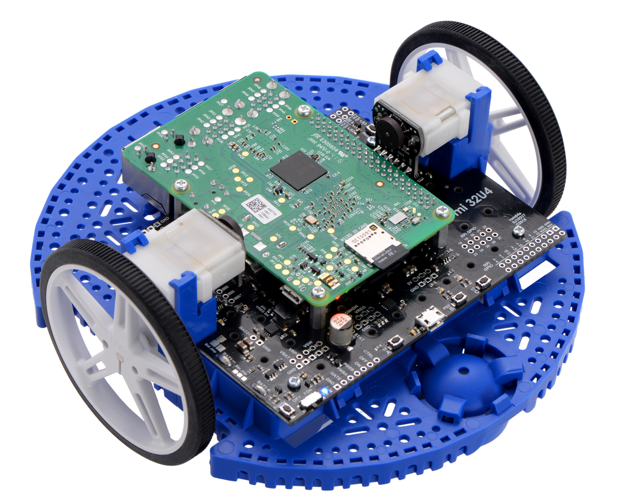 |
Mount the Raspberry Pi on the robot with the 20-pin connector and M2.5 screws. If you want to connect your Raspberry Pi to a monitor again, you will need to remove the left motor and then the motor bracket to give the HDMI cable room to plug in.
Now, try running the control panel server:
python3 pololu-rpi-slave-arduino-library/pi/server.py
The server starts up on port 5000, so you can access it at http://<ip>:5000/ where <ip> is the IP address of your Raspberry Pi. The server displays a simple control panel:
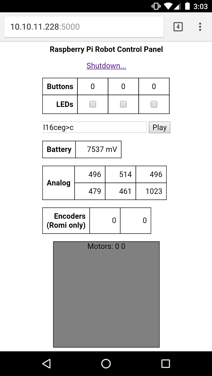 |
The upper part of the display allows you to interact with various parts of the Romi 32U4 Control Board: buttons, LEDs, buzzer, and analog voltage sensors, and you can touch or click within the gray square to command the robot to drive around. (The battery power switch must be ON for the motors to receive power from the batteries.) As you drive the motors, you should see the encoder counts updating.
Part 5: Start the server automatically
It’s annoying to have to log into the Raspberry Pi every time you start up your robot, so you will probably want to set up the server as a background service that starts automatically. With Raspbian Jessie and later, it’s easy to do this using systemd. Edit a file in the service directory:
sudo nano /lib/systemd/system/a_star_slave.service
Add the following lines (adjusting User and the path to server.py if necessary):
Description=Romi Slave Server
After=multi-user.target

[Service]
User=pi
Type=idle
ExecStart=/usr/bin/python3 /home/pi/pololu-rpi-slave-arduino-library/pi/server.py

[Install]
WantedBy=multi-user.target
There is also an included script that periodically pings the server to blink the LEDs as a heartbeat indicator. Edit a file for this service:
sudo nano /lib/systemd/system/a_star_heartbeat.service
Add the following lines, again adjusting User and the path if necessary:
Description=Romi Slave Heartbeat
After=multi-user.target

[Service]
User=pi
Type=idle
ExecStart=/usr/bin/python3 /home/pi/pololu-rpi-slave-arduino-library/pi/heartbeat.py

[Install]
WantedBy=multi-user.target
Enable and start these services:
sudo systemctl enable a_star_slave
sudo systemctl enable a_star_heartbeat
sudo systemctl start a_star_slave
sudo systemctl start a_star_heartbeat
Expansion Ideas
Now that you have the basics of controlling your Romi chassis from a Raspberry Pi down, here are a few fun project ideas that take advantage of the Raspberry Pi’s processing power and the Romi’s encoders:
- Mapping a space with a camera and distance data from the encoders.
- Looped maze solving or dead reckoning.
- Calculating and driving a path based on a line processed from an image file.
If you try out one of those project ideas, or any other project with a Romi and Raspberry Pi, we would love to hear about it and see pictures of what you made. Please share in the comments below! If you have technical issues getting the project to work, however, and you need some help, it’s better to go through technical support.
Related products


-
Verbal Machines VM-CLAP1 Hand Clap Sensor
- 14 April 2017Don’t hold your applause: we are now offering the Verbal Machines VM-CLAP1 Hand Clap Sensor! This board is a low-power, microprocessor-based audio...
-
Wall Power Adapter: 5.25VDC, 2.4A, 20AWG MicroUSB Cable
- 17 April 2017We’ve added this Micro-USB wall adapter to our catalog. It can supply up to 2.4 A at 5.25 VDC (the USB specification’s maximum bus voltage),...
7 comments


You can just call
a_star.motors(200,200); the int() function is for converting strings to integers. Also, we noticed that you created your own topic on our forum:
https://forum.pololu.com/t/romi-raspberry-pi-motor-control/15704
The forum is our preferred place for troubleshooting code, so please continue your discussion there.
-Jon

Thanks for letting us know; we've updated our posts.
-Jon


The forum is a better setting for troubleshooting, so please post about the issue there:
https://forum.pololu.com/
-Derrill

Post a comment


Home | Forum | Blog | Support | Ordering Information | Lists | Distributors | BIG Order Form | About | Contact
© 2001–2026 Pololu Corporation
