Pololu Blog » User Profile: Ben » Posts by Ben »
Posts by Ben (Page 4)
You are currently viewing a selection of posts from the Pololu Blog. You can also view all the posts.
Popular tags: community projects new products raspberry pi arduino more…
Our Black Friday/Cyber Monday sale has started!

Our Black Friday / Cyber Monday sale is going strong, and we have been working hard to make and ship the products that people are getting great deals on. Most of the sale coupons can be used on backorders if we happen to run out of stock, but you should still get your orders in early since lead times on some popular products can get long.
Please note that our usual same-day shipping guarantee is suspended during the sale, though so far we have been able to keep up with orders as they have been coming in, and we are closed Thursday, Nov 28th (tomorrow) for Thanksgiving. Happy Thanksgiving!
New product: Toshiba TB67S128FTG stepper driver carrier
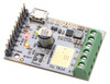
Our wide selection of stepper motor drivers has grown once again, this time with the addition of a full breakout board for Toshiba’s TB67S128FTG. The TB67S128FTG has many of the same great innovative features as the TB67S2x9FTG carriers we released last year, including Active Gain Control (AGC) for automatically reducing the current when full torque is not needed and Advanced Dynamic Mixed Decay (ADMD) for smoother, more even microsteps. On top of that, it adds features such as microstepping down to 1/128th-step and an optional serial interface. The driver offers a wide operating voltage range of 6.5 V to 44 V, and it can deliver 2.1 A per phase continuous (5 A peak) on our carrier board without any heat sink or forced air flow, making it our highest-current integrated driver (bested only by our discrete MOSFET High-Power Stepper Motor Driver 36v4).
These stepper motor driver carriers first debuted at Toshiba’s booth at Maker Faire Tokyo in August, and now that we finally have the drivers in volume, we are able to offer them to you! All of the driver’s control pins and outputs are available, so it can function as a complete evaluation board for the TB67128FTG, yet it is compact enough to integrate into actual projects without taking up an excessive amount of space:
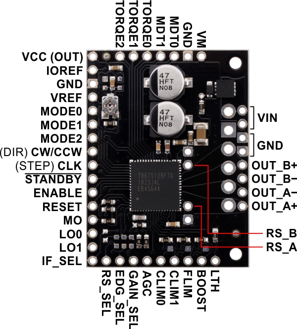 |
TB67S128FTG Stepper Motor Driver Carrier, top view with labeled pinout. |
|---|
Introductory special
As with all of our new product announcements, we are offering an introductory discount to make it extra easy to try out this new driver. Be among the first 100 customers to use coupon code TB67S128INTRO (click to add the coupon code to your cart) and up to three units for just $7.95 each.
Related products

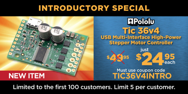
New product: Tic 36v4 USB Multi-Interface High-Power Stepper Motor Controller
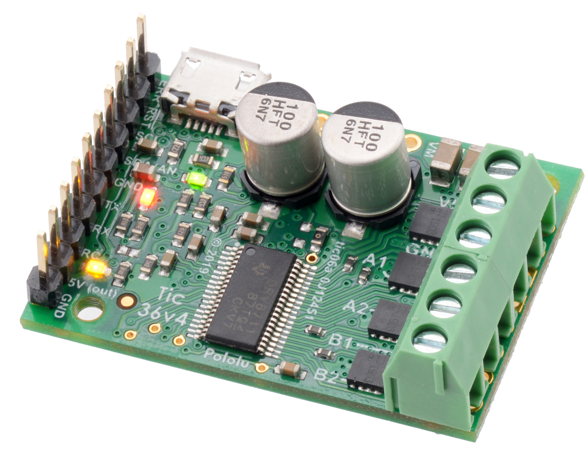 |
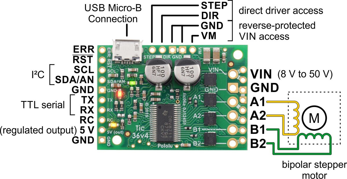
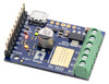
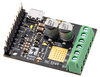
I am pleased to announce the release of the Tic 36v4 USB Multi-Interface High-Power Stepper Motor Controller, the fifth model in our line of Tic Stepper Motor Controllers. The Tic 36v4 features a discrete MOSFET stepper motor driver that can deliver up to approximately 4 A per phase, without a heat sink or forced air flow, over a broad 8 V to 50 V operating range. With the ability to provide more than twice as much current as any of our previous stepper motor controllers, this is our highest-power Tic yet, and the first that can drive the most demanding stepper motors we carry (#1474 and #1478) with their full rated current (2.8 A).
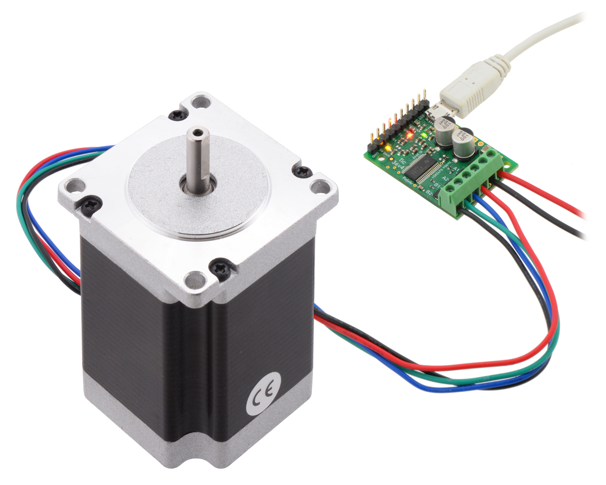 |
Tic 36v4 USB Multi-Interface High-Power Stepper Motor Controller controlling a #1478 stepper motor from USB. |
|---|
The Tic 36v4 supports microstepping resolutions down 1/256 step, which is 8 times smaller than any previous Tic model. These new, finer microstep resolutions make it increasingly important to be able to take steps at a high speed since with microsteps that small, it takes up to 51,200 of them to complete one revolution on standard stepper motors with 200 full steps per revolution. The Tic firmware takes care of that for you: it is designed to be able to produce up to 50,000 steps per second, meaning that you can get 58 RPM out of most of our stepper motors even when using 1/256 step mode. Every power of two step mode between full stepping and 1/256 is supported, allowing you to choose the right trade-off between speed and resolution.
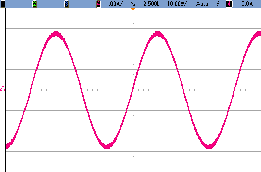 |
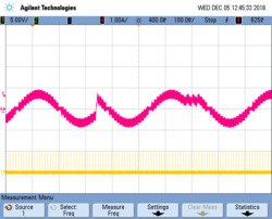
An oscilloscope capture showing the current through one coil of a stepper motor as the Tic 36v4 takes 25600 microsteps per second in 1/256 step mode. |
|---|
By default, the Tic 36v4 uses an automatic mixed decay mode for current regulation. In this mode, it dynamically selects between fast or slow decay based on the actual coil current, allowing it to achieve extremely smooth stepping in most applications without a lot of manual tuning—especially at high microstepping resolutions. (Isn’t that a nice sine wave in the picture above?)
However, if you want more control, this Tic also gives you the option to select a fixed decay mode and adjust several timing parameters to fine-tune the current decay behavior. This can be easily done with the Tic’s free graphical configuration software.
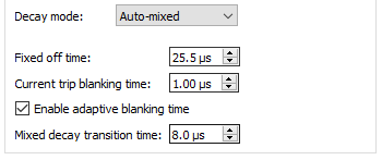 |
The decay mode settings for the Tic 36v4 in the Tic Control Center software. |
|---|
Like the other members of the Tic family, the Tic 36v4 makes basic speed or position control of a stepper motor easy, with lots of configurable parameters (e.g. max speed and acceleration) and support for six high-level control interfaces:
- USB for direct connection to a computer
- TTL serial operating at 5 V for use with a microcontroller
- I²C for use with a microcontroller
- RC hobby servo pulses for use in an RC system
- Analog voltage for use with a potentiometer or analog joystick
- Quadrature encoder input for use with a rotary encoder dial, allowing full rotation without limits (not for position feedback)
 |
This video gives a brief demonstration of these interfaces in action:
The Tic 36v4 is available with connectors soldered in or without connectors soldered in. If you do not need the high-level interfaces provided by the Tic, we also offer the Pololu High-Power Stepper Motor Driver 36v4.
Here is a handy comparison chart with all five Tic stepper motor controllers:
 Tic T500 |
 Tic T834 |
 Tic T825 |
 Tic T249 |
 Tic 36v4 |
|
|---|---|---|---|---|---|
| Operating voltage range: | 4.5 V to 35 V(1) | 2.5 V to 10.8 V | 8.5 V to 45 V(1) | 10 V to 47 V(1) | 8 V to 50 V(1) |
| Max continuous current per phase (no additional cooling): |
1.5 A | 1.5 A | 1.5 A | 1.8 A | 4 A |
| Peak current per phase (additional cooling required): |
2.5 A | 2 A | 2.5 A | 4.5 A | 6 A |
| Microstep resolutions: | full half 1/4 1/8 |
full half 1/4 1/8 1/16 1/32 |
full half 1/4 1/8 1/16 1/32 |
full half 1/4 1/8 1/16 1/32 |
full half 1/4 1/8 1/16 1/32 1/64 1/128 1/256 |
| Automatic decay selection: |  |
|
|
||
| Automatic gain control (AGC): | |
||||
| Driver IC: | MP6500 | DRV8834 | DRV8825 | TB67S249FTG | discrete MOSFETs |
| Price (connectors not soldered): | $32.95 | $42.95 | $42.95 | $52.95 | $62.95 |
| Price (connectors soldered): | $34.95 | $44.95 | $44.95 | $54.95 | $64.95 |
1 See product pages and user’s guide for operating voltage limitations.
Introductory special
As usual, we are offering an extra introductory special discount on the Tic 36v4, to help share in our celebration of releasing a new product. The first hundred customers to use coupon code TIC36V4INTRO can get up to five units for just $24.95! And we’ll even cover the shipping in the US!
Related products


New high-gear ratio Micro Metal Gearmotors
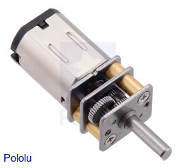
Our Micro Metal Gearmotors are now available with 380:1 gearboxes, offering a new high gear ratio option between our existing 298:1 and 1000:1 versions. Unlike the 1000:1 gearmotors, which uniquely require a longer, more expensive gearbox to achieve such a big reduction, the 380:1 gearboxes fit everything in the same volume as all our lower gear ratios, so they are the same price as those lower-ratio versions and they work with all our micro metal gearmotor brackets.
What really sets these new units apart from our other gear ratios are their stainless steel gearbox plates, which are more durable than the ubiquitous brass ones, especially in applications with non-negligible radial loads. They also look way cooler! Continued…
New 5:1 Glideforce light-duty linear actuators
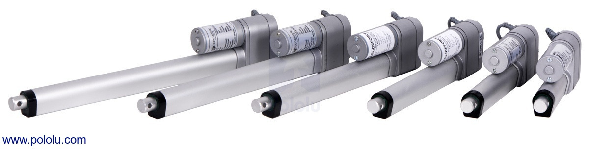 |
We have filled out our line of 5:1 Glideforce Light-Duty Linear Actuators to include all of Concentric’s available lengths by adding 2″, 6″, 8″, and 10″ versions, with and without feedback, to our existing 4″ and 12″ options. The low gear ratio makes these our fastest (but weakest) linear actuators, capable of lifting up to a few dozen pounds at speeds up to 1.7″ per second (44 mm/s) at 12 V. For stronger but slower options, we have versions available with a 10:1 gear ratio or 20:1 gear ratio.
This brings our total selection of light-duty actuators to 36 options:
| Actuator Type |
Max Dynamic Load |
No-Load Speed @ 12 V |
Max-Load Speed @ 12 V |
Current Draw @ 12 V |
Nominal Stroke Length |
With Feedback |
Without Feedback |
|---|---|---|---|---|---|---|---|
| Light-Duty (LD) 5:1 |
15 kgf [34 lbs] |
4.4 cm/s [1.7″/s] |
3.6 cm/s [1.4″/s] |
1.2 A – 3.2 A |
2″ | LACT2P-12V-05 | LACT2-12V-05 |
| 4″ | LACT4P-12V-05 | LACT4-12V-05 | |||||
| 6″ | LACT6P-12V-05 | LACT6-12V-05 | |||||
| 8″ | LACT8P-12V-05 | LACT8-12V-05 | |||||
| 10″ | LACT10P-12V-05 | LACT10-12V-05 | |||||
| 12″ | LACT12P-12V-05 | LACT12-12V-05 | |||||
| Light-Duty (LD) 10:1 |
25 kgf [55 lbs] |
2.8 cm/s [1.1″/s] |
2.3 cm/s [0.9″/s] |
1.2 A – 3.2 A |
2″ | LACT2P-12V-10 | LACT2-12V-10 |
| 4″ | LACT4P-12V-10 | LACT4-12V-10 | |||||
| 6″ | LACT6P-12V-10 | LACT6-12V-10 | |||||
| 8″ | LACT8P-12V-10 | LACT8-12V-10 | |||||
| 10″ | LACT10P-12V-10 | LACT10-12V-10 | |||||
| 12″ | LACT12P-12V-10 | LACT12-12V-10 | |||||
| Light-Duty (LD) 20:1 |
50 kgf [110 lbs] |
1.5 cm/s [0.57″/s] |
1.2 cm/s [0.48″/s] |
1.2 A – 3.2 A |
2″ | LACT2P-12V-20 | LACT2-12V-20 |
| 4″ | LACT4P-12V-20 | LACT4-12V-20 | |||||
| 6″ | LACT6P-12V-20 | LACT6-12V-20 | |||||
| 8″ | LACT8P-12V-20 | LACT8-12V-20 | |||||
| 10″ | LACT10P-12V-20 | LACT10-12V-20 | |||||
| 12″ | LACT12P-12V-20 | LACT12-12V-20 | |||||
Related products


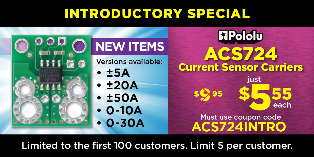
New products: ACS724 current sensor carriers
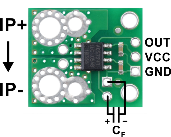 |
We now have new current sensors based on Allegro’s ACS724, the successor to the ACS714 that we have been using for many years. The ACS724 offers a number of exciting improvements over the ACS714, including more current range options (up to ±50 A!), over twice the sensitivity for the ±5 A version, a higher bandwidth for faster response times, and differential Hall sensing for substantially reduced interference from ambient magnetic fields. In quick tests, we saw a variation of around 1% of the full range just from changing the orientation of the ACS714 in space (because of the Earth’s magnetic field), while the ACS724 output stayed steady regardless of orientation. We also tried bringing a small magnet close to each sensor, and its effect on the output was many times smaller on the ACS724.
These bidirectional and unidirectional current sensors are a simple way to gain fundamental insight into the performance of your system. You can use them for closed-loop torque control of actuators, tracking power consumption over time, or even as inexpensive current probes for an oscilloscope. They output an analog voltage that varies linearly with the current passing through them, and because they use the Hall effect to measure the current, they offer full electrical isolation of the current path from the sensor’s electronics. This method of sensing means the sensor can be inserted anywhere into the current path, including on the high side, and because their current path resistance is on the order of 1 mΩ or less, they have minimal effect on the rest of the system.
Five different current ranges are available:- ACS724 Current Sensor Carrier -5A to +5A
- ACS724 Current Sensor Carrier -20A to +20A
- ACS724 Current Sensor Carrier -50A to +50A
- ACS724 Current Sensor Carrier 0A to 10A
- ACS724 Current Sensor Carrier 0A to 30A
Together with the Broadcom ACHS-712x current sensors we released last month, this brings our full current sensor lineup to thirteen sensors:
 ACS709 Current Sensor Carrier |
 ACS711EX Current Sensor Carriers |
 ACS714 Current Sensor Carriers |
ACS724 Current Sensor Carriers |
ACHS-712x Current Sensor Carriers |
|||||||
|---|---|---|---|---|---|---|---|---|---|---|---|
| Sensor IC: | ACS709 | ACS711EX | ACS714 | ACS724 | ACHS-712x | ||||||
| Current range / sensitivity(1): | ±75 A / 28 mV/A | ±15.5 A / 136 mV/A ±31 A / 68 mV/A |
±5 A / 185 mV/A ±30 A / 66 mV/A |
0–10 A / 400 mv/A 0–30 A / 133 mV/A ±5 A / 400 mV/A ±20 A / 100 mV/A ±50 A / 40 mV/A |
±10 A / 185 mV/A ±20 A / 100 mV/A ±30 A / 66 mV/A |
||||||
| Path resistance: | 1.1 mΩ | 0.6 mΩ | 1.2 mΩ | 1.2 mΩ | 0.7 mΩ | ||||||
| Bandwidth | 120 kHz | 100 kHz | 80 kHz | 120 kHz | 80 kHz | ||||||
| Vcc range:(1) | 3 V–5.5 V | 3 V–5.5 V | 4.5 V–5.5 V | 4.5 V–5.5 V | 4.5 V–5.5 V | ||||||
| Size: | 0.82″ × 0.9″ | 0.7″ × 0.8″ | 0.7″ × 0.8″ | 0.7″ × 0.8″ | 0.7″ × 0.8″ | ||||||
| Special features: | configurable over-current threshold, low-voltage operation, high bandwidth |
over-current fault pin, low-voltage operation |
Differential Hall sensing rejects common-mode fields, high bandwidth |
||||||||
| 1-piece price: | $5.95 | $4.85 | $19.95 | $9.95 | $6.95 | ||||||
| 1 Sensitivity based on when Vcc is 5V. | |||||||||||
Introductory special
As usual, we are offering an extra introductory special discount on the ACS724 current sensor carriers, to help share in our celebration of releasing a new product. The first hundred customers to use coupon code ACS724INTRO can get up to five units for just $5.55 each!
Related products


New products: D36V28Fx Step-Down Voltage Regulators
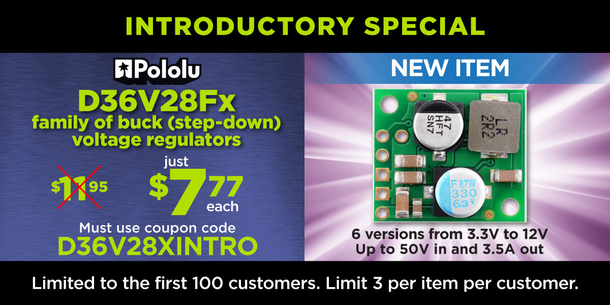 |
I am happy to announce the release of our newest regulators, the D36V28Fx family of step-down voltage regulators. These regulators support a wide input voltage range (up to 50 V!) and can deliver up to 4 A, making them well suited for use with power-hungry processors like the Raspberry Pi and projects involving servos or small motors.
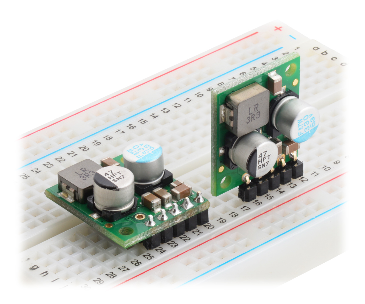 |
Step-Down Voltage Regulator D36V28Fx, assembled on breadboard. |
|---|
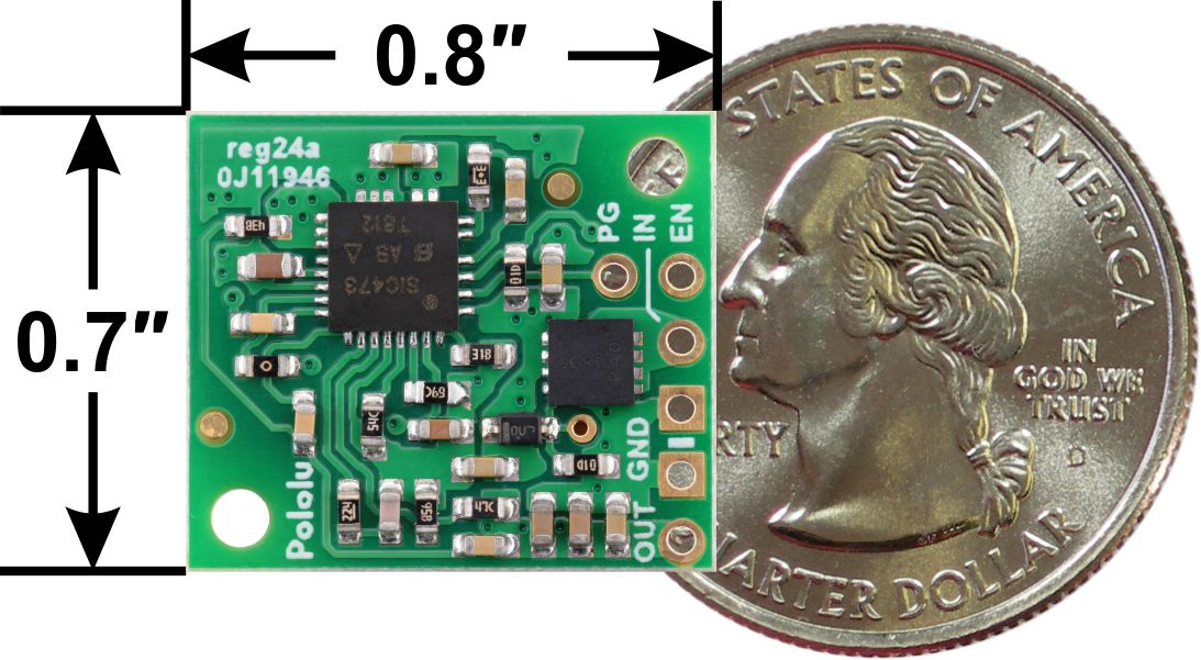 |
Step-Down Voltage Regulator D36V28Fx, bottom view with dimensions. |
|---|
The family consists of six fixed output voltage versions between 3.3 V and 12 V:
- D36V28F3: Fixed 3.3V output
- D36V28F5: Fixed 5V output
- D36V28F6: Fixed 6V output
- D36V28F7: Fixed 7.5V output
- D36V28F9: Fixed 9V output
- D36V28F12: Fixed 12V output
And since we make these ourselves here in Las Vegas, we can also quickly make versions with custom output voltages; please contact us us for more information.
Comparison to the D24V22Fx step-down regulator family
|
|


The D36V28Fx family now becomes our recommended alternative to the slightly smaller D24V22Fx if you need a little more power or operation above 36 V:
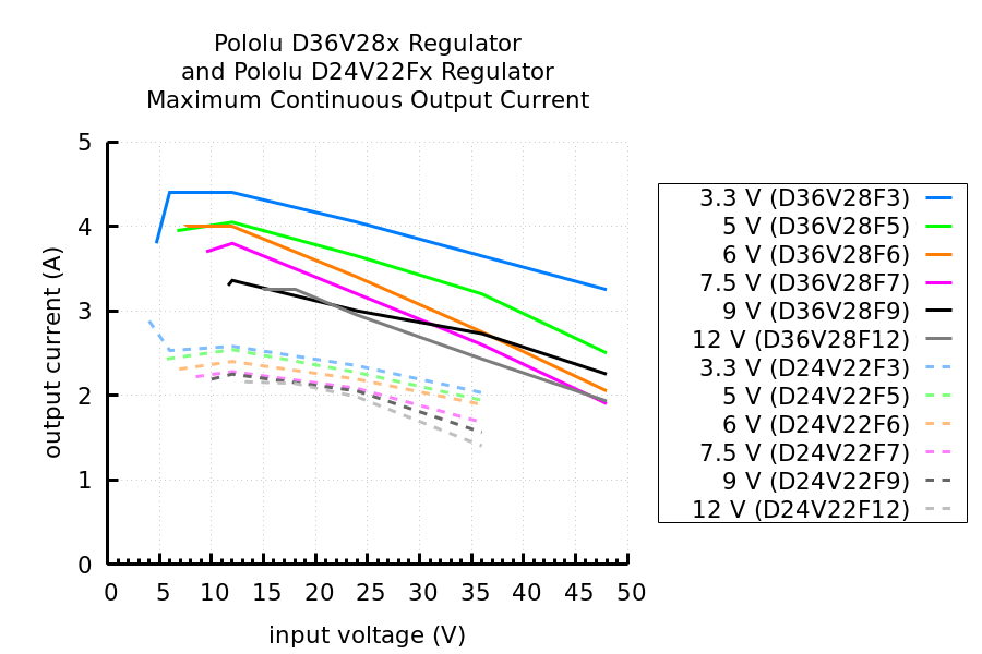 |
Comparison of the maximum continuous current of Step-Down Voltage Regulators D36V28Fx and D24V22Fx. |
|---|
The D24V22Fx still outperforms the D36V28Fx when it comes to dropout voltage and quiescent current:
 |
Comparison of the dropout voltage of Step-Down Voltage Regulators D36V28Fx and D24V22Fx. |
|---|
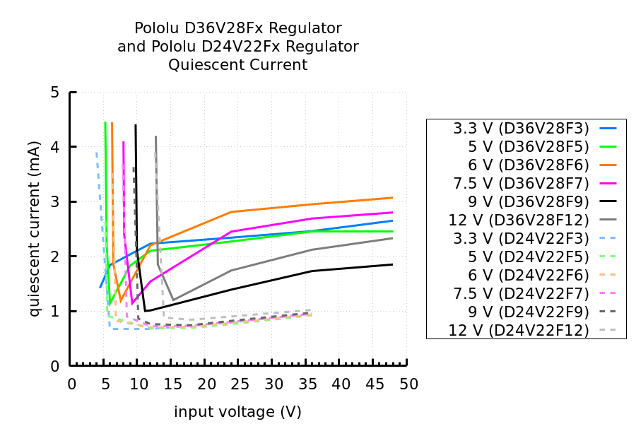 |
Comparison of the quiescent current of Step-Down Voltage Regulators D36V28Fx and D24V22Fx. |
|---|
Introductory special
As usual, we are offering an extra introductory special discount on these new regulators, to help share in our celebration of releasing a new product. The first hundred customers to use coupon code D36V28XINTRO can get up to three units for just $7.77 each!
Related products


New Tic T500 revision to address problem with missed steps
One of the fun things you learn as an engineer is that physically laying out a circuit requires a lot more than simply confirming it matches the schematic. In practice, there are many more things to think about, and if you’ve seen datasheets with layout guidelines or recommendations, you’re probably aware of some of them. (Thermal considerations, adequate decoupling, minimizing parasitic inductance and capacitance…) What’s more, these considerations are often in conflict (e.g. is it better to have the decoupling capacitor closer to the IC or to have a wider trace for that high-current path?), and trouble can arise if you don’t correctly assess their relative importance. That is what happened to us with our Tic T500 stepper motor controller, where the location of a specific decoupling capacitor ended up being far more significant than we had anticipated. Continued…
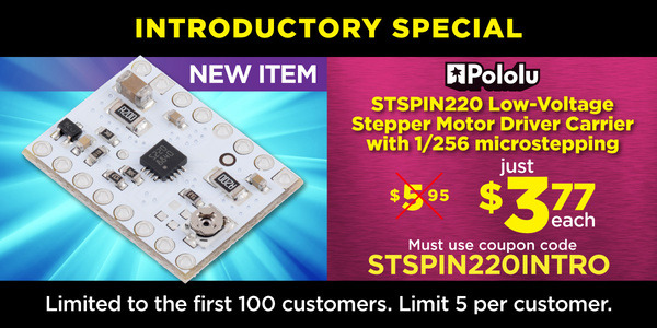
New product: STSPIN220 Low-Voltage Stepper Motor Driver Carrier with 1/256 microstepping
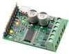
I am happy to announce our first new product of 2019, a carrier board for the STSPIN220 stepper motor driver, which operates all the way down to 1.8 V, making it our lowest-voltage stepper motor driver. And like its higher-voltage sibling, the STSPIN820 that we released a few months ago, it offers microstepping down to 1/256 steps. This new carrier board has the same 16-pin, 0.6″ × 0.8″ form factor as our other popular stepper motor drivers, and as with our STSPIN820 carrier, it inverts the enable input so that it has the more familiar functionality of those drivers (but be careful not to pop these into a 12 V or 24 V socket!).
By the way, keep in mind that you do not necessarily need a low-voltage stepper motor driver just because your stepper motor has a low rated voltage. The voltage rating is just the voltage at which your stepper motor will draw its rated current, and it’s really the current rating that you need to be careful about if you want to avoid damaging your stepper motor. All of our stepper motor drivers let you limit the maximum current, so as long as you set the limit below the rated current, you will be within spec for your motor, even if the voltage exceeds the rated voltage. In general, using a high supply voltage along with active current limiting allows for better performance, so the main reason for using a low-voltage stepper motor driver like the STSPIN220 is if your supply voltage is constrained to some low value by some other aspect of your system.
This new release brings our selection of stepper motor drivers in this compact form factor to eleven:
 A4988 (original) |
 A4988, Black Ed. |
 DRV8825 |
 DRV8834 |
 DRV8880 |
 MP6500, Pot. CC |
 MP6500, Digital CC |
 TB67S279FTG |
 TB67S249FTG |
 STSPIN820 |
 STSPIN220 |
|
|---|---|---|---|---|---|---|---|---|---|---|---|
| Driver chip: | A4988 | DRV8825 | DRV8834 | DRV8880 | MP6500 | TB67S279FTG | TB67S249FTG | STSPIN820 | STSPIN220 | ||
| Min operating voltage: | 8 V | 8.2 V | 2.5 V | 6.5 V | 4.5 V | 10 V | 10 V | 7 V | 1.8 V | ||
| Max operating voltage: | 35 V | 45 V | 10.8 V | 45 V | 35 V | 47 V | 47 V | 45 V | 10 V | ||
| Max continuous current per phase:(1) | 1 A | 1.2 A | 1.5 A | 1.5 A | 1 A | 1.5 A | 1.1 A | 1.6 A | 0.9 A | 1.1 A | |
| Peak current per phase:(2) | 2 A | 2.2 A | 2 A | 1.6 A | 2.5 A | 2 A | 2 A | 4.5 A | 1.5 A | 1.3 A | |
| Microstepping down to: | 1/16 | 1/32 | 1/32 | 1/16 | 1/8 | 1/32 | 1/32 | 1/256 | 1/256 | ||
| Board layer count: | 2 | 4 | 4 | 4 | 4 | 4 | 4 | 4 | 4 | 4 | |
| Special features: | high current | low-voltage operation, high current |
AutoTune, digital current reduction |
high current | digital current control, high current |
Auto Gain Control, ADMD, high max voltage |
Auto Gain Control, ADMD, high max voltage, high current |
128 and 256 microsteps, high max voltage |
64, 128, and 256 microsteps, low-voltage operation |
||
| 1-piece price: | $8.95 | $9.95 | $15.95 | $9.95 | $8.95 | $9.95 | $9.95 | $11.75 | $13.95 | $18.95 | $10.95 |
| 1 On Pololu carrier board, at room temperature, and without additional cooling. 2 Maximum theoretical current based on components on the board (additional cooling required). |
|||||||||||
Last year, we began offering introductory specials to celebrate each newly released product, and we are continuing with that this year: the first 100 customers that use coupon code STSPIN220INTRO can get up to five units at just $3.77 each.
Related products


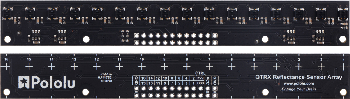
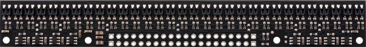
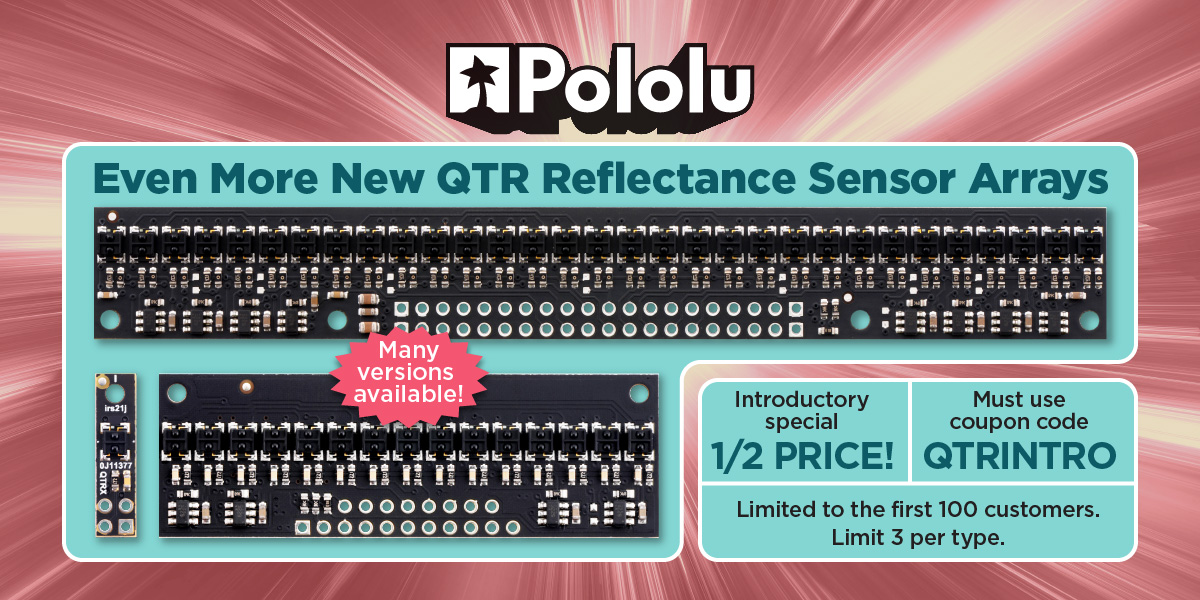
New products: 16-channel QTR MD reflectance sensor arrays
 |
 |
QTR-MD-16A Reflectance Sensor Array. |
|---|
We now have 16-sensor, medium-density (8mm-pitch) versions of our new QTR reflectance sensor arrays. Like the versions already released, these new modules are available in analog and RC configurations and with two different sensor types, resulting in four new products in all:
- QTR-MD-16RC Reflectance Sensor Array
- QTR-MD-16A Reflectance Sensor Array
- QTRX-MD-16RC Reflectance Sensor Array
- QTRX-MD-16A Reflectance Sensor Array
Unlike the medium-density (MD) arrays we have released previously, which just use the high-density PCBs in partially populated configurations, these new 16-channel modules use PCBs specifically designed for an 8 mm pitch. As a result, these are the first MD versions that allow separate control of the odd and even emitters, which gives you extra options for detecting light reflected at various angles. They have the same board dimensions (125 × 16.5 mm) and mounting hole locations as the high-density (4mm-pitch) 31-channel arrays, but the pinout is different.
 |
QTR-MD-16A Reflectance Sensor Array. |
|---|
 |
QTR-HD-31A Reflectance Sensor Array. |
|---|
For more information on our new QTR sensor family, you can see some of our previous blog posts about the versions we have already released:
- New products: 1- and 31-channel QTR HD reflectance sensor arrays
- New products: more new QTR HD sensor arrays by student engineering interns
- New products: QTR HD sensor arrays by student engineering interns
- New product: high-density QTR reflectance sensor arrays
Don’t forget to get in on our QTR introductory promotion! Be one of the first 100 customers to use coupon code QTRINTRO and get any of these new sensors at half price! (Limit 3 per item per customer.)
Related products


Home | Forum | Blog | Support | Ordering Information | Lists | Distributors | BIG Order Form | About | Contact
© 2001–2026 Pololu Corporation


