ACS714 Current Sensor Carrier -5A to +5A

This board is a simple carrier of Allegro’s ±5A ACS714 Hall effect-based linear current sensor, which offers a low-resistance (~1.2 mΩ) current path and electrical isolation up to 2.1 kV RMS. This version accepts a bidirectional current input with a magnitude up to 5 A and outputs a proportional analog voltage (185 mV/A) centered at 2.5 V with a typical error of ±1.5%. It operates from 4.5 V to 5.5 V and is intended for use in 5 V systems.
| Description | Specs (9) | Pictures (3) | Resources (4) | FAQs (0) | On the blog (0) | Distributors (0) |
|---|
Recommended replacement: Please consider the newer ACS724 current sensor carrier -5A to +5A as an alternative product. It has the same physical dimensions and pinout and offers greater sensitivity and improved accuracy.
Overview
 |
This current sensor is a carrier board or breakout board for Allegro’s ACS714LLCTR-05B-T Hall effect-based linear current sensor; we therefore recommend careful reading of the ACS714 datasheet (701k pdf) before using this product. The sensor operates at 5 V and has an output sensitivity of 185 mV/A. The board ships fully populated with its SMD components, including the ACS714, as shown in the product picture. The following list details some of the sensor’s key features:
- Designed for bidirectional input current from -5 A to 5 A (though the robust sensor IC can survive up to five times the overcurrent condition).
- Conductive path internal resistance is typically 1.2 mΩ, and the PCB is made with 2-oz copper, so very little power is lost in the board.
- Use of a Hall effect sensor means the IC is able to electrically isolate the current path from the sensor’s electronics (up to 2.1 kV RMS), which allows the sensor to be inserted anywhere along the current path and to be used in applications that require electrical isolation.
- 80 kHz bandwidth that can optionally be decreased by adding a capacitor across the board pins marked “filter”.
- High accuracy and reliability: typical total output error of ±1.5% at room temperature with factory calibration, an extremely stable output offset voltage, and almost zero magnetic hysteresis.
- Automotive-grade operating temperature range of -40°C to 150°C.
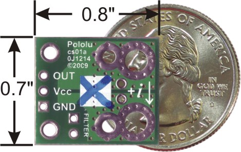
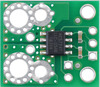
The pads are labeled on the bottom silkscreen, as shown in the picture to the right. The silkscreen also shows the direction that is interpreted as positive current flow via the +i arrow.
Like almost all our carrier boards, this sensor ships assembled with all of its required surface mount components, as shown in the main product picture.
This version is marked with a blue X. We also sell a ±30A bidirectional version of this board; you can distinguish these versions by reading the text on the IC or by looking at the color of the X on the bottom silkscreen.
Using the sensor
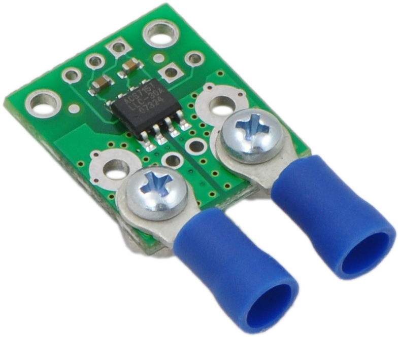 |
Current sensor carrier with solderless ring terminal connectors (not included). |
|---|
Electrical connections
The sensor requires a supply voltage of 4.5 V to 5.5 V to be connected across the Vcc and GND pads, which are labeled on the bottom silkscreen. The sensor outputs an analog voltage that is linearly proportional to the input current. When Vcc is 5 V, this output voltage is centered at 2.5 V and changes by 185 mV per amp of input current, with positive current increasing the output voltage and negative current decreasing the output voltage.
Warning: This product is intended for use below 30 V. Working with higher voltages can be extremely dangerous and should only be attempted by qualified individuals with appropriate equipment and protective gear.
The input current can be connected to the board in a variety of ways. For low-current applications, you can solder 0.1" male header pins to the board via the small through-holes on the input-current side of the board. For higher-current applications, you can solder wires directly to the through-holes whose sizes best match your wires, or you can use solderless ring terminal connectors, as shown in the picture to the right. The large through-holes are big enough for #6 screws.
Mounting information
The board has two mounting holes on the logic side of the board. These mounting holes are 0.5" apart and are designed for #2 screws.
Filtering the output
The IC has an internal filter resistance of 1.7 kΩ, and the carrier board includes a 1 nF filter capacitor, which produces a low-pass RC filter with a 90 kHz cutoff. You can improve sensing system accuracy for low-frequency sensing applictations by adding a capacitor in parallel with the integrated 1 nF capacitor across the pads marked “filter” on the bottom silkscreen (this capacitor is labeled C2b in the schematic below). The frequency F that the filter will attenuate to half its original power is given by:
``F = 1 / (2piRC) = 1 / (11 text( kΩ) * (1 text( nF) + C_f))``
where Cf is the value of the capacitor added to the filter pads.
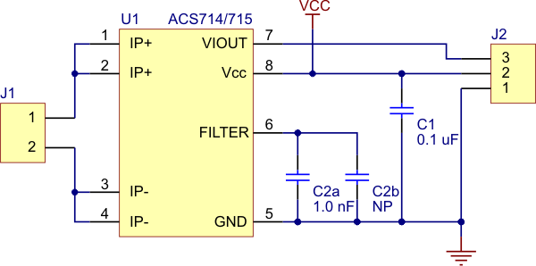 |
Pololu ACS714/ACS715 current sensor carrier schematic diagram. |
|---|
Comparison of the Pololu current sensor carriers
We have a variety of current sensors available with different ranges, sensitivities, and features. You can use the following table to compare our options:
 |
 |
 |
 |
 |
 |
 |
 |
 |
 |
|
|---|---|---|---|---|---|---|---|---|---|---|
| CT220 Contactless Current Sensor Carriers |
ACS3704x Current Sensor Micro Carriers |
ACS3704x Current Sensor Compact Carriers |
ACS711 Current Sensor Carriers |
ACS71240 Current Sensor Carriers |
ACS724 Current Sensor Carriers |
ACS37100 TMR Current Sensor Compact Carriers |
ACS37030LZ Current Sensor Compact Carriers |
ACS37030MY Current Sensor Compact Carriers |
CT432/CT433 TMR Current Sensor Compact Carriers |
|
| Allegro Sensor | CT220xMV-HS5 | ACS3704x | ACS711KEXT | ACS71240 | ACS724LLCTR | ACS37100 | ACS37030LLZ | ACS37030LMY | CT432/CT433 | |
| Sensing technology | XtremeSense™ TMR (tunneling magnetoresistance) |
Hall effect | Hall effect | Hall effect | Hall effect | XtremeSense™ TMR (tunneling magnetoresistance) |
Hall effect + inductive coil | XtremeSense™ TMR (tunneling magnetoresistance) |
||
| Logic voltage range | 2.7–5.5 V | 3.3V versions: 3.0–3.6 V 5V versions: 4.75–5.5 V |
3.0–5.5 V | 3.3V ver: 3.0–3.6 V 5V ver: 4.5–5.5 V |
4.5–5.5 V | 3.0–3.6 V | 3.0–3.6 V | 3.3V ver: 3.0–3.6 V 5V ver: 4.75–5.5 V |
||
| Family current range | 10–800 A | 10–30 A | 15.5–31 A | 10–50 A | 2.5–50 A | 25–50 A | 20–65 A | 20–70 A | ||
| Range/sensitivity of individual versions | (2) ±1.5 mT / 1500 mV/mT ±15 mT / 150 mV/mT |
ACS37041: 3.3V Bidirectional: ±10 A / 132 mV/A ±30 A / 44 mV/A 5V Bidirectional: ±10 A / 200 mV/A ±30 A / 66.7 mV/A ACS37042: 3.3V Bidirectional: ±10 A / 132 mV/A ±30 A / 44 mV/A 5V Bidirectional: ±10 A / 200 mV/A ±30 A / 66.7 mV/A |
ACS37041: 3.3V Bidirectional: ±10 A / 132 mV/A ±30 A / 44 mV/A 5V Bidirectional: ±10 A / 200 mV/A ±30 A / 66.7 mV/A ACS37042: 3.3V Bidirectional: ±10 A / 132 mV/A ±30 A / 44 mV/A 5V Bidirectional: ±10 A / 200 mV/A ±30 A / 66.7 mV/A |
Bidirectional:(1) ±15.5 A / 90 mV/A ±31 A / 45 mV/A |
3.3V Bidirectional: ±10 A / 132 mV/A ±30 A / 44 mV/A ±50 A / 26.4 mV/A 5V Bidirectional: ±10 A / 200 mV/A ±30 A / 66 mV/A ±50 A / 40 mV/A 5V Unidirectional: 0–50 A / 80 mv/A |
5V Bidirectional:(2) ±2.5 A / 800 mV/A ±5 A / 400 mV/A ±10 A / 200 mV/A ±20 A / 100 mV/A ±30 A / 66 mV/A ±50 A / 40 mV/A 5V Unidirectional:(2) 0–5 A / 800 mv/A 0–10 A / 400 mv/A 0–20 A / 200 mv/A 0–30 A / 133 mV/A |
3.3V Bidirectional: ±25 A / 52.8 mV/A ±50 A / 26.4 mV/A |
3.3V Bidirectional: ±20 A / 66 mV/A ±40 A / 33 mV/A ±65 A / 20.3 mV/A |
3.3V Bidirectional: ±20 A / 66 mV/A ±40 A / 33 mV/A ±65 A / 20.3 mV/A |
3.3V Bidirectional: ±20 A / 50 mV/A ±30 A / 33.3 mV/A ±50 A / 20 mV/A ±70 A / 14.3 mV/A 3.3V Unidirectional: 0–20 A / 100 mv/A 0–30 A / 66.7 mv/A 0–50 A / 40 mv/A 0–65 A / 30.8 mv/A 5V Bidirectional: ±20 A / 100 mV/A ±30 A / 66.7 mV/A ±50 A / 40 mV/A ±65 A / 30.8 mV/A 5V Unidirectional: 0–20 A / 200 mv/A 0–30 A / 133.3 mv/A 0–50 A / 80 mv/A 0–70 A / 57.1 mv/A |
| Max bandwidth | 30 kHz | 150 kHz | 100 kHz | 120 kHz | 120 kHz(3) | 10 MHz | 5 MHz | 1 MHz | ||
| IC current path resistance | N/A (contactless) | 1.6 mΩ | 0.6 mΩ | 0.6 mΩ | 0.6 mΩ | 1.2 mΩ | 0.7 mΩ | 0.9 mΩ | 1 mΩ | |
| IC isolation rating(6) | N/A (contactless) | ACS37041: 100 VRMS ACS37042: 285 VRMS |
100 Vpk | 100 Vpk | 297 VRMS | 1097 VRMS | 840 VRMS | 1000 VRMS | 1100 VRMS | |
| Minimum PCB creepage(7) | N/A (contactless) | ACS37041: 1.6 mm ACS37042: 2.0 mm |
ACS37041: 1.6 mm ACS37042: 3.0 mm |
0.75 mm | 0.75 mm | 1.1 mm | 9.3 mm | 4.1 mm | 11.7 mm | 8 mm |
| PCB | N/A (contactless) | 2 layers, 1-oz copper |
2 layers, 2-oz copper |
2 layers, 2-oz copper |
2 layers, 2-oz copper |
2 layers, 2- or 4-oz copper(4) |
2 layers, 2-oz copper |
2 layers, 2-oz copper |
2 or 4 layers(5), 2-oz copper |
|
| Size | 0.4″ × 0.62″ | 0.3″ × 0.4″ | 0.7″ × 0.8″ | 0.7″ × 0.8″ | 0.7″ × 0.8″ | 0.7″ × 0.8″ | 0.8″ × 1.1″ | 0.7″ × 0.8″ | 0.8″ × 1.1″ | 0.8″ × 1.1″ |
| Overcurrent fault output |
(configurable threshold) | |||||||||
| Common-mode field rejection | ||||||||||
| Nonratiometric output | ||||||||||
| 1-piece price | $4.95 | $4.15 – $4.69 | $4.45 – $4.99 | $4.85 | $5.25 | $9.95 – $11.49 | $14.95 | $8.95 | $12.95 | $12.95 |
Note 1: Sensitivity when Vcc = 3.3 V; actual sensitivity is ratiometric (i.e. it is proportional to Vcc).
Note 2: Sensitivity when Vcc = 5 V; actual sensitivity is ratiometric (i.e. it is proportional to Vcc).
Note 3: Bandwidth can be reduced by adding a filter capacitor.
Note 4: 50A version of this carrier uses 4-oz copper PCB; all other versions of this carrier use 2-oz copper.
Note 5: 50A and higher versions of this carrier use a 4-layer PCB; all other versions of this carrier use a 2-layer PCB.
Note 6: IC component rating per manufacturer datasheet.
Note 7: Minimum creepage along PCB surface based on layout design only. Other creepage distances, e.g. along the body of the component, may be lower.
|
 |
|
 |
|
 |
|
 |
 |
 |
 |
 |
 |
 |
|
|---|---|---|---|---|---|---|---|---|---|---|---|---|---|---|
| ACS37100 Current Sensor Compact Carriers |
ACS37100 Current Sensor Large Carriers |
ACS37030LZ Current Sensor Compact Carriers |
ACS37030LZ Current Sensor Large Carriers |
ACS37030MY Current Sensor Compact Carriers |
ACS37030MY Current Sensor Large Carriers |
CT432/CT433 TMR Current Sensor Compact Carriers |
CT432/CT433 TMR Current Sensor Large Carriers |
ACS72981 Current Sensor Compact Carriers |
ACS72981 Current Sensor Large Carriers |
ACS37220 Current Sensor Compact Carriers |
ACS37220 Current Sensor Large Carriers |
ACS37200 Current Sensor Compact Carriers |
ACS37200 Current Sensor Large Carriers |
|
| Allegro Sensor | ACS37100 | ACS37030LLZ | ACS37030LMY | CT432/CT433 | ACS72981xLR | ACS37220 | ACS37200 | |||||||
| Sensing technology | XtremeSense™ TMR (tunneling magnetoresistance) |
Hall effect + inductive coil | XtremeSense™ TMR (tunneling magnetoresistance) |
Hall effect | Hall effect | |||||||||
| Logic voltage range | 3.0–3.6 V | 3.0–3.6 V | 3.3V versions: 3.0–3.6 V 5V versions: 4.75–5.5 V |
3.3V versions: 3.0–3.6 V 5V versions: 4.5–5.5 V |
3.3V versions: 3.15–3.45 V 5V versions: 4.5–5.5 V |
|||||||||
| Family current range | 25–50 A | 20–65 A | 20–70 A | 50–200 A | 100–200 A | |||||||||
| Range/sensitivity of individual versions | 3.3V Bidirectional: ±25 A / 52.8 mV/A ±50 A / 26.4 mV/A |
3.3V Bidirectional: ±25 A / 52.8 mV/A ±50 A / 26.4 mV/A |
3.3V Bidirectional: ±20 A / 66 mV/A ±40 A / 33 mV/A ±65 A / 20.3 mV/A |
3.3V Bidirectional: ±40 A / 33 mV/A ±65 A / 20.3 mV/A |
3.3V Bidirectional: ±25 A / 52.8 mV/A ±40 A / 33 mV/A ±65 A / 20.3 mV/A |
3.3V Bidirectional: ±40 A / 33 mV/A ±65 A / 20.3 mV/A |
3.3V Bidirectional: ±20 A / 50 mV/A ±30 A / 33.3 mV/A ±50 A / 20 mV/A ±70 A / 14.3 mV/A 3.3V Unidirectional: 0–20 A / 100 mv/A 0–30 A / 66.7 mv/A 0–50 A / 40 mv/A 0–65 A / 30.8 mv/A 5V Bidirectional: ±20 A / 100 mV/A ±30 A / 66.7 mV/A ±50 A / 40 mV/A ±65 A / 30.8 mV/A 5V Unidirectional: 0–20 A / 200 mv/A 0–30 A / 133.3 mv/A 0–50 A / 80 mv/A 0–70 A / 57.1 mv/A |
3.3V Bidirectional: ±50 A / 20 mV/A ±70 A / 14.3 mV/A 3.3V Unidirectional: 0–50 A / 40 mv/A 0–65 A / 30.8 mv/A 5V Bidirectional: ±50 A / 40 mV/A ±65 A / 30.8 mV/A 5V Unidirectional: 0–50 A / 80 mv/A 0–70 A / 57.1 mv/A |
3.3V Bidirectional:(1) ±50 A / 26.4 mV/A ±100 A / 13.2 mV/A ±150 A / 8.8 mV/A ±200 A / 6.6 mV/A 3.3V Unidirectional:(1) 0–50 A / 52.8 mv/A 0–100 A / 26.4 mv/A 0–150 A / 17.6 mv/A 0–200 A / 13.2 mv/A 5V Bidirectional:(2) ±50 A / 40 mV/A ±100 A / 20 mV/A ±150 A / 13.3 mV/A ±200 A / 10 mV/A 5V Unidirectional:(2) 0–50 A / 80 mv/A 0–100 A / 40 mv/A 0–150 A / 26.7 mv/A |
3.3V Bidirectional:(1) ±50 A / 26.4 mV/A ±100 A / 13.2 mV/A ±150 A / 8.8 mV/A ±200 A / 6.6 mV/A 3.3V Unidirectional:(1) 0–50 A / 52.8 mv/A 0–100 A / 26.4 mv/A 0–150 A / 17.6 mv/A 0–200 A / 13.2 mv/A 5V Bidirectional:(2) ±50 A / 40 mV/A ±100 A / 20 mV/A ±150 A / 13.3 mV/A ±200 A / 10 mV/A 5V Unidirectional:(2) 0–50 A / 80 mv/A 0–100 A / 40 mv/A 0–150 A / 26.7 mv/A |
3.3V Bidirectional: ±100 A / 13.2 mV/A ±150 A / 8.8 mV/A 5V Bidirectional: ±100 A / 20 mV/A ±150 A / 13.3 mV/A ±200 A / 10 mV/A |
3.3V Bidirectional: ±100 A / 13.2 mV/A ±150 A / 8.8 mV/A 5V Bidirectional: ±100 A / 20 mV/A ±150 A / 13.3 mV/A ±200 A / 10 mV/A |
3.3V Bidirectional: ±100 A / 13.2 mV/A ±150 A / 8.8 mV/A ±200 A / 6.6 mV/A 5V Bidirectional: ±100 A / 20 mV/A ±150 A / 13.3 mV/A ±200 A / 10 mV/A |
3.3V Bidirectional: ±100 A / 13.2 mV/A ±150 A / 8.8 mV/A ±200 A / 6.6 mV/A 5V Bidirectional: ±100 A / 20 mV/A ±150 A / 13.3 mV/A ±200 A / 10 mV/A |
| Max bandwidth | 10 MHz | 5 MHz | 1 MHz | 250 kHz | 150 kHz | |||||||||
| IC current path resistance | 1.2 mΩ | 0.7 mΩ | 0.9 mΩ | 1 mΩ | 0.2 mΩ | 0.1 mΩ | 0.05 mΩ | |||||||
| IC isolation rating(4) | 1097 VRMS | 840 VRMS | 1000 VRMS | 1100 VRMS | 100 Vpk | 100 VRMS | 1097 VRMS | |||||||
| Minimum PCB creepage(5) | 9.3 mm | 10.1 mm | 4.1 mm | 11.7 mm | 11.9 mm | 8 mm | 1.1 mm | 1.0 mm | 10.1 mm | 10.4 mm | ||||
| PCB | 2 layers, 2-oz copper |
6 layers, 2-oz copper |
2 layers, 2-oz copper |
6 layers, 2-oz copper |
2 layers, 2-oz copper |
6 layers, 2-oz copper |
2 or 4 layers(3), 2-oz copper |
6 layers, 2-oz copper |
6 layers, 2-oz copper |
6 layers, 2-oz copper |
2 layers, 2-oz copper |
6 layers, 2-oz copper |
2 layers, 2-oz copper |
6 layers, 2-oz copper |
| Size | 0.8″ × 1.1″ | 1.4″ × 1.2″ | 0.7″ × 0.8″ | 1.4″ × 1.2″ | 0.8″ × 1.1″ | 1.4″ × 1.2″ | 0.8″ × 1.1″ | 1.4″ × 1.2″ | 0.7″ × 0.8″ | 1.4″ × 1.2″ | 0.7″ × 0.8″ | 1.4″ × 1.2″ | 0.8″ × 1.1″ | 1.4″ × 1.2″ |
| Overcurrent fault output |
(configurable threshold) | (configurable threshold) | ||||||||||||
| Common-mode field rejection | ||||||||||||||
| Nonratiometric output | ||||||||||||||
| 1-piece price | $14.95 | $19.95 | $8.95 | $11.95 | $12.95 | $17.95 | $12.95 | $16.95 | $13.95 | $16.95 | $6.95 | $10.95 | $19.95 | $24.95 |
Note 1: Sensitivity when Vcc = 3.3 V; actual sensitivity is ratiometric (i.e. it is proportional to Vcc).
Note 2: Sensitivity when Vcc = 5 V; actual sensitivity is ratiometric (i.e. it is proportional to Vcc).
Note 3: 50A and higher versions of this carrier use a 4-layer PCB; all other versions of this carrier use a 2-layer PCB.
Note 4: IC component rating per manufacturer datasheet.
Note 5: Minimum creepage along PCB surface based on layout design only. Other creepage distances, e.g. along the body of the component, may be lower.
You can also use the following selection box to see these options sorted by current range:
Alternatives available with variations in these parameter(s): current range Select variant…
Related products


Home | Forum | Blog | Support | Ordering Information | Lists | Distributors | BIG Order Form | About | Contact
© 2001–2026 Pololu Corporation
