Sensors » Current Sensors » CT220 Contactless Current Sensor Carriers »
CT220BMV-HS5 Contactless Current Sensor Carrier ±1.5mT/15G

This board is a simple carrier of Allegro’s CT220BMV-HS5 TMR-based, contactless current sensor, which measures the magnetic field of the current flowing through a nearby conductor without needing to be connected in series with the circuit. With calibration, its analog voltage output can be converted into an accurate current measurement.
| IC Part Number | Range | Supply Voltage | Sensitivity @ 5V | Zero Point @ 5V | Size |
|---|---|---|---|---|---|
| CT220BMV-HS5 | ±1.5 mT (bidirectional) | 2.7 V to 5.5 V | 1500 mV/mT | 2.5 V | 0.4″×0.62″ |
Alternatives available with variations in these parameter(s): magnetic field range Select variant…
 Compare all products in CT220 Contactless Current Sensor Carriers.
| Description | Specs (10) | Pictures (9) | Resources (5) | FAQs (0) | On the blog (0) | Distributors (31) |
|---|
Overview
 |
 |
We are offering these breakout boards with support from Allegro Microsystems as an easy way to use or evaluate their CT220 tunneling magnetoresistance (TMR), contactless current sensors; we therefore recommend careful reading of the CT220 datasheet (2MB pdf) before using this product. The following list details some of the sensors’ key features:
- Contactless current sensing measures the magnetic field of current flowing through nearby conductor
- Based on Allegro’s patented XtremeSense™ TMR (tunneling magnetoresistance) technology
- Does not require breaking the circuit to insert the sensor in series with the current path
- Inherently high electrical isolation
- Analog output voltage proportional to magnetic field can be converted into an accurate current measurement (with calibration)
- High linearity and resolution
- Stable performance over temperature
- Bidirectional (works in AC or DC systems)
- Multiple versions available with different ranges and sensitivities: ±1.5 mT, ±15 mT
- FLAG output indicates when field is above 90% or below 10% of full range
- Typical 20 µs response time
- On-board RC filter for reduced noise with 30 kHz bandwidth
- Operating temperature range of −40 °C to 125 °C
- Compact 0.4″ × 0.62″ board with slots for attaching to current-carrying wire
- Connection options: JST SH-style 4-pin connector (works with our 4-pin JST SH-style cables) or 0.1″-pitch pins
Details for item #5352
 |
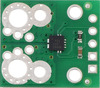
CT220BMV-HS5 Contactless Current Sensor Carrier ±1.5mT/15G. |
|---|
This carrier board features the CT220BMV-HS5, which has a magnetic field range of ±1.5 mT (±15 G). Its output sensitivity is 1500 mV/mT when VDD is 5 V (or 990 mV/mT when VDD is 3.3 V). This version can be visually distinguished from the other versions by a marking that starts with AC printed on the sensor IC, as shown in the picture above (the silkscreen also has a blank white box that can be used for adding customized identifying markings).
| IC Part Number | Range | Supply Voltage | Sensitivity @ 5V | Zero Point @ 5V | Size |
|---|---|---|---|---|---|
| CT220BMV-HS5 | ±1.5 mT (bidirectional) | 2.7 V to 5.5 V | 1500 mV/mT | 2.5 V | 0.4″×0.62″ |
The sensor’s current range and current sensitivity depend on its distance from the conductor, along with other parameters like the conductor’s geometry and angle relative to the board. When the board is tied to a round wire as pictured below, the overall diameter of the wire (with insulation) will be the main factor, and these graphs can help you estimate the sensor’s range and sensitivity for wires of different thicknesses. However, you should calibrate the sensor in your particular setup for best results (see Converting the sensor output into a current reading below).
 |
 |
Using the sensor
This CT220 carrier board is designed to measure a current running parallel to the long axis of the board, which generates a magnetic field forming concentric circles around the current conductor. Two pairs of slots along the sides of the board provide a good way to attach the board to a wire with small zip ties (cable ties) or similar fasteners.
|
|


The sensor requires a supply voltage of 2.7 V to 5.5 V to be connected across VDD and GND. The sensor outputs a ratiometric analog voltage on OUT that is centered at VDD/2 and changes according to the magnetic field it senses.
When measuring current in a conductor on the same side of the board as the sensor (over the IC, such as with the sensor tied to a wire as shown above), current flowing in the direction of the red arrow in the picture above increases the output voltage, while current flowing in the opposite direction decreases the output voltage. If the conductor is instead on the opposite side of the board from the sensor (under the IC), these directions are flipped.
The FLAG pin is normally high and drives low when the magnetic field is above 90% or below 10% of the full field range.
These connections can be made through the board’s JST SH-style 4-pin connector, which works with our 4-pin JST SH-style cables, or with a set of through-holes that are spaced with a 0.1″ (2.54 mm) pitch and compatible with 0.1″ male headers and solderless breadboards.
 |
Converting the sensor output into a current reading
To get accurate current readings from the CT220, it is necessary to calibrate it in your application setup. A simple way to do this involves the following two steps:
- Calibrate the sensor’s offset b by recording its output voltage with zero flowing current.
- Apply a known current A1 to the conductor and measure the sensor’s output voltage V1. This lets you calculate the sensor’s current gain (sensitivity) a with the equation: ``a = \frac {V_1 – b} {A_1}``
Then, given a voltage VOUT measured from the sensor, you can calculate the corresponding current with the gain a and offset b:
``\text {Current} = \frac {V_\text {OUT} – b} {a}``
To illustrate this with an example, let’s say you measure your sensor with no current flowing in the wire and get 2.5 V. Next, you put 10 A through your wire and measure the sensor voltage again, this time getting 2.8 V. That means the output voltage changed by 0.3 V for 10 A, so the sensitivity is 0.03 V/A, or 30 mV per A.
For better accuracy in bidirectional current applications, Allegro recommends a slightly more thorough calibration procedure that involves applying a known current in both directions; see the CT220 datasheet (2MB pdf) for details.
Schematic and dimension diagrams
 |
Schematic diagram of the CT220 Contactless Current Sensor Carrier. |
|---|
The dimension diagram is available as a downloadable PDF (301k pdf).
Comparison of the Pololu current sensor carriers
We have a variety of current sensors available with different ranges, sensitivities, and features. The table below summarizes our selection of active and preferred options:
 |
 |
 |
 |
 |
 |
 |
 |
 |
 |
|
|---|---|---|---|---|---|---|---|---|---|---|
| CT220 Contactless Current Sensor Carriers |
ACS3704x Current Sensor Micro Carriers |
ACS3704x Current Sensor Compact Carriers |
ACS711 Current Sensor Carriers |
ACS71240 Current Sensor Carriers |
ACS724 Current Sensor Carriers |
ACS37100 TMR Current Sensor Compact Carriers |
ACS37030LZ Current Sensor Compact Carriers |
ACS37030MY Current Sensor Compact Carriers |
CT432/CT433 TMR Current Sensor Compact Carriers |
|
| Allegro Sensor | CT220xMV-HS5 | ACS3704x | ACS711KEXT | ACS71240 | ACS724LLCTR | ACS37100 | ACS37030LLZ | ACS37030LMY | CT432/CT433 | |
| Sensing technology | XtremeSense™ TMR (tunneling magnetoresistance) |
Hall effect | Hall effect | Hall effect | Hall effect | XtremeSense™ TMR (tunneling magnetoresistance) |
Hall effect + inductive coil | XtremeSense™ TMR (tunneling magnetoresistance) |
||
| Logic voltage range | 2.7–5.5 V | 3.3V versions: 3.0–3.6 V 5V versions: 4.75–5.5 V |
3.0–5.5 V | 3.3V ver: 3.0–3.6 V 5V ver: 4.5–5.5 V |
4.5–5.5 V | 3.0–3.6 V | 3.0–3.6 V | 3.3V ver: 3.0–3.6 V 5V ver: 4.75–5.5 V |
||
| Family current range | 10–800 A | 10–30 A | 15.5–31 A | 10–50 A | 2.5–50 A | 25–50 A | 20–65 A | 20–70 A | ||
| Range/sensitivity of individual versions | (2) ±1.5 mT / 1500 mV/mT ±15 mT / 150 mV/mT |
ACS37041: 3.3V Bidirectional: ±10 A / 132 mV/A ±30 A / 44 mV/A 5V Bidirectional: ±10 A / 200 mV/A ±30 A / 66.7 mV/A ACS37042: 3.3V Bidirectional: ±10 A / 132 mV/A ±30 A / 44 mV/A 5V Bidirectional: ±10 A / 200 mV/A ±30 A / 66.7 mV/A |
ACS37041: 3.3V Bidirectional: ±10 A / 132 mV/A ±30 A / 44 mV/A 5V Bidirectional: ±10 A / 200 mV/A ±30 A / 66.7 mV/A ACS37042: 3.3V Bidirectional: ±10 A / 132 mV/A ±30 A / 44 mV/A 5V Bidirectional: ±10 A / 200 mV/A ±30 A / 66.7 mV/A |
Bidirectional:(1) ±15.5 A / 90 mV/A ±31 A / 45 mV/A |
3.3V Bidirectional: ±10 A / 132 mV/A ±30 A / 44 mV/A ±50 A / 26.4 mV/A 5V Bidirectional: ±10 A / 200 mV/A ±30 A / 66 mV/A ±50 A / 40 mV/A 5V Unidirectional: 0–50 A / 80 mv/A |
5V Bidirectional:(2) ±2.5 A / 800 mV/A ±5 A / 400 mV/A ±10 A / 200 mV/A ±20 A / 100 mV/A ±30 A / 66 mV/A ±50 A / 40 mV/A 5V Unidirectional:(2) 0–5 A / 800 mv/A 0–10 A / 400 mv/A 0–20 A / 200 mv/A 0–30 A / 133 mV/A |
3.3V Bidirectional: ±25 A / 52.8 mV/A ±50 A / 26.4 mV/A |
3.3V Bidirectional: ±20 A / 66 mV/A ±40 A / 33 mV/A ±65 A / 20.3 mV/A |
3.3V Bidirectional: ±20 A / 66 mV/A ±40 A / 33 mV/A ±65 A / 20.3 mV/A |
3.3V Bidirectional: ±20 A / 50 mV/A ±30 A / 33.3 mV/A ±50 A / 20 mV/A ±70 A / 14.3 mV/A 3.3V Unidirectional: 0–20 A / 100 mv/A 0–30 A / 66.7 mv/A 0–50 A / 40 mv/A 0–65 A / 30.8 mv/A 5V Bidirectional: ±20 A / 100 mV/A ±30 A / 66.7 mV/A ±50 A / 40 mV/A ±65 A / 30.8 mV/A 5V Unidirectional: 0–20 A / 200 mv/A 0–30 A / 133.3 mv/A 0–50 A / 80 mv/A 0–70 A / 57.1 mv/A |
| Max bandwidth | 30 kHz | 150 kHz | 100 kHz | 120 kHz | 120 kHz(3) | 10 MHz | 5 MHz | 1 MHz | ||
| IC current path resistance | N/A (contactless) | 1.6 mΩ | 0.6 mΩ | 0.6 mΩ | 0.6 mΩ | 1.2 mΩ | 0.7 mΩ | 0.9 mΩ | 1 mΩ | |
| IC isolation rating(6) | N/A (contactless) | ACS37041: 100 VRMS ACS37042: 285 VRMS |
100 Vpk | 100 Vpk | 297 VRMS | 1097 VRMS | 840 VRMS | 1000 VRMS | 1100 VRMS | |
| Minimum PCB creepage(7) | N/A (contactless) | ACS37041: 1.6 mm ACS37042: 2.0 mm |
ACS37041: 1.6 mm ACS37042: 3.0 mm |
0.75 mm | 0.75 mm | 1.1 mm | 9.3 mm | 4.1 mm | 11.7 mm | 8 mm |
| PCB | N/A (contactless) | 2 layers, 1-oz copper |
2 layers, 2-oz copper |
2 layers, 2-oz copper |
2 layers, 2-oz copper |
2 layers, 2- or 4-oz copper(4) |
2 layers, 2-oz copper |
2 layers, 2-oz copper |
2 or 4 layers(5), 2-oz copper |
|
| Size | 0.4″ × 0.62″ | 0.3″ × 0.4″ | 0.7″ × 0.8″ | 0.7″ × 0.8″ | 0.7″ × 0.8″ | 0.7″ × 0.8″ | 0.8″ × 1.1″ | 0.7″ × 0.8″ | 0.8″ × 1.1″ | 0.8″ × 1.1″ |
| Overcurrent fault output |
(configurable threshold) | |||||||||
| Common-mode field rejection | ||||||||||
| Nonratiometric output | ||||||||||
| 1-piece price | $4.95 | $4.15 – $4.69 | $4.45 – $4.99 | $4.85 | $5.25 | $9.95 – $11.49 | $14.95 | $8.95 | $12.95 | $12.95 |
Note 1: Sensitivity when Vcc = 3.3 V; actual sensitivity is ratiometric (i.e. it is proportional to Vcc).
Note 2: Sensitivity when Vcc = 5 V; actual sensitivity is ratiometric (i.e. it is proportional to Vcc).
Note 3: Bandwidth can be reduced by adding a filter capacitor.
Note 4: 50A version of this carrier uses 4-oz copper PCB; all other versions of this carrier use 2-oz copper.
Note 5: 50A and higher versions of this carrier use a 4-layer PCB; all other versions of this carrier use a 2-layer PCB.
Note 6: IC component rating per manufacturer datasheet.
Note 7: Minimum creepage along PCB surface based on layout design only. Other creepage distances, e.g. along the body of the component, may be lower.
|
 |
|
 |
|
 |
|
 |
 |
 |
 |
 |
 |
 |
|
|---|---|---|---|---|---|---|---|---|---|---|---|---|---|---|
| ACS37100 Current Sensor Compact Carriers |
ACS37100 Current Sensor Large Carriers |
ACS37030LZ Current Sensor Compact Carriers |
ACS37030LZ Current Sensor Large Carriers |
ACS37030MY Current Sensor Compact Carriers |
ACS37030MY Current Sensor Large Carriers |
CT432/CT433 TMR Current Sensor Compact Carriers |
CT432/CT433 TMR Current Sensor Large Carriers |
ACS72981 Current Sensor Compact Carriers |
ACS72981 Current Sensor Large Carriers |
ACS37220 Current Sensor Compact Carriers |
ACS37220 Current Sensor Large Carriers |
ACS37200 Current Sensor Compact Carriers |
ACS37200 Current Sensor Large Carriers |
|
| Allegro Sensor | ACS37100 | ACS37030LLZ | ACS37030LMY | CT432/CT433 | ACS72981xLR | ACS37220 | ACS37200 | |||||||
| Sensing technology | XtremeSense™ TMR (tunneling magnetoresistance) |
Hall effect + inductive coil | XtremeSense™ TMR (tunneling magnetoresistance) |
Hall effect | Hall effect | |||||||||
| Logic voltage range | 3.0–3.6 V | 3.0–3.6 V | 3.3V versions: 3.0–3.6 V 5V versions: 4.75–5.5 V |
3.3V versions: 3.0–3.6 V 5V versions: 4.5–5.5 V |
3.3V versions: 3.15–3.45 V 5V versions: 4.5–5.5 V |
|||||||||
| Family current range | 25–50 A | 20–65 A | 20–70 A | 50–200 A | 100–200 A | |||||||||
| Range/sensitivity of individual versions | 3.3V Bidirectional: ±25 A / 52.8 mV/A ±50 A / 26.4 mV/A |
3.3V Bidirectional: ±25 A / 52.8 mV/A ±50 A / 26.4 mV/A |
3.3V Bidirectional: ±20 A / 66 mV/A ±40 A / 33 mV/A ±65 A / 20.3 mV/A |
3.3V Bidirectional: ±40 A / 33 mV/A ±65 A / 20.3 mV/A |
3.3V Bidirectional: ±25 A / 52.8 mV/A ±40 A / 33 mV/A ±65 A / 20.3 mV/A |
3.3V Bidirectional: ±40 A / 33 mV/A ±65 A / 20.3 mV/A |
3.3V Bidirectional: ±20 A / 50 mV/A ±30 A / 33.3 mV/A ±50 A / 20 mV/A ±70 A / 14.3 mV/A 3.3V Unidirectional: 0–20 A / 100 mv/A 0–30 A / 66.7 mv/A 0–50 A / 40 mv/A 0–65 A / 30.8 mv/A 5V Bidirectional: ±20 A / 100 mV/A ±30 A / 66.7 mV/A ±50 A / 40 mV/A ±65 A / 30.8 mV/A 5V Unidirectional: 0–20 A / 200 mv/A 0–30 A / 133.3 mv/A 0–50 A / 80 mv/A 0–70 A / 57.1 mv/A |
3.3V Bidirectional: ±50 A / 20 mV/A ±70 A / 14.3 mV/A 3.3V Unidirectional: 0–50 A / 40 mv/A 0–65 A / 30.8 mv/A 5V Bidirectional: ±50 A / 40 mV/A ±65 A / 30.8 mV/A 5V Unidirectional: 0–50 A / 80 mv/A 0–70 A / 57.1 mv/A |
3.3V Bidirectional:(1) ±50 A / 26.4 mV/A ±100 A / 13.2 mV/A ±150 A / 8.8 mV/A ±200 A / 6.6 mV/A 3.3V Unidirectional:(1) 0–50 A / 52.8 mv/A 0–100 A / 26.4 mv/A 0–150 A / 17.6 mv/A 0–200 A / 13.2 mv/A 5V Bidirectional:(2) ±50 A / 40 mV/A ±100 A / 20 mV/A ±150 A / 13.3 mV/A ±200 A / 10 mV/A 5V Unidirectional:(2) 0–50 A / 80 mv/A 0–100 A / 40 mv/A 0–150 A / 26.7 mv/A |
3.3V Bidirectional:(1) ±50 A / 26.4 mV/A ±100 A / 13.2 mV/A ±150 A / 8.8 mV/A ±200 A / 6.6 mV/A 3.3V Unidirectional:(1) 0–50 A / 52.8 mv/A 0–100 A / 26.4 mv/A 0–150 A / 17.6 mv/A 0–200 A / 13.2 mv/A 5V Bidirectional:(2) ±50 A / 40 mV/A ±100 A / 20 mV/A ±150 A / 13.3 mV/A ±200 A / 10 mV/A 5V Unidirectional:(2) 0–50 A / 80 mv/A 0–100 A / 40 mv/A 0–150 A / 26.7 mv/A |
3.3V Bidirectional: ±100 A / 13.2 mV/A ±150 A / 8.8 mV/A 5V Bidirectional: ±100 A / 20 mV/A ±150 A / 13.3 mV/A ±200 A / 10 mV/A |
3.3V Bidirectional: ±100 A / 13.2 mV/A ±150 A / 8.8 mV/A 5V Bidirectional: ±100 A / 20 mV/A ±150 A / 13.3 mV/A ±200 A / 10 mV/A |
3.3V Bidirectional: ±200 A / 6.6 mV/A 5V Bidirectional: ±100 A / 20 mV/A |
3.3V Bidirectional: ±200 A / 6.6 mV/A 5V Bidirectional: ±100 A / 20 mV/A |
| Max bandwidth | 10 MHz | 5 MHz | 1 MHz | 250 kHz | 150 kHz | |||||||||
| IC current path resistance | 1.2 mΩ | 0.7 mΩ | 0.9 mΩ | 1 mΩ | 0.2 mΩ | 0.1 mΩ | 0.05 mΩ | |||||||
| IC isolation rating(4) | 1097 VRMS | 840 VRMS | 1000 VRMS | 1100 VRMS | 100 Vpk | 100 VRMS | 1097 VRMS | |||||||
| Minimum PCB creepage(5) | 9.3 mm | 10.1 mm | 4.1 mm | 11.7 mm | 11.9 mm | 8 mm | 1.1 mm | 1.0 mm | 10.1 mm | 10.4 mm | ||||
| PCB | 2 layers, 2-oz copper |
6 layers, 2-oz copper |
2 layers, 2-oz copper |
6 layers, 2-oz copper |
2 layers, 2-oz copper |
6 layers, 2-oz copper |
2 or 4 layers(3), 2-oz copper |
6 layers, 2-oz copper |
6 layers, 2-oz copper |
6 layers, 2-oz copper |
2 layers, 2-oz copper |
6 layers, 2-oz copper |
2 layers, 2-oz copper |
6 layers, 2-oz copper |
| Size | 0.8″ × 1.1″ | 1.4″ × 1.2″ | 0.7″ × 0.8″ | 1.4″ × 1.2″ | 0.8″ × 1.1″ | 1.4″ × 1.2″ | 0.8″ × 1.1″ | 1.4″ × 1.2″ | 0.7″ × 0.8″ | 1.4″ × 1.2″ | 0.7″ × 0.8″ | 1.4″ × 1.2″ | 0.8″ × 1.1″ | 1.4″ × 1.2″ |
| Overcurrent fault output |
(configurable threshold) | (configurable threshold) | ||||||||||||
| Common-mode field rejection | ||||||||||||||
| Nonratiometric output | ||||||||||||||
| 1-piece price | $14.95 | $19.95 | $8.95 | $11.95 | $12.95 | $17.95 | $12.95 | $16.95 | $13.95 | $16.95 | $6.95 | $10.95 | $19.95 | $24.95 |
Note 1: Sensitivity when Vcc = 3.3 V; actual sensitivity is ratiometric (i.e. it is proportional to Vcc).
Note 2: Sensitivity when Vcc = 5 V; actual sensitivity is ratiometric (i.e. it is proportional to Vcc).
Note 3: 50A and higher versions of this carrier use a 4-layer PCB; all other versions of this carrier use a 2-layer PCB.
Note 4: IC component rating per manufacturer datasheet.
Note 5: Minimum creepage along PCB surface based on layout design only. Other creepage distances, e.g. along the body of the component, may be lower.
You can also use the following selection box to see these options sorted by current range:
Alternatives available with variations in these parameter(s): current range Select variant…
Related products


Related categories


Home | Forum | Blog | Support | Ordering Information | Lists | Distributors | BIG Order Form | About | Contact
© 2001–2026 Pololu Corporation
