Pololu Blog » User Profile: Emily » Posts by Emily »
Posts by Emily (Page 6)
You are currently viewing a selection of posts from the Pololu Blog. You can also view all the posts.
Popular tags: community projects new products raspberry pi arduino more…
Video: Installing Multi-Hub Wheels
This short video shows how to install one of our multi-hub wheels on a motor. These wheels are currently available as an 80×10mm black pair and an 80×10mm white pair. They are cool because they include a set of interchangeable collets that can be inserted into the wheel to firmly grab four different shaft types: 3mm D, 3mm round, 4mm D, and 4mm round. For more information about what went into designing these wheels, check out Jan’s blog post from when they were initially released.
Our introductory special for these wheels is still available. Use coupon code MULTIHUBINTRO and get 33% off on up to three sets.

Related products


New linear actuators and Jrk settings files
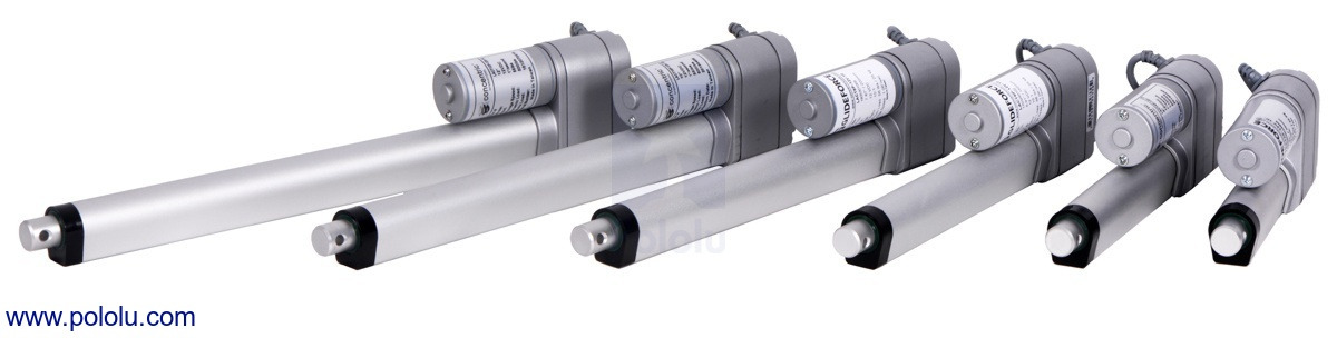 |
We’ve expanded our line of Glideforce Light-Duty Linear Actuators to now include options with a 10:1 gear ratio. As you might know if you are a long time customer, we’ve carried our light-duty actuators in 20:1 and 5:1 gear ratios for many years. The 20:1 actuators have nice load capabilities, but they’re kind of slow. The 5:1 actuators are speedy, but they can’t push around the larger loads that the 20:1 actuators can. These new 10:1 actuators fall in the middle, offering a great blend of force and speed.
We carry these new actuators in stroke lengths ranging from 2–12 inches and in versions with and without feedback, bringing our total line of light-duty actuators to 28 options.
| Actuator Type |
Max Dynamic Load |
No-Load Speed @ 12 V |
Max-Load Speed @ 12 V |
Current Draw @ 12 V |
Nominal Stroke Length |
With Feedback |
Without Feedback |
|---|---|---|---|---|---|---|---|
| Light-Duty (LD) 5:1 |
15 kgf [34 lbs] |
4.4 cm/s [1.7″/s] |
3.6 cm/s [1.4″/s] |
1.2 A – 3.2 A |
4″ | LACT4P-12V-05 | LACT4-12V-05 |
| 12″ | LACT12P-12V-05 | LACT12-12V-05 | |||||
| Light-Duty (LD) 10:1 |
25 kgf [55 lbs] |
2.8 cm/s [1.1″/s] |
2.3 cm/s [0.9″/s] |
1.2 A – 3.2 A |
2″ | LACT2P-12V-10 | LACT2-12V-10 |
| 4″ | LACT4P-12V-10 | LACT4-12V-10 | |||||
| 6″ | LACT6P-12V-10 | LACT6-12V-10 | |||||
| 8″ | LACT8P-12V-10 | LACT8-12V-10 | |||||
| 10″ | LACT10P-12V-10 | LACT10-12V-10 | |||||
| 12″ | LACT12P-12V-10 | LACT12-12V-10 | |||||
| Light-Duty (LD) 20:1 |
50 kgf [110 lbs] |
1.5 cm/s [0.57″/s] |
1.2 cm/s [0.48″/s] |
1.2 A – 3.2 A |
2″ | LACT2P-12V-20 | LACT2-12V-20 |
| 4″ | LACT4P-12V-20 | LACT4-12V-20 | |||||
| 6″ | LACT6P-12V-20 | LACT6-12V-20 | |||||
| 8″ | LACT8P-12V-20 | LACT8-12V-20 | |||||
| 10″ | LACT10P-12V-20 | LACT10-12V-20 | |||||
| 12″ | LACT12P-12V-20 | LACT12-12V-20 | |||||
For actuators with feedback, a built-in potentiometer is linked to the shaft position allowing for precise control of the actuator’s extension. Our line of Jrk G2 Motor Controllers with Feedback are a great solution for use with any of our linear actuators with feedback, and our most affordable option, the Jrk G2 21v3, is a great choice for use with our light-duty actuators specifically.
In separate but related news, we’ve also either created or updated Jrk settings files for all our linear actuators with feedback for use with our Jrk G2s:
- Light-duty actuators with the 5:1 gear ratio: Jrk 21v3 settings file for use with LACTxP-12V-5 (2k txt)
- Light-duty actuators with 10:1 or 20:1 gear ratios: Jrk 21v3 settings file for use with LACTxP-12V-10 or LACTxP-12V-20 (2k txt)
- Medium-duty actuators: Jrk 24v13 settings for MD linear actuators (2k txt)
- Industrial-duty actuators: Jrk 24v21 settings for ID linear actuators (2k txt)
These settings files can be opened in the Jrk configuration utility and then uploaded to your Jrk G2 motor controller. Please make sure to follow the detailed instructions on your actuator’s product page.
So what does one of these settings files do for you? The Jrks use a PID control loop to control the position of a motor based on feedback from that motor. PID stands for proportional, integral, and derivative, and for a control loop to work well, the PID coefficients must be tuned for the specific system they are being used in. The Jrk uses the coefficients for those terms along with the along with the difference between the motor’s actual position and its target position to calculate what the power to the motor should be. The details of this calculation are discussed in the Jrk’s user’s guide. Tuning the PID coefficients so your motor goes where you want it to can sometimes be difficult. The Jrk settings files provide a set of parameters that should work well for most uses of the linear actuators. Some systems might require more fine tuning, but even in those cases, the files should provide a good starting point.
I created these files by first starting with the default settings for the Jrk motor controller. I left the settings on the Motor, Errors, and Advanced tabs of the Jrk configuration utility on their defaults (with the exception of one of the files for the light-duty actuators having the motor direction reversed). On the input tab, I also left the input mode in Serial so you can control the linear actuator directly from the software. On the feedback tab, I set the feedback mode to analog voltage so the Jrk can read the potentiometer wiper of the linear actuator. To get the feedback values, I connected an actuator to the Jrk and ran the feedback setup wizard. (You might need to rerun this wizard for the specific actuator you have connected to your Jrk. The instructions on the actuators’ product pages go into more detail about this.)
Once all that was done, I configured the PID settings and worked out the PID coefficients by testing each type of actuator with the Jrks. We wanted to provide files that worked generally well across all the stroke length options for each type of actuator, so a lot of actuators were tested to come up with coefficients that worked well for all of them.
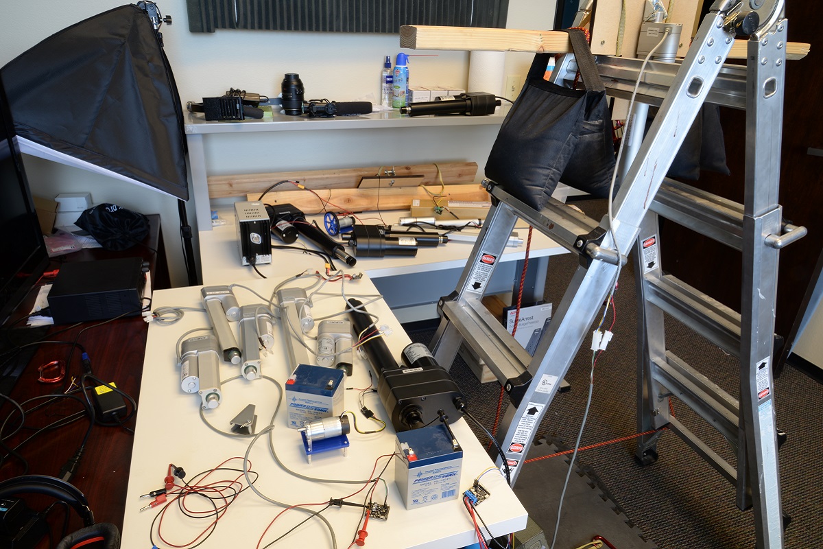 |
Many of the actuators used for creating Jrk settings files (can you find all 12?). |
|---|
I set the proportional and derivative terms first, selecting terms that allowed the actuators to move at their highest speeds but not overshoot their target position. In general, you can get fairly good control over the actuator just using the proportional and derivative terms. In fact, if you are just testing your motor without a load, it might seem like you don’t need an integral term at all. However, there are situations where the control system can get stuck without moving all the way to its target. The controller will continue to apply power to get the actuator to the set position, but it won’t be enough to actually move the actuator. This can be fixed using the integral term of the PID loop. The error will add up over time and eventually get big enough to get things moving again. I was able to test this with the light-duty actuators using the setup below:
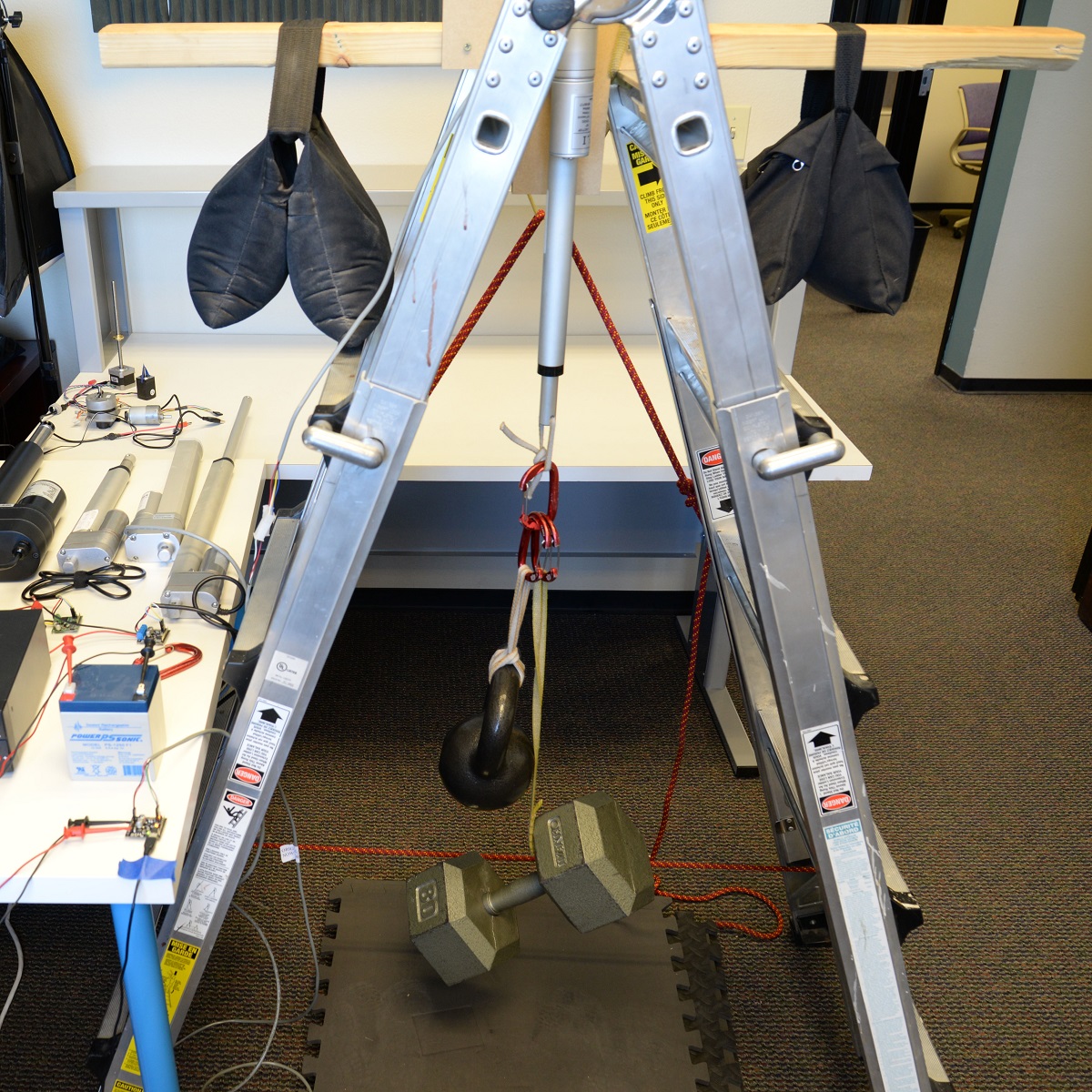 |
Testing Jrk settings with a load. |
|---|
That’s one of our 20:1 light-duty actuators lifting 105 lbs (5 lbs less than its max dynamic load rating). Once I had a large enough load on the actuator, I could see that without an integral term set, the actuator would stall just short of its target position, continuing to apply power but not getting anywhere. Once the integral term was added, the Jrk was able to move it that last little bit to the target.
Unfortunately, I wasn’t able to perform the same test with our medium- and heavy-duty actuators; my makeshift testing rig couldn’t support a load high enough to produce the steady state error issue. However, I did add a little bit of an integral term to the files for those actuators anyway, making sure that doing so didn’t have an obvious negative effect on their performance.
If you want to learn some more about PID control, I found this video and its follow up from Brian Douglas’s channel on YouTube a helpful starting point.
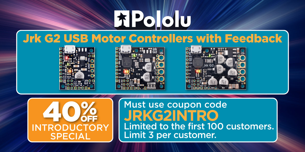
One last note: the intro coupon for our Jrk G2 controllers still has some uses left. Add coupon code JRKG2INTRO to your cart and get up to three Jrk G2 motor controllers for 40% off!
Related products


Video: How to Install Terminal Blocks
On Monday, after receiving a photo of some wonky-looking terminal blocks, our tech support team mentioned to me that we get a good amount of photos from customers needing help with their products that have their terminal blocks installed incorrectly. They either aren’t stacked together properly, are inserted into the wrong holes on the boards, or they’re soldered incorrectly. I tried to make some recreations of the problems we see most often so you can see what I’m talking about:
|
|
|

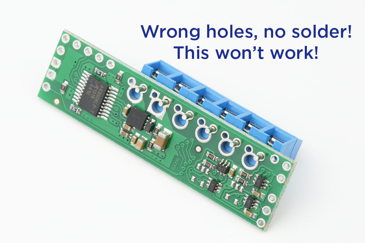
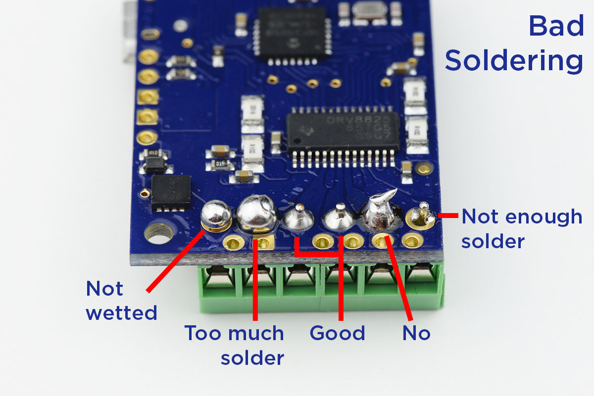
So at the request of our support team, I made this video that goes over how terminal blocks should be installed:
Related products


Video: Overview of the Jrk G2 Motor Controllers with Feedback
In our last blog post, we announced the release of our second generation of Jrk Motor Controllers with Feedback. If that announcement wasn’t enough to get you excited about the Jrks, here’s a short video to give you a taste of what the Jrks can do:
You totally want one now, right? Well lucky for you, our special introductory coupon is still valid. The first 100 customers to use coupon code JRKG2INTRO can get 40% off up to three units. (Click to add the coupon code to your cart.)

Video: Getting Started with the Tic Stepper Motor Controllers
As I showed in my last post a few weeks ago, our Tic stepper motor controllers offer six different control interfaces so you can add stepper motors to a variety of projects. Getting started with the Tics is easy. This new video tutorial steps (see what I did there?) you through getting your stepper motor running with our Tic controllers:
As I was making this video, I realized one of the coolest things about the Tic is how quickly you can work out the capabilities of your stepper motor. Even if you’re comfortable using one of our stepper motor drivers along with a microcontroller, using the Tics makes adjusting settings like current limits, step rates, speed, and acceleration as quick as a click of the button, and you can control your motor directly from the software to make sure it’s behaving how you would like. So you might want to keep an extra Tic around for that purpose, just as a stepper motor tester.
Right now you can still purchase our newest Tic at a special introductory price of just $15.53 using the coupon code T500INTRO! (Click to add the coupon code to your cart.) We also cover shipping in the US! Note that this introductory offer applies only to the units without connectors soldered in.

Related products


Video: Introducing the Tic Stepper Motor Controllers
Our Tic Stepper Motor Controllers make basic control of stepper motors easy. This quick video shows you all the control interfaces you can use with our Tics to add stepper motors to your projects:
Making this video was actually the first time I’ve had a chance to play around with the Tics, and I was pleasantly surprised at how quickly I was able to set up the Tic with each interface option. Once I had everything connected, it only took a few minutes using the control software to get things moving for each setup.
This video also gives a sneak peek of our new Tic T500 (the red Tics in the opening shot). Like our new stepper motor drivers, the T500s are based on the MPS MP6500 bipolar stepper motor driver. Keep an eye on this blog for their release in the coming weeks.
Related products
LED strip code used in Pololu Christmas video
We added the code we used for the LEDs in our Christmas video last week to our GitHub page. Ben cleaned it up a bit and added lots of comments, so we hope it’s helpful if you want to use it as a base to write some awesome sequences for your own LED strips.
In case you missed the video, here it is again:
A Pololu Christmas Story (with LEDs!)
Merry Christmas! We got some new LED strips in a week or so ago that are based on the WS2812B. I was pretty excited to play around with them, so I decided I would decorate Ben’s house and make him film this video with me. (I know. I should have decorated my own house, but I live far from the office… and don’t have a wife.)
We should have the code we used for the LEDs available on our github page in a couple of days.
Free Elektor magazine December 2013
 |
Get a FREE copy of Elektor magazine’s December issue with your order while supplies last. To get your free issue, enter the coupon code ELEKTOR1213 into your shopping cart. The magazine will add 5 ounces to the package weight when calculating your shipping options.
For other issues and more information, see our Free Elektor Magazine Offers page. All issues are now available for shipping worldwide!
Related products

Video: Introducing the Zumo Robot for Arduino
Our Zumo Robot is a great platform for getting into robotics with your Arduino. The Zumo was designed with Mini Sumo competitions in mind, but that’s not the only thing you can do with it. This video gives an overview of the Zumo’s features and some ideas on what you can do to make it your own.


Home | Forum | Blog | Support | Ordering Information | Wish Lists | Distributors | BIG Order Form | About | Contact
© 2001–2024 Pololu Corporation


