Pololu Blog »
New linear actuators and Jrk settings files
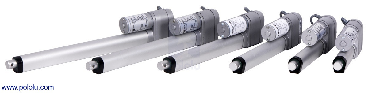 |
We’ve expanded our line of Glideforce Light-Duty Linear Actuators to now include options with a 10:1 gear ratio. As you might know if you are a long time customer, we’ve carried our light-duty actuators in 20:1 and 5:1 gear ratios for many years. The 20:1 actuators have nice load capabilities, but they’re kind of slow. The 5:1 actuators are speedy, but they can’t push around the larger loads that the 20:1 actuators can. These new 10:1 actuators fall in the middle, offering a great blend of force and speed.
We carry these new actuators in stroke lengths ranging from 2–12 inches and in versions with and without feedback, bringing our total line of light-duty actuators to 28 options.
| Actuator Type |
Max Dynamic Load |
No-Load Speed @ 12 V |
Max-Load Speed @ 12 V |
Current Draw @ 12 V |
Nominal Stroke Length |
With Feedback |
Without Feedback |
|---|---|---|---|---|---|---|---|
| Light-Duty (LD) 5:1 |
15 kgf [34 lbs] |
4.4 cm/s [1.7″/s] |
3.6 cm/s [1.4″/s] |
1.2 A – 3.2 A |
4″ | LACT4P-12V-05 | LACT4-12V-05 |
| 12″ | LACT12P-12V-05 | LACT12-12V-05 | |||||
| Light-Duty (LD) 10:1 |
25 kgf [55 lbs] |
2.8 cm/s [1.1″/s] |
2.3 cm/s [0.9″/s] |
1.2 A – 3.2 A |
2″ | LACT2P-12V-10 | LACT2-12V-10 |
| 4″ | LACT4P-12V-10 | LACT4-12V-10 | |||||
| 6″ | LACT6P-12V-10 | LACT6-12V-10 | |||||
| 8″ | LACT8P-12V-10 | LACT8-12V-10 | |||||
| 10″ | LACT10P-12V-10 | LACT10-12V-10 | |||||
| 12″ | LACT12P-12V-10 | LACT12-12V-10 | |||||
| Light-Duty (LD) 20:1 |
50 kgf [110 lbs] |
1.5 cm/s [0.57″/s] |
1.2 cm/s [0.48″/s] |
1.2 A – 3.2 A |
2″ | LACT2P-12V-20 | LACT2-12V-20 |
| 4″ | LACT4P-12V-20 | LACT4-12V-20 | |||||
| 6″ | LACT6P-12V-20 | LACT6-12V-20 | |||||
| 8″ | LACT8P-12V-20 | LACT8-12V-20 | |||||
| 10″ | LACT10P-12V-20 | LACT10-12V-20 | |||||
| 12″ | LACT12P-12V-20 | LACT12-12V-20 | |||||
For actuators with feedback, a built-in potentiometer is linked to the shaft position allowing for precise control of the actuator’s extension. Our line of Jrk G2 Motor Controllers with Feedback are a great solution for use with any of our linear actuators with feedback, and our most affordable option, the Jrk G2 21v3, is a great choice for use with our light-duty actuators specifically.
In separate but related news, we’ve also either created or updated Jrk settings files for all our linear actuators with feedback for use with our Jrk G2s:
- Light-duty actuators with the 5:1 gear ratio: Jrk 21v3 settings file for use with LACTxP-12V-5 (2k txt)
- Light-duty actuators with 10:1 or 20:1 gear ratios: Jrk 21v3 settings file for use with LACTxP-12V-10 or LACTxP-12V-20 (2k txt)
- Medium-duty actuators: Jrk 24v13 settings for MD linear actuators (2k txt)
- Industrial-duty actuators: Jrk 24v21 settings for ID linear actuators (2k txt)
These settings files can be opened in the Jrk configuration utility and then uploaded to your Jrk G2 motor controller. Please make sure to follow the detailed instructions on your actuator’s product page.
So what does one of these settings files do for you? The Jrks use a PID control loop to control the position of a motor based on feedback from that motor. PID stands for proportional, integral, and derivative, and for a control loop to work well, the PID coefficients must be tuned for the specific system they are being used in. The Jrk uses the coefficients for those terms along with the along with the difference between the motor’s actual position and its target position to calculate what the power to the motor should be. The details of this calculation are discussed in the Jrk’s user’s guide. Tuning the PID coefficients so your motor goes where you want it to can sometimes be difficult. The Jrk settings files provide a set of parameters that should work well for most uses of the linear actuators. Some systems might require more fine tuning, but even in those cases, the files should provide a good starting point.
I created these files by first starting with the default settings for the Jrk motor controller. I left the settings on the Motor, Errors, and Advanced tabs of the Jrk configuration utility on their defaults (with the exception of one of the files for the light-duty actuators having the motor direction reversed). On the input tab, I also left the input mode in Serial so you can control the linear actuator directly from the software. On the feedback tab, I set the feedback mode to analog voltage so the Jrk can read the potentiometer wiper of the linear actuator. To get the feedback values, I connected an actuator to the Jrk and ran the feedback setup wizard. (You might need to rerun this wizard for the specific actuator you have connected to your Jrk. The instructions on the actuators’ product pages go into more detail about this.)
Once all that was done, I configured the PID settings and worked out the PID coefficients by testing each type of actuator with the Jrks. We wanted to provide files that worked generally well across all the stroke length options for each type of actuator, so a lot of actuators were tested to come up with coefficients that worked well for all of them.
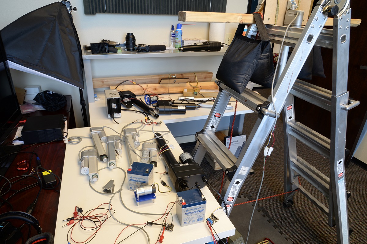 |
Many of the actuators used for creating Jrk settings files (can you find all 12?). |
|---|
I set the proportional and derivative terms first, selecting terms that allowed the actuators to move at their highest speeds but not overshoot their target position. In general, you can get fairly good control over the actuator just using the proportional and derivative terms. In fact, if you are just testing your motor without a load, it might seem like you don’t need an integral term at all. However, there are situations where the control system can get stuck without moving all the way to its target. The controller will continue to apply power to get the actuator to the set position, but it won’t be enough to actually move the actuator. This can be fixed using the integral term of the PID loop. The error will add up over time and eventually get big enough to get things moving again. I was able to test this with the light-duty actuators using the setup below:
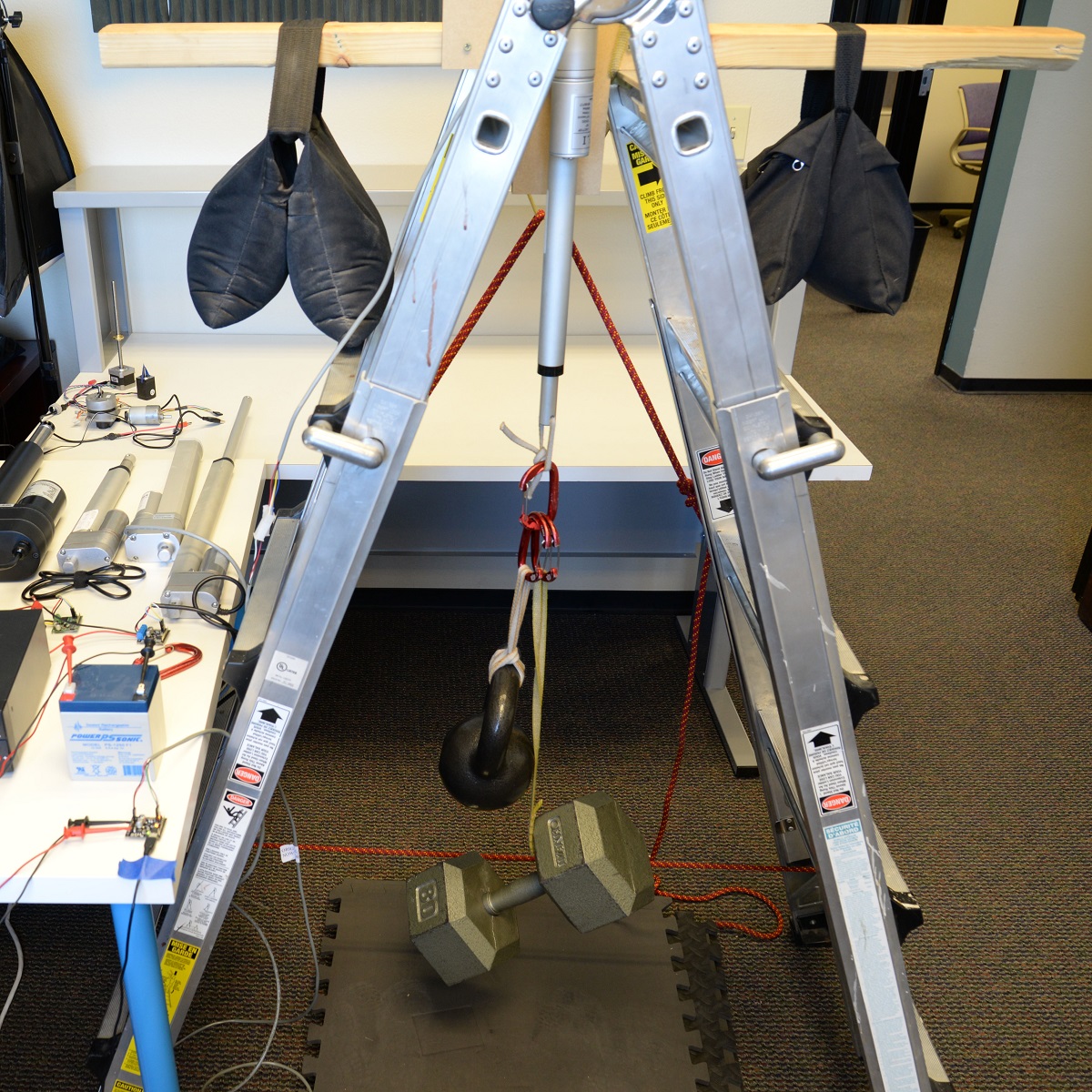 |
Testing Jrk settings with a load. |
|---|
That’s one of our 20:1 light-duty actuators lifting 105 lbs (5 lbs less than its max dynamic load rating). Once I had a large enough load on the actuator, I could see that without an integral term set, the actuator would stall just short of its target position, continuing to apply power but not getting anywhere. Once the integral term was added, the Jrk was able to move it that last little bit to the target.
Unfortunately, I wasn’t able to perform the same test with our medium- and heavy-duty actuators; my makeshift testing rig couldn’t support a load high enough to produce the steady state error issue. However, I did add a little bit of an integral term to the files for those actuators anyway, making sure that doing so didn’t have an obvious negative effect on their performance.
If you want to learn some more about PID control, I found this video and its follow up from Brian Douglas’s channel on YouTube a helpful starting point.
One last note: the intro coupon for our Jrk G2 controllers still has some uses left. Add coupon code JRKG2INTRO to your cart and get up to three Jrk G2 motor controllers for 40% off!

Related products


-
PyTic - Python interface for Pololu Tic Stepper Motor Controllers
- 7 August 2018Customer Daniel Castelli of the Allen Institute has released a Python package for interfacing with our Tic Stepper Motor Controllers. Currently, he...
-

New products: QTR HD sensor arrays by student engineering interns
- 10 August 2018Some of the Pololu summer 2018 student engineering interns posing with QTR HD circuit boards they designed. Hi everyone! My name is Matthew, and I...
0 comments
Post a comment


Home | Forum | Blog | Support | Ordering Information | Lists | Distributors | BIG Order Form | About | Contact
© 2001–2026 Pololu Corporation

