Pololu Blog »
Pololu Blog (Page 60)
Welcome to the Pololu Blog, where we provide updates about what we and our customers are doing and thinking about. This blog used to be Pololu president Jan Malášek’s Engage Your Brain blog; you can view just those posts here.
Popular tags: community projects new products raspberry pi arduino more…
Firetail UAV System
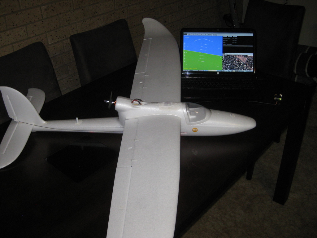 |
We mentioned it in passing in an earlier post, but we think that the Firetail UAV System deserves its own post. Since then, Firetail’s creator, Samuel Cowen, has continued to develop this open-source UAV autopilot system, posting regular updates on his blog and sharing his project on the Pololu forum.
Firetail is designed to be installed in any fixed-wing RC airframe and autonomously fly up to 512 waypoints. The system includes software for a ground control station, which allows users to see the location, speed, altitude, and orientation of the aircraft. Users at the station can also upload and download autopilot settings and plan flights using Google Maps.
To test Firetail, he built his own RC aircraft, which uses an Arduino Due to process signals from an RC receiver, and reads data from an AltIMU-10. Depending on how the user sets up the autopilot mode, the Firetail system either flies the craft, or simply allows the user to fly the craft while streaming telemetry data to the ground control station.
You can learn more about the Firetail system on its website.
 |
Related products


New product: Raspberry Pi Model B+
 |
The Raspberry Pi single-board computer has been around for a little over two years in its original Model A and Model B versions, and in that time, it’s become a very popular platform for electronics experimentation. With many of the same capabilities as a regular desktop or laptop PC, but at a small fraction of the size and cost, the Raspberry Pi offers features like network connectivity and significant processing power for robots and other electronics projects.
|
|
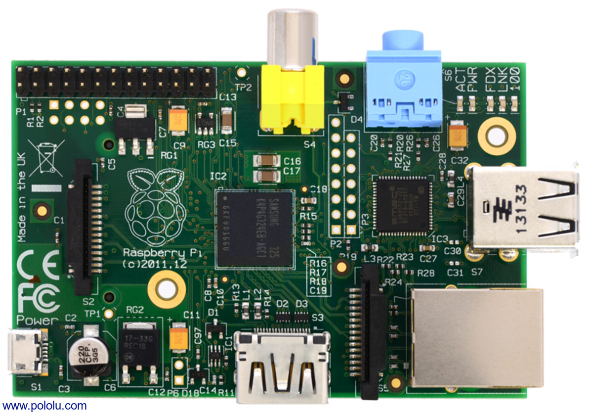
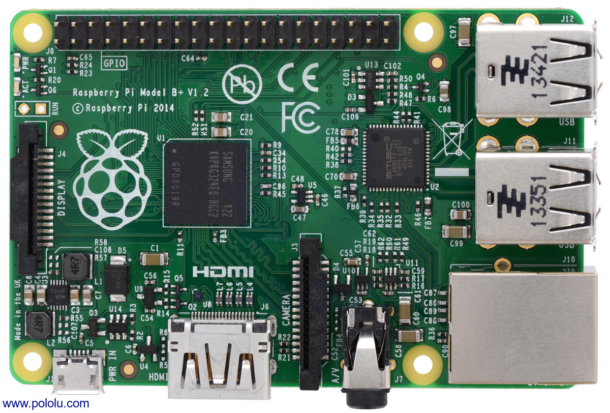
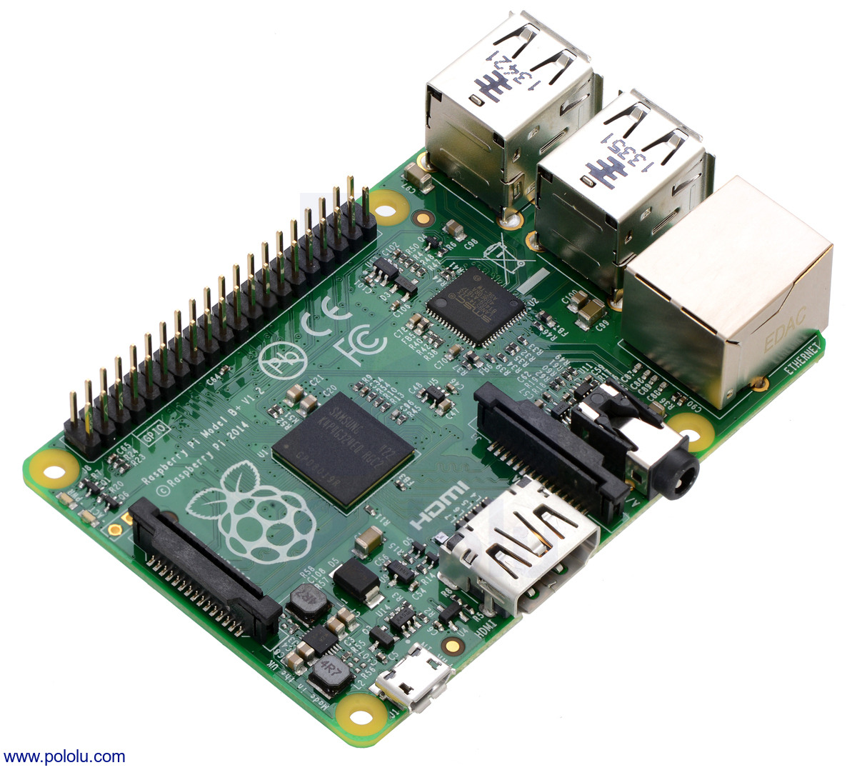
We’re now selling the new Raspberry Pi Model B+, which improves on the Model B in a number of ways:
- More GPIO pins are available on a 40-pin header; the Model B has a 26-pin GPIO header.
- The number of USB host ports has been doubled to four.
- Switching regulators lower the power consumption of the Model B+ by 0.5 W to 1 W compared to the Model B (which uses linear regulators), while audio is improved by a dedicated low-noise power supply.
- A much smaller microSD card socket replaces the previous full-size SD card socket.
- Audio and composite video output are combined on the 3.5 mm jack, and many of the connectors extend much less past the edge of the board (as does the inserted microSD card).
- Four mounting holes provide more flexibility in mounting the Model B+.
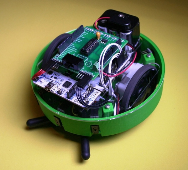
We’ve seen our customers build lots of cool projects with the Raspberry Pi, including a wirelessly-controlled Zumo robot with a video camera and a robotic ping-pong ball collector. We look forward to seeing what you’ll do with the Model B+!
Related products


Free magazines: July 2014 Circuit Cellar and July/August 2014 Elektor
|
|


Get FREE copies of Circuit Cellar magazine’s July issue and Elektor magazine’s July/August issue with your order, while supplies last. To get your free issues, enter the coupon codes CIRCUIT0714 and ELEKTOR0714 into your shopping cart. The Circuit Cellar magazine will add 6 ounces and the Elektor magazine will add 9 ounces to the package weight when calculating your shipping options.
For back issues and more information, see our free Circuit Cellar magazine offers and free Elektor magazine offers.


New products: CC3000 Wi-Fi breakout board and Arduino shield from Adafruit
 |
Adding wireless connectivity to an electronics project is a great way to enhance functionality and make it stand out. Our selection of wireless electronics includes radio frequency modules, such as the Wixel, and Bluetooth modules, like the BlueSMiRF Silver from SparkFun, but until recently, we did not carry a good solution to adding Wi-Fi to a project. That’s where the newest additions to our wireless selection come into play.
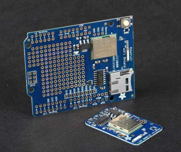
We are now carrying two CC3000 Wi-Fi module carrier boards from Adafruit: the CC3000 Wi-Fi Shield for Arduino and CC3000 Wi-Fi breakout board. The CC3000 is a self-contained wireless network processor with an SPI interface, so it is not limited to a fixed UART baud rate, and the Adafruit carrier boards include level shifters, so they should be simple to connect to almost any microcontroller. Adafruit’s CC3000 Arduino library and example sketches make them especially easy to use with an Arduino-compatible board.
|
|

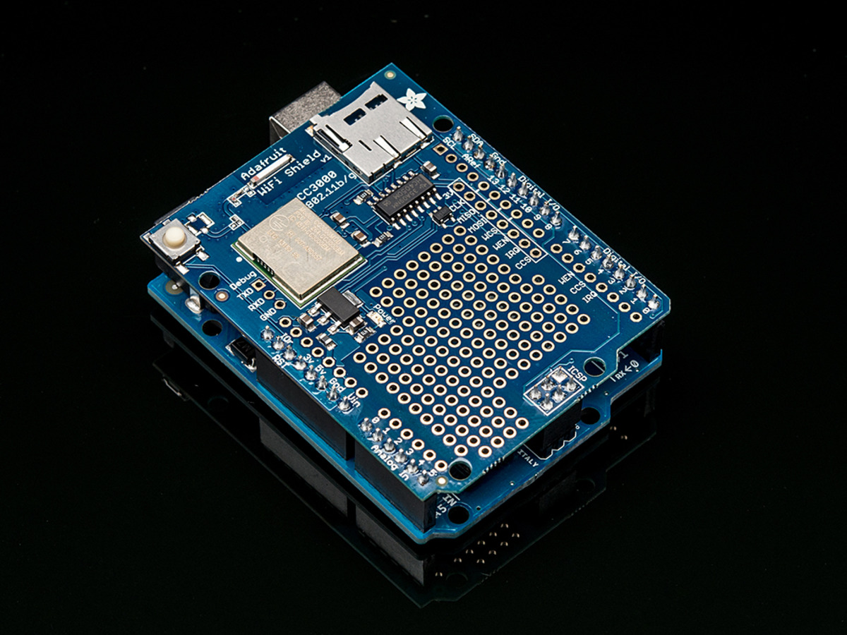
The CC3000 Wi-Fi Shield for Arduino offers a MicroSD card socket, a prototyping area for soldering extra circuitry, and a button for resetting the Arduino. The CC3000 Wi-Fi breakout board (v1.1) is much more compact and is also breadboard-compatible. Both products include an onboard ceramic antenna.
Related products


TwoPotatoe balancing robot
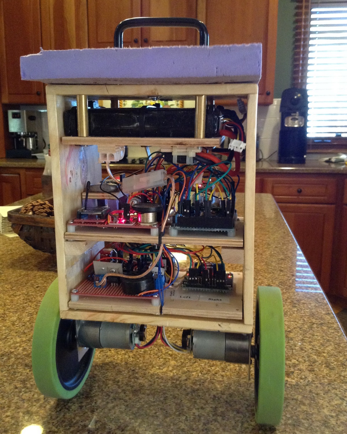 |
TwoPotatoe is a customer-built balancing robot that in its latest form uses an Arduino Mega to receive commands from a custom-made controller via XBees and a Wixel to wirelessly send telemetry to a PC. The robot uses feedback from a MinIMU-9 v3 IMU module’s accelerometer and gyro to maintain its balance, and it uses the MinIMU’s compass to navigate. The drive system consists of two 37D mm metal gearmotors with encoders controlled by a VNH3SP30 motor driver carrier.
You can see videos and read more about how TwoPotatoe works in the how it works section of its site.
10 December 2014 update: The old video of Twopotatoe has been replaced with a newer one. TwoPotatoe has also undergone a few changes: Arduino Due instead of the Arduino Mega, new motor controllers, new personality, etc. For more information about the changes and to see some new pictures, check out TwoPotatoe’s website.
Related products


New products: A-Star 32U4 Minis
 |
A few months ago, we released the A-Star 32U4 Micro, a general-purpose microcontroller breakout board based on the Atmel ATmega32U4, and we discussed our plans to extend the design with additional integrated features. Today, we are thrilled to announce a major expansion of the family with the introduction of the A-Star 32U4 Mini ULV, A-Star 32U4 Mini LV, and A-Star 32U4 Mini SV.
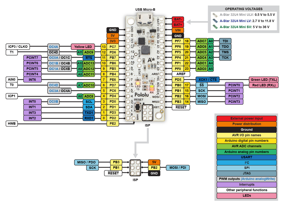 |
A-Star 32U4 Mini pinout diagram (listed SV voltage range is for original ac02c version). |
|---|
Like the A-Star Micro, the A-Star Minis are Arduino-compatible boards based on the ATmega32U4. The Minis are expanded boards that provide access to almost all of the pins of the AVR (including a few more than the Arduino Leonardo and Arduino Micro), but what really sets them apart from competing products are their efficient power supply systems based on switching regulators. Each model is based on a different voltage regulator, and its name includes a designation corresponding to its input voltage range:
- A-Star 32U4 Mini ULV (Ultra-Low Voltage): 0.5 V to 5.5 V
- A-Star 32U4 Mini LV (Low Voltage): 2.7 V to 11.8 V
- A-Star 32U4 Mini SV (Standard Voltage): 5 V to 36 V
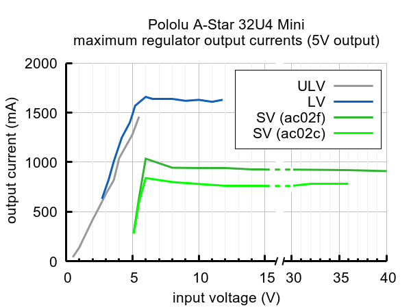 |
Typical maximum output current of the regulators on the A-Star 32U4 Mini boards. |
|---|
The regulator designs are closely related to some of our favorite voltage regulator boards, the U1V11F5, S7V8F5, and D24V5F5. Taken together, this range of options lets you power your project with anything from a single NiMH cell to a 24 V lead-acid battery or an 8-cell LiPo pack. With typical currents of 500 mA to 1 A, you get plenty of 5 V power for your AVR and an array of peripheral devices, or at the other end of the scale, these regulators allow your project to make effective use of low-power modes on the AVR, potentially operating on a battery for months at a time.
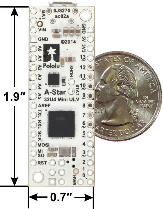 |
A-Star 32U4 Mini ULV, bottom view with dimensions. |
|---|
Another exciting feature of the power supply system on the A-Star Minis is seamless USB power switching provided by an onboard TPS2113A power multiplexer. This means that you can safely connect both USB and external power, and you can monitor or control the selected supply, without losing power or shorting your supplies together.
We think that the A-Star Minis are by far the most capable AVR breakout boards for their size, and they should be an excellent choice for almost any project needing a compact, Arduino-compatible controller. We have priced them so that it should be an easy choice, too. For more information or to order, see the A-Star controller category.
Related products


The Manufacturing of A-Star 32U4 Micro
We recently released the A-Star 32U4 Micro, which we think is the best available AVR breakout board for its size. If you are like us, you enjoy taking factory tours, seeing how things are made on How It’s Made, and watching your Krispy Kreme doughnuts get created right before you personally eat them. Since most of you have not been able to visit us here in Las Vegas, we’ve made a video that shows how your A-Star Micro gets made!
The video shows how the A-Star Micro goes from a bare printed circuit board to an assembled and tested product. It is one of our more complex boards to make because it has components on both sides—this means two trips through the stencil printer, pick-and-place machine, reflow oven, and automated optical inspection machine. Here are some of the machines featured in the video:
- Speedprint SP700 AVI stencil printer
- Samsung SM421F pick and place
- Heller 1707 MK III reflow oven
- Nordson YESTECH BX-12 automated optical inspection
|
|
For those of you who like to be mesmerized by big machines moving thousands of tiny components quickly, we also have a video that shows the full pick-and-place sequence of a panel of forty A-Star Micros. (Note that this is not an accurate representation of the assembly time since the feeders are moved to the side to make room for the camera.)
For more videos like these, see our YouTube playlist: Pololu manufacturing: how our products are made and subscribe to our channel. By the way, you can still get a free A-Star Micro with your order over $100.
Related products

Apeiros robot Kickstarter
 |
Abe Howell posted to our forum about a Kickstarter campaign for a robot he calls Apeiros. It is an open-source robot he designed as a teaching tool for STEM. Apeiros uses some of our parts and our laser cutting service in its construction. It is also designed to be upgraded with some of our sensors like the QTR-3 or QTR-8 reflectance sensor arrays or the Sharp GP2Y0D810Z0F Digital Distance Sensor. Some of the higher pledge rewards on the Kickstarter include these sensors. You can learn more about the robot on its Kickstarter page.
Related products


New products: Scooter wheel adapters
|
|
You have probably seen wheels on things like scooters, skateboards, baby-strollers, and inline skates, and noticed just how similar these common wheels are in size and shape. In fact, they are so similar that the industries built up around them have converged upon using a few standard bearings. We found that one of the most popular bearings used with wheels like those is the metric 608 ball bearing. The 608 bearing has well defined tolerances, measures 22 mm wide by 7 mm tall, and features an 8 mm bore.
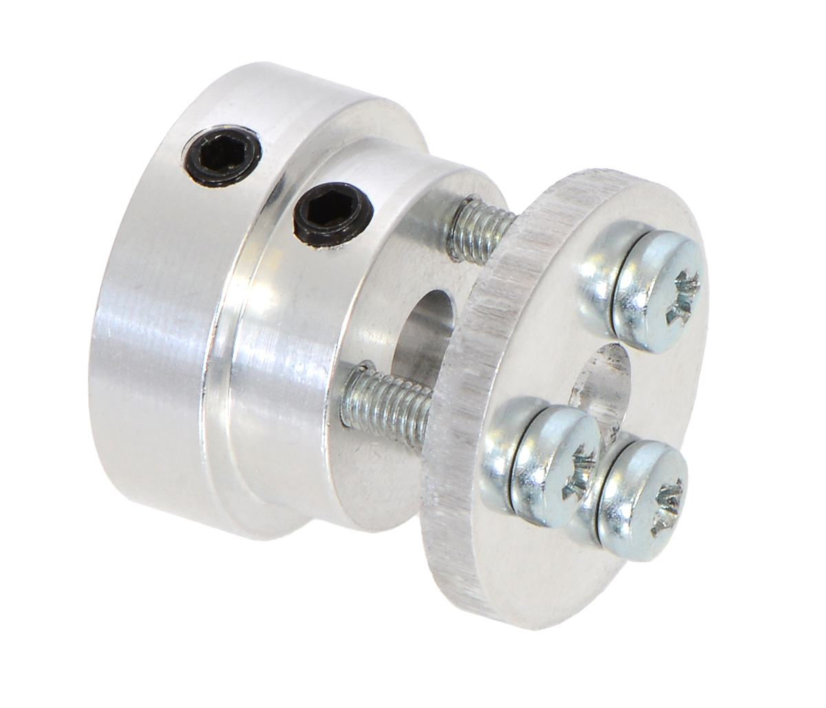
We recently used these measurements to create a series of adapters that enables you to use these widely-available wheels as drive wheels, which opens up a much larger variety of wheels to use with our motors!
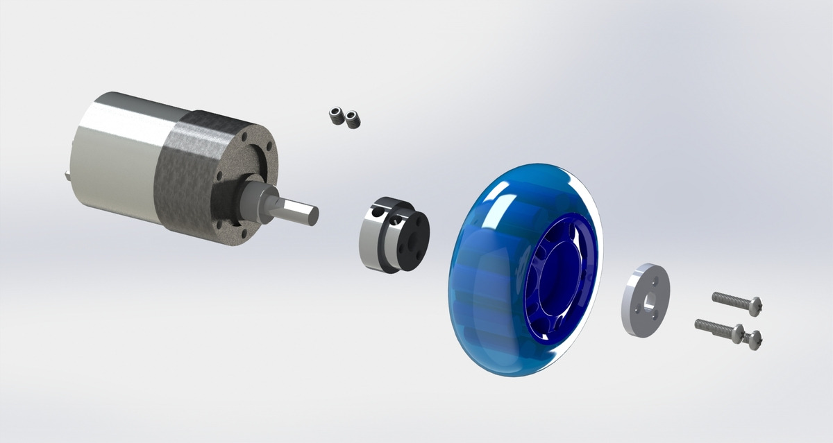 |
Exploded view of the scooter wheel adapter assembly with a gearmotor and scooter wheel. |
|---|
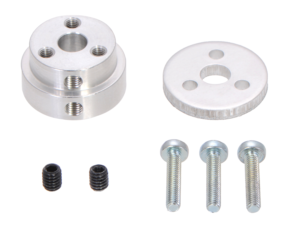
These adapters mount via set screw(s) to your motor’s output shaft (works best with D-shaped output shafts) and clamp tightly to the wheel.
|
|
|
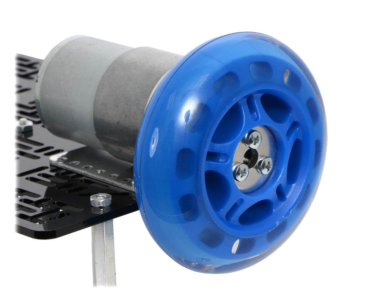
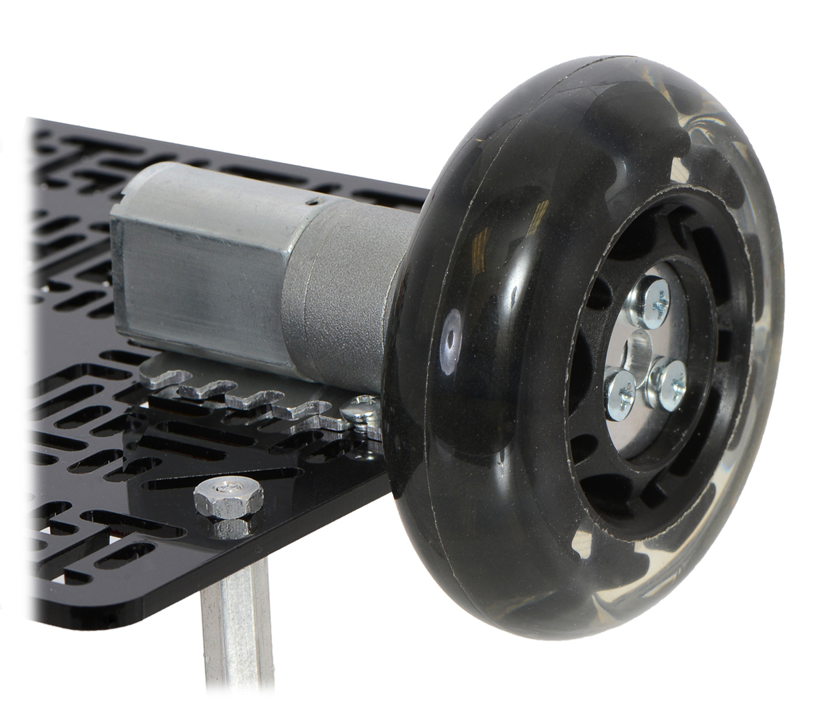
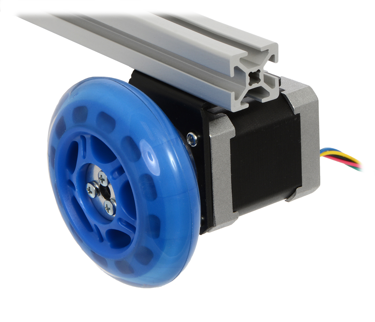
We have versions of these adapters that support our gearmotors with 4 mm, 5 mm, and 6 mm shafts.
Related products


Version 2.0.0 of minimu9-ahrs released
This week I released version 2.0.0 of minimu9-ahrs, an open-source demo program that runs on the Raspberry Pi, reads data from a MinIMU-9 via I²C, and uses the readings to calculate the orientation of the IMU. The new version adds support for the MinIMU-9 v3. The program now supports all past and present versions of the MinIMU-9.
The original version of minimu9-ahrs was released back in 2012, along with ahrs-visualizer, a program for displaying the orientation in 3D. For more background, you can see my blog post about minimu9-ahrs from 2012 or read the Raspberry Pi blog post about it from June 2014. The video below shows minimu9-ahrs and ahrs-visualizer working together:
Version 2.0.0 of minimu9-ahrs also includes some other changes:
In this new version, the raw accelerometer readings that you can get using the --mode raw option have basically been multiplied by 16 from what they were before. We made this same change to our LSM303 Arduino library when we added support for the LSM303D. The reason for this change is that before the MinIMU-9 v3, all the MinIMU-9 accelerometers were 12-bit, with the lower 4 bits of the output registers being unused, so we always shifted the readings to the right by 4 bits to get rid of the unused bits. The LSM303D in the MinIMU-9 v3 has a 16-bit output, so shifting its readings to the right by 4 bits would be inappropriate. However, it is nice for the raw accelerometer readings to have the same scale regardless of which accelerometer you happen to be using, so we chose to stop shifting the output of any of the accelerometers. All the accelerometers are configured to have a full-scale range of ±8 g by minimu9-ahrs, so a reading of 4096 will always correspond to about 1 g. This change should not affect most users, but it is not backwards-compatible, so, following semantic versioning, I incremented the major version number from 1 to 2.
The Debian package that I made for minimu9-ahrs version 2.0.0 uses the armhf architecture instead of armel (which was used for previous versions), so you can easily install it on a Raspberry Pi running Raspbian. I also made a new version of ahrs-visualizer that has an armhf package. If you are not using a Debian-based distribution like Raspbian or you are not using the armhf architecture, you can still compile the programs from source.
With this new version of minimu9-ahrs and our recent big price reduction of Pololu IMUs (which made the MinIMU-9 less expensive than a Raspberry Pi), now is a great time to start experimenting with these state-of-the-art MEMS sensors.
Related past posts
- Big price reduction of Pololu MEMS sensor carriers and IMUs
- New product: AltIMU-10 v4 gyro, accelerometer, compass, and altimeter
Related products


Home | Forum | Blog | Support | Ordering Information | Lists | Distributors | BIG Order Form | About | Contact
© 2001–2026 Pololu Corporation


