Robot Kits » Zumo Robots and Accessories » Zumo Robot for Arduino »
Zumo Reflectance Sensor Array

This reflectance sensor module is designed for use with the Zumo shield for Arduino. It has six IR LED/phototransistor pairs that can be used for line following or edge detection; each sensor provides an independent, digital I/O-measurable output. The array draws approximately 40 mA when the emitters are on, and an optional input allows the emitters to be turned off for additional sensing or power-saving options.
 Compare all products in Zumo Robot for Arduino or Older QTR Sensors.
| Description | Specs (3) | Pictures (6) | Resources (4) | FAQs (0) | On the blog (2) | Distributors (50) |
|---|
Note: This product is specifically designed to work with the Zumo shield for Arduino. For an alternative that works with our newer Zumo 32U4 robots, see the Zumo 32U4 Front Sensor Array.
 |
Zumo reflectance sensor array with labeled sensors and dimensions. |
|---|
Overview
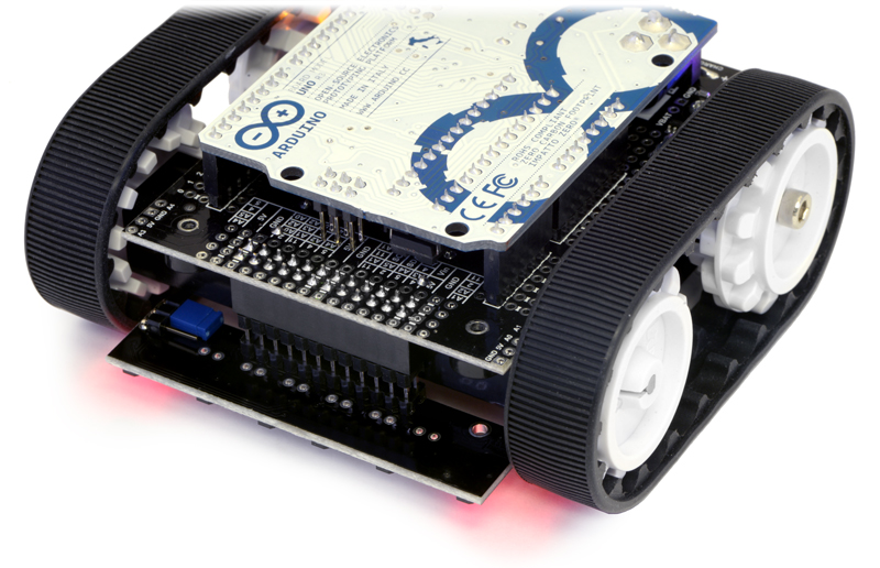
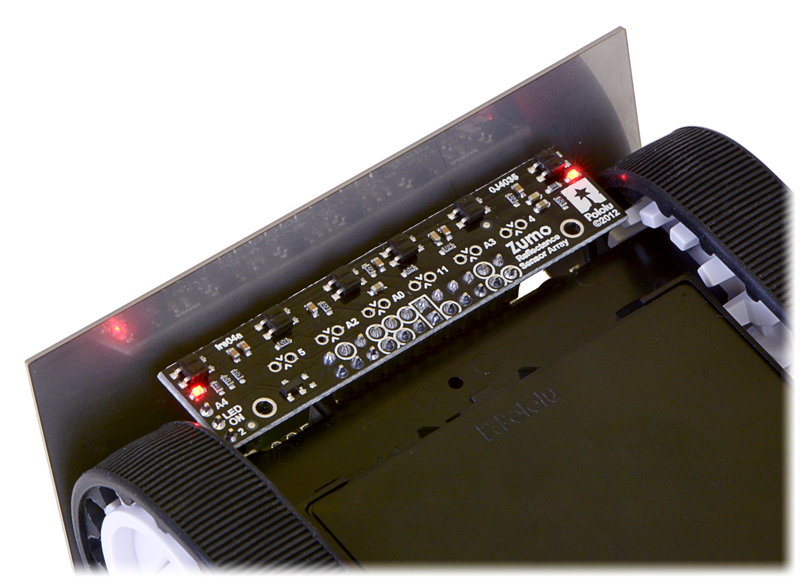
The Zumo reflectance sensor array provides an easy way to add line sensing or edge detection to a Zumo robot. It features six separate reflectance sensors, each consisting of an IR emitter coupled with a phototransistor that responds based on how much emitter light is reflected back to it. The two outside sensors are positioned at the very edges of the module to maximize their usefulness as edge detectors (e.g. for seeing the white edge of a sumo ring) while the four inner sensors are closer together for better detecting lines. This sensor is included with the assembled version of the Zumo robot, but not with the kit version.
The sensor array plugs into the front expansion header of the Zumo shield, which provides it with power and the necessary I/O connections. The default I/O connections are to pins that are otherwise unused by the Zumo shield, but the sensor module makes it possible to remap these pins or disconnect specific sensors altogether to free up I/O lines. Please see the Zumo Shield user’s guide for detailed information about assembly and use with the Zumo robot.
|
|
Included components
The Zumo reflectance sensor array ships with all of the components you need to connect it to a Zumo shield:
|
|
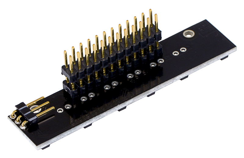
The short ends of the extended 2×12 male header strip should be soldered to the board as shown above (with the solder joints made on the component side of the array). The included 2×12 female header should be soldered to the front expansion area of the Zumo shield as described in the Zumo shield user’s guide. The array also ships with two 1×3 male headers: a straight version and a right-angle version. You can optionally solder the 1×3 header of your choice to the set of three holes along the edge of the board and use the included shorting block to connect the appropriate I/O line to the LEDON pin for dynamic control of the IR emitters (note: it is generally easier to install the 3-pin header before the larger 24-pin header). If you are content just having the IR emitters on all the time, you can skip installation of the 1×3 header. The assembled picture above shows the right-angle header installed.
How it works
 |
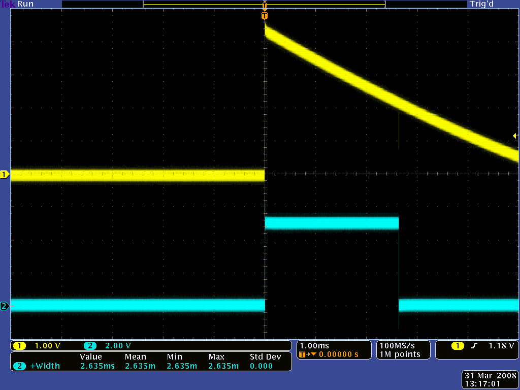 |
QTR-1RC output (yellow) when 1/8" above a black line and microcontroller timing of that output (blue). |
|---|
The array uses the same sensor modules as our QTR reflectance sensors and has the same principle of operation as our QTR-8RC version. The procedure for reading each sensor is as follows:
- Turn on IR LEDs (optional).
- Make the I/O line connected to that sensor an output and drive it high.
- Wait several microseconds to give the 1 nF capacitor node time to reach 5 V.
- Make the I/O line an input (with internal pull-up disabled).
- Measure the time for the voltage to decay by waiting for the I/O line to go low.
- Turn off IR LEDs (optional).
These steps can typically be executed in parallel for all six sensors. Our Zumo Arduino library provides functions for reading the sensors and controlling the emitters (as well as high-level functions for taking calibrated readings and determining the position of a line), so you do not have to program this sequence of steps yourself.
With a strong reflectance, the decay time can be as low as several dozen microseconds; with no reflectance, the decay time can be up to a few milliseconds. Meaningful results can be available within 1 ms in typical cases (i.e. when not trying to measure subtle differences in low-reflectance scenarios), allowing up to 1 kHz sampling of all 6 sensors. If lower-frequency sampling is sufficient, substantial power savings can be realized by turning off the LEDs. For example, if a 100 Hz sampling rate is acceptable, the LEDs can be off 90% of the time, lowering average current consumption from 40 mA to 4 mA.
To minimize the required emitter current, the IR LEDs are arranged in two parallel chains of three and powered from the Zumo shield’s boosted 7.45 V. Each chain of emitters is wired in series with a red LED, making it possible to tell when current is flowing through that chain (it is not possible to tell if the IR LEDs are on by looking at them with the unaided eye). All of the IR emitter LEDs are controlled by a single MOSFET that is gated by a digital LEDON input that enables the emitters when left disconnected or driven high. If this input is driven low, the emitters are disabled. Turning the LEDs off might be advantageous for limiting power consumption when the sensors are not in use or for varying the effective brightness of the LEDs through PWM control. Additionally, reading the sensors with the emitters turned off makes it possible to detect (and potentially compensate for) any ambient IR that might be interfering with readings. When the emitters are on, the sensor array draws approximately 40 mA.
Schematic diagram
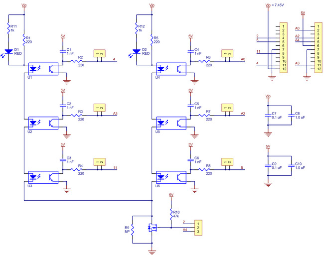 |
This schematic diagram is also available as a downloadable pdf (211k pdf).
Related products


Related categories


Home | Forum | Blog | Support | Ordering Information | Lists | Distributors | BIG Order Form | About | Contact
© 2001–2026 Pololu Corporation
