Support » Pololu Zumo Shield for Arduino User’s Guide » 2. Assembly »
2.c. Adding a Zumo reflectance sensor array (optional)
Overview
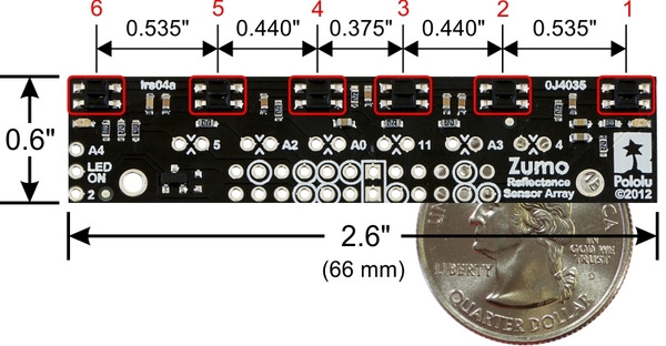
The Zumo reflectance sensor array is an easy way to add line-following and edge-detection capabilities to the Zumo robot. It is designed specifically to mount to the front expansion area of the Zumo shield, and it includes everything you need for installation. Note that the reflectance sensor array is not included with the Zumo shield or Zumo Robot Kit, and the Zumo robot can be used without it. For more information on the Zumo reflectance sensor’s capabilities and how it works (including a schematic diagram), please see its product page. This section is devoted specifically to assembling the sensor and using it with the Zumo shield.
 |
Assembling the sensor array
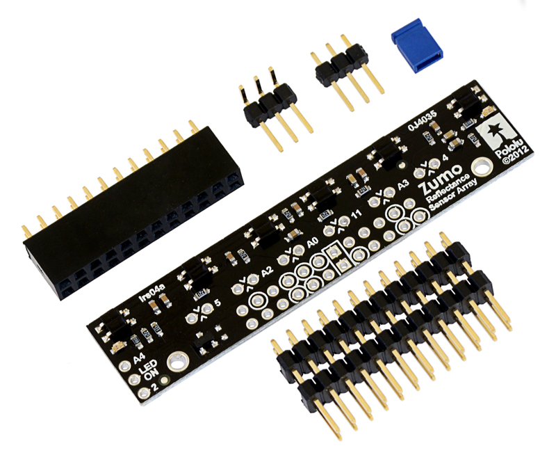 |
The Zumo reflectance sensor array ships with all of the components you need to connect it to a Zumo shield:
- sensor array PCB with the surface-mount parts pre-populated
- 2×12 extended 0.1″ male header (will be soldered to sensor PCB)
- 2×12 0.1″ female header (will be soldered to Zumo shield)
- 1×3 0.1″ straight male header (optionally soldered to sensor PCB)
- 1×3 0.1″ right-angle male header (optionally soldered to sensor PCB)
- blue shorting block
Before soldering in the main male header strip, we recommend soldering one of the two included 1×3 male headers into the set of three holes along the edge of the board. This step is optional but recommended because it allows dynamic control of the IR emitters (and red LEDs). By controlling when these LEDs are on, you can save power and make your programs easier to debug. If you skip this step, the IR emitters will just be on whenever the sensor array is plugged in and the Zumo is on. We recommend using the right-angle header mounted as shown in the picture below, but the straight 3-pin header will also work if you do not have anything already soldered to the Zumo shield’s front expansion area that would interfere. If you choose to install this header, please make sure you are doing it in a way that will not prevent installation of the sensor array (e.g. by installing it on the wrong side or by installing the right-angle pins in the wrong orientation)! If you are going to install this 3-pin header, it is generally easier to do so before soldering the larger 24-pin header.
To enable dynamic control of the IR emitters, install the 3-pin header and use the included blue shorting block to connect the LEDON pin to the appropriate digital I/O pin. If you are using an Arduino Uno or older Arduino, you should use the shorting block to connect LEDON to digital pin 2 (the position that puts it flush with the edge of the board); if you are using an Arduino Leonardo or A-Star 32U4 Prime, you should use the shorting block to connect LEDON to analog pin 4 (A4).
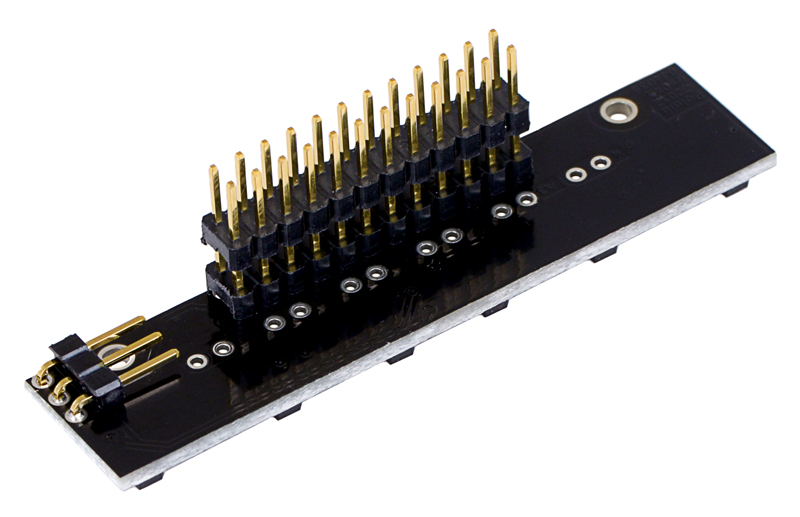 |
The extended 2×12 male header strip should be mounted to the sensor array PCB on the opposite side from the components. Make sure you solder the shorter side of the pins to the PCB, not the longer side! Note that only 12 of the 24 pins are actually used by the sensor array; these pins have silkscreen circles around them on the component side of the board, and these are the only pins that need to be soldered, though it is fine to solder all 24 pins.
Connecting to the Zumo shield
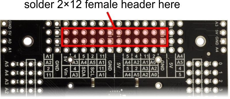
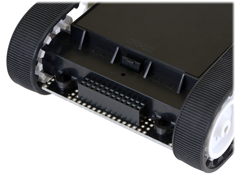
The 2×12 female header included with the reflectance sensor array should be soldered to the front expansion area of the Zumo shield so that it is centered in the expansion area and flush with the Zumo chassis (rows 2 and 3). While it is fine to solder all 24 pins to the shield, only the 12 pins required by the reflectance sensor array need to be soldered (see the Array pinout section below for more information on which pins are required).
 |
 |
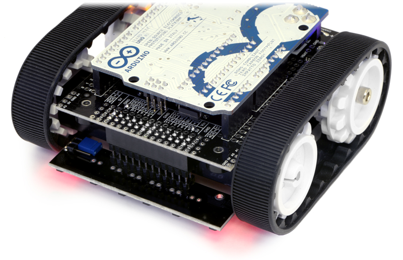
With the female header in place, the assembled sensor array can be plugged directly into the Zumo shield.
|
|
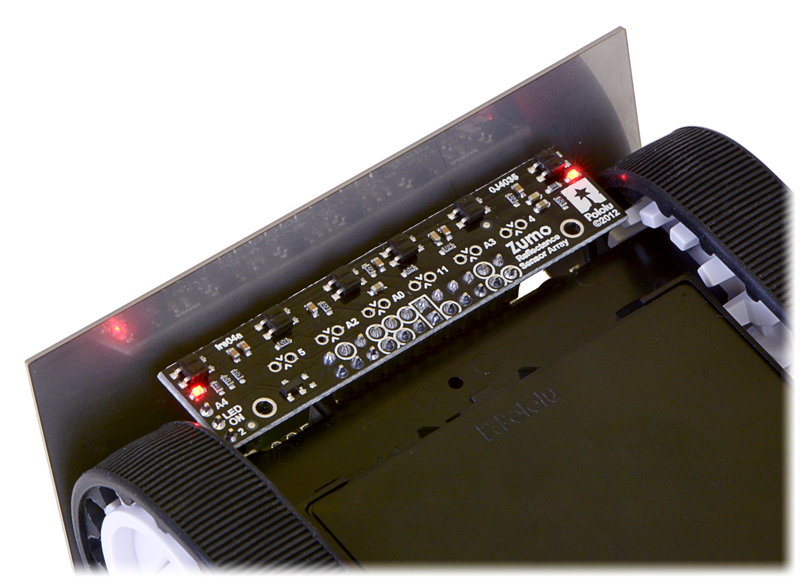
The reflectance sensor array features two visible (red) LEDs in series with the IR emitter LEDs, so you can use the red LEDs to tell when the emitters are on and off.
Array pinout
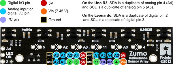
The Zumo reflectance sensor array gets all the necessary power and I/O connections from the 12 header pins that are circled on the silkscreen:
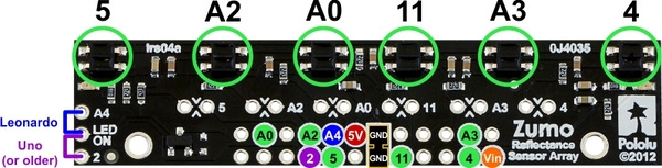 |
The default I/O connections are to pins that are otherwise unused by the Zumo shield. The shield uses one digital I/O pin for each sensor (5, A2, A0, 11, A3, and 4), and if you add the LEDON shorting block, one additional pin (either A4 or 2) is used. To configure the ZumoReflectanceSensorArray object to use this default pinout, simply call init with no arguments:
reflectanceSensors.init();
If you opt to leave off the LEDON shorting block, you should use the QTR_NO_EMITTER_PIN initialization parameter: reflectanceSensors.init(QTR_NO_EMITTER_PIN). Otherwise, the library code will still be trying to do something with the emitter pin (A4 or 2, depending on which Arduino you are using), and this would interfere with your being able to use that pin for alternate purposes.
When soldering the male 2×12 header to the sensor array, you only need to solder those pins that you will be using. If you solder all 24 pins, the sensor array will be connected to additional pins from the Zumo shield’s front expansion area, though the array does not do anything with them in its default configuration:
 |
Disabling or remapping sensors
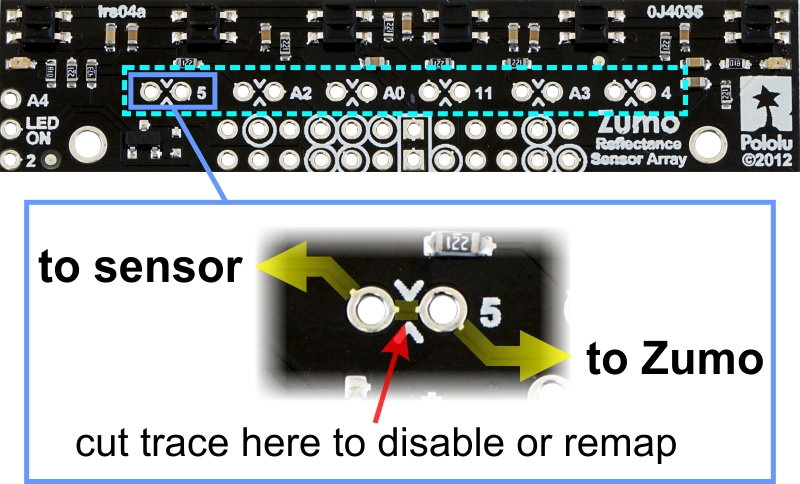
Many applications do not require all six reflectance sensors, and you might want additional I/O lines for other things (e.g. obstacle detectors). In such cases, you can disable specific sensors and free up their associated I/O lines. The array PCB has six pairs of through holes, each of which corresponds to a different sensor. The order of the pairs matches the order of the sensors. When viewing the component side of the PCB, the right hole of each pair connects to an Arduino I/O line and the left hole connects to sensor. There is a single trace on the component side of the PCB between the two holes of each pair, and this trace can be cut to disable the sensor and free up the I/O line. The proper place to cut is marked on the silkscreen by carets.
 |
For example, if you want to use your Zumo for solving a line maze, you can likely get by with just four sensors: you can use the middle two sensors for tracking the line and the outer two sensors for detecting intersections. To free up the I/O lines associated with the other two sensors, you could make the following modification:
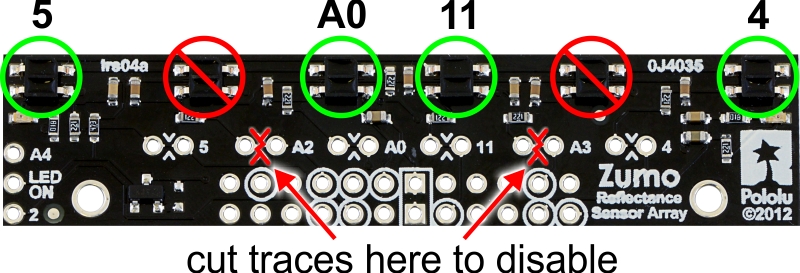 |
Now you effectively have a four-sensor array and analog pins A2 and A3 are available for general-purpose use. To configure the ZumoReflectanceSensorArray object to use this new configuration, call init with these arguments:
byte pins[] = {4, 11, A0, 5};
reflectanceSensors.init(pins, 4);
Alternatively, you could make two ZumoReflectanceSensorArray objects, one for the two exterior sensors and another for the two interior sensors, which might allow for cleaner code, but the drawback is that you can no longer read all four sensors in parallel with this approach.
If you later decide you want to re-enable those sensors, you can connect across the cut trace with a wire, or you can use a wire to remap the sensor to a different pin. The following example shows how you could re-enable the A2 sensor and remap the A3 sensor to pin A5 instead:
 |
To configure the ZumoReflectanceSensorArray object to use this remapped configuration, call init with these arguments:
byte pins[] = {4, A5, 11, A0, A2, 5};
reflectanceSensors.init(pins, 6);
Or, if you are not using an I/O line to control the IR emitters:
byte pins[] = {4, A5, 11, A0, A2, 5};
reflectanceSensors.init(pins, 6, 2000, QTR_NO_EMITTER_PIN);  // 2000 = timeout after 2 ms


Home | Forum | Blog | Support | Ordering Information | Lists | Distributors | BIG Order Form | About | Contact
© 2001–2026 Pololu Corporation
