Motors and Gearboxes » Linear Actuators » Glideforce Industrial-Duty (ID) Linear Actuators »
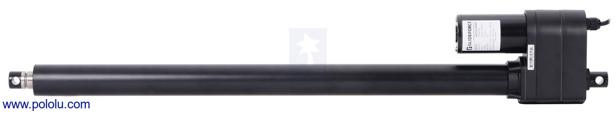
Glideforce LACT24-1000BPL Industrial-Duty Linear Actuator with Ball Screw Drive and Feedback: 450kgf, 24" Stroke (23.5" Usable), 0.66"/s, 12V

This 12 V industrial-duty (ID) linear actuator uses an efficient ball screw drive to lift loads up to 450 kgf [1000 lbs or 4500 N] and withstand static loads up to 1360 kgf [3000 lbs or 13,600 N]. It has a maximum speed of 16.8 mm/s [0.66″/s] at no load and 14.3 mm/s [0.56″/s] at the maximum load. Limit switches at each end make the actuator easy to control over its full range of motion, and an overload clutch protects the actuator from being damaged by excessive loads. The shaft holds its position when unpowered. This version has a 24-inch stroke (23.5″ usable) and a feedback potentiometer that lets you determine where the actuator is in its stroke.
Alternatives available with variations in these parameter(s): max linear force @ 12V nominal stroke length feedback potentiometer included? Select variant…
 Compare all products in Glideforce Industrial-Duty (ID) Linear Actuators.
| Description | Specs (20) | Pictures (7) | Resources (4) | FAQs (0) | On the blog (0) | Distributors (0) |
|---|
Overview
Warning: Do not allow the extension shaft of this industrial-duty linear actuator to rotate when it is extending or retracting. Allowing the shaft to rotate during operation can result in permanent misalignment of the shaft relative to the limit switches (and potentiometer, in the versions with feedback).
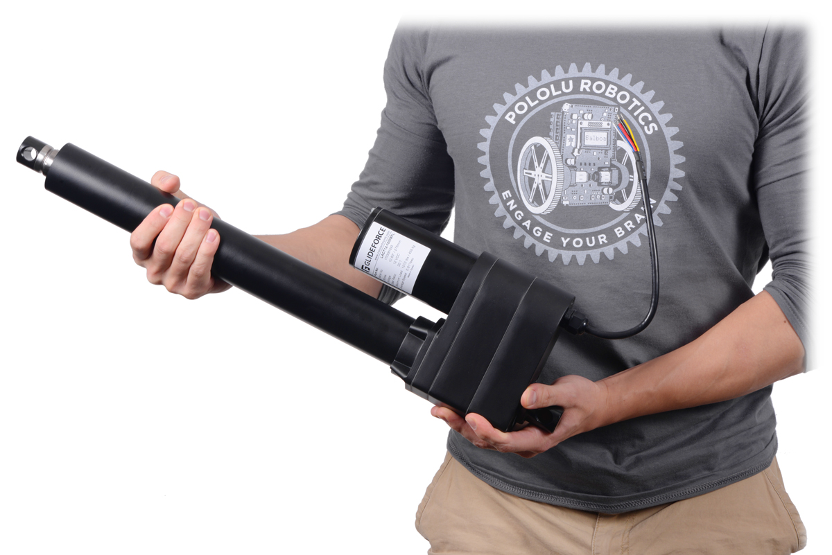 |
The Industrial-Duty (ID) series of Glideforce linear actuators by Concentric International (formerly Iowa Export-Import) are powerful 12V DC gearmotors that use an acme screw drive or ball screw drive to move a shaft back and forth along its length. The shaft will hold its position even when unpowered. The versions with acme screw drives (part number LACTx-500Ax) can move loads up to 250 kgf [550 lbs or 2500 N] and withstand static loads up to 450 kgf [1000 lbs or 4500 N], while versions with more efficient ball screw drives (part number LACTx-1000Bx) can move loads up to 450 kgf [1000 lbs or 4500 N] and withstand static loads up to 1360 kgf [3000 lbs or 13,600 N].
Two limit switches safely stop the motor at either end of its range, while integrated diodes allow it to reverse direction after reaching a limit point if the supplied voltage is reversed, and a built-in overload clutch protects the actuator from excessive dynamic loads. The actuators have an all-steel frame and extension tube, and the entire case is sealed to protect against dust and water (rated IP65).
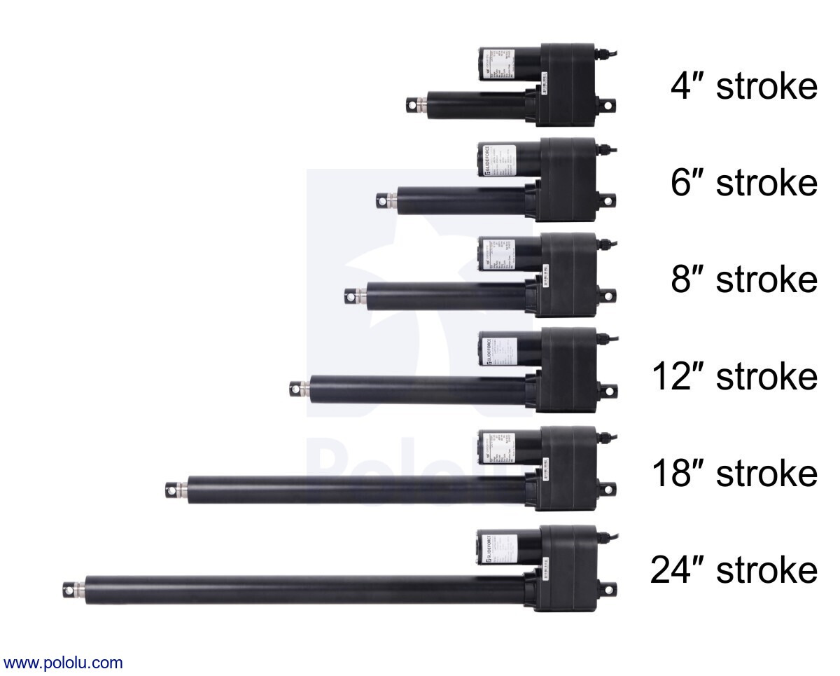
These actuators are available in a variety of stroke lengths, from 4″ to 24″, and with optional potentiometers that are linked to the shaft position, for use in feedback systems:
| Actuator Type |
Max Dynamic Load |
No-Load Speed @ 12 V |
Max-Load Speed @ 12 V |
Current Draw @ 12 V |
Nominal Stroke Length |
With Feedback |
Without Feedback |
|---|---|---|---|---|---|---|---|
| Industrial-Duty (ID) with Acme screw drive |
250 kgf [550 lb] |
1.7 cm/s [0.66″/s] |
1.4 cm/s [0.56″/s] |
2.4 A – 13.2 A |
4″ | LACT4-500APL | LACT4-500AL |
| 6″ | LACT6-500APL | LACT6-500AL | |||||
| 8″ | LACT8-500APL | LACT8-500AL | |||||
| 12″ | LACT12-500APL | LACT12-500AL | |||||
| 18″ | LACT18-500APL | LACT18-500AL | |||||
| 24″ | LACT24-500APL | LACT24-500AL | |||||
| Industrial-Duty (ID) with ball screw drive |
450 kgf [1000 lb] |
1.7 cm/s [0.66″/s] |
1.4 cm/s [0.56″/s] |
2.4 A – 13.2 A |
4″ | LACT4-1000BPL | LACT4-1000BL |
| 6″ | LACT6-1000BPL | LACT6-1000BL | |||||
| 8″ | LACT8-1000BPL | LACT8-1000BL | |||||
| 12″ | LACT12-1000BPL | LACT12-1000BL | |||||
| 18″ | LACT18-1000BPL | LACT18-1000BL | |||||
| 24″ | LACT24-1000BPL | LACT24-1000BL | |||||
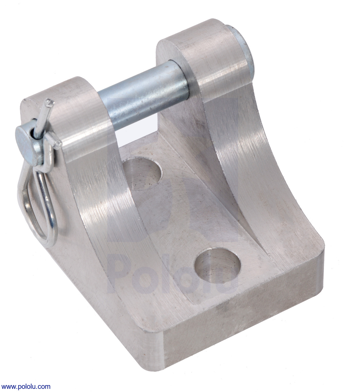
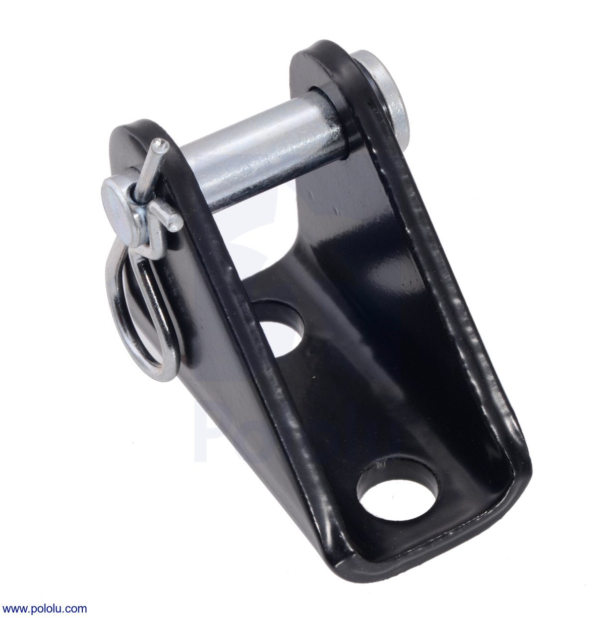
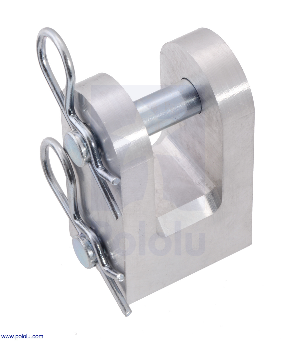
Heavy-duty mounting brackets made from machined aluminum or stamped steel are available for attaching the actuators to a structure; two are required for each actuator. A mounting clevis is also available for converting either actuator end into a clevis-style.
|
|
|
Details for item #3634
 |
- Concentric item number: LACT24-1000BPL
- Nominal stroke length: 24″ [61.0 cm]
- Actual stroke length: 23.58″ [59.9 cm]
- Retracted length: 36.85″ [93.6 cm] (from mounting hole to mounting hole)
- Extended length: 60.43″ [153.5 cm] (from mounting hole to mounting hole)
- Weight: 16.2 lb [7.4 kg]
- Gear ratio: 20:1 (standard)
- Efficient ball screw drive
- Rated dynamic load capacity: 1000 lbs [450 kgf or 4500 N]
- Maximum static load: 3000 lbs [1360 kgf or 13,600 N]
- Feedback potentiometer
ID series features and specifications
The following specifications apply to all Glideforce ID series linear actuators with the standard 20:1 gear ratio:
 |
Glideforce Industrial-Duty (ID) series of linear actuators. |
|---|
- Nominal operating voltage: 12 V
- Speed at 12 V, no load: 0.66 in/s [16.8 mm/s]
- Speed at 12 V, max load: 0.56 in/s [14.3 mm/s]
- Standard preset limit switches at both ends of stroke
- Overload clutch
- All steel frame and extension tube
- Aluminum gearbox housing
- Ball screw version has stainless steel extension tube
- All metal gears
- Noise level: ≤ 70 dB
- Mounting hole diameter: 1/2″ [13 mm]
- Working temperature: -13°F [-25°C] to 149°F [65°C]
- IP rating: IP65 (total dust protection, water resistant)
For more details, see the ID Acme Drive Series Datasheet (468k pdf) and ID Ball Drive Series Datasheet (486k pdf).
Dimensions
A dimension diagram of the ID linear actuators are shown below. It applies both to versions with limit switches (500AL and 1000BL) and to versions with limit switches and potentiometers (500APL and 1000BPL), though note that the actual stroke length is affected by the kind of drive screw (acme or ball). For more detailed information, including the retracted and extended lengths of each version, see the datasheet.
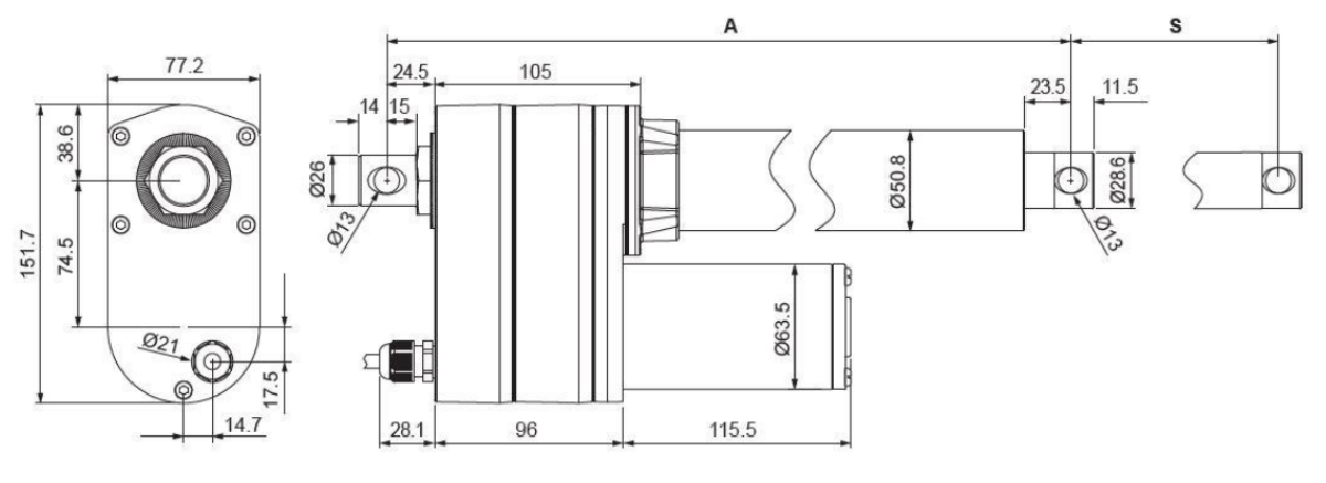 |
Dimensions of Glideforce ID linear actuators with limit switches (LACTx-500AL, LACTx-500APL, LACTx-1000BL, and LACTx-1000BPL). Units are mm. |
|---|
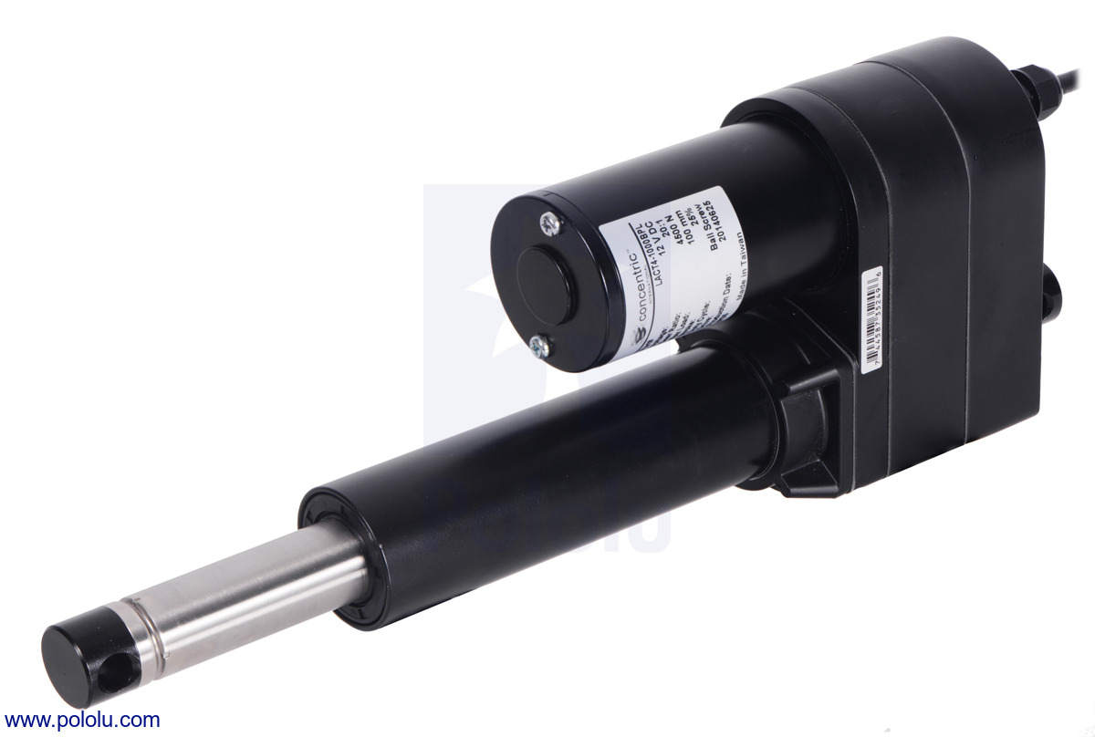 |
Glideforce LACT4 industrial-duty linear actuator (4″ stroke) with shaft fully extended. |
|---|
Using the actuator
Warning: Do not allow the extension shaft of this industrial-duty linear actuator to rotate when it is extending or retracting. Allowing the shaft to rotate during operation can result in permanent misalignment of the shaft relative to the limit switches (and potentiometer, in the versions with feedback).
To test-drive the actuator, connect a power source of up to 12 V to the motor leads while ensuring that the output shaft is not allowed to rotate relative to the actuator body as it extends or retracts. Reversing the applied voltage will reverse the direction of motion. A motor controller or motor driver is required for electronic speed and direction control. We recommend our Jrk G2 24v21 Motor Controllers for use with the feedback actuators (see below for more information on this) and the Simple Motor Controller G2 24v19 for controlling the actuators without feedback, though many of our other motor controllers and motor drivers are capable of powering this actuator.
These actuators have a stall current of approximately 50 A at 12 V, but they will, on average, draw far less than this when used within their load ratings. They draw around 2.4 A with no load and can exceed 13 A at their maximum rated dynamic load. However, please note that the actuators can briefly draw close to their full stall current when abruptly started or on a sudden change of direction. Such current spikes can be dampened if you take steps to limit the acceleration of the actuator (many of our motor controllers offer optional acceleration limiting).
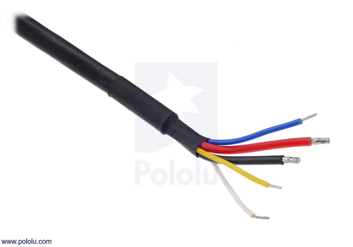
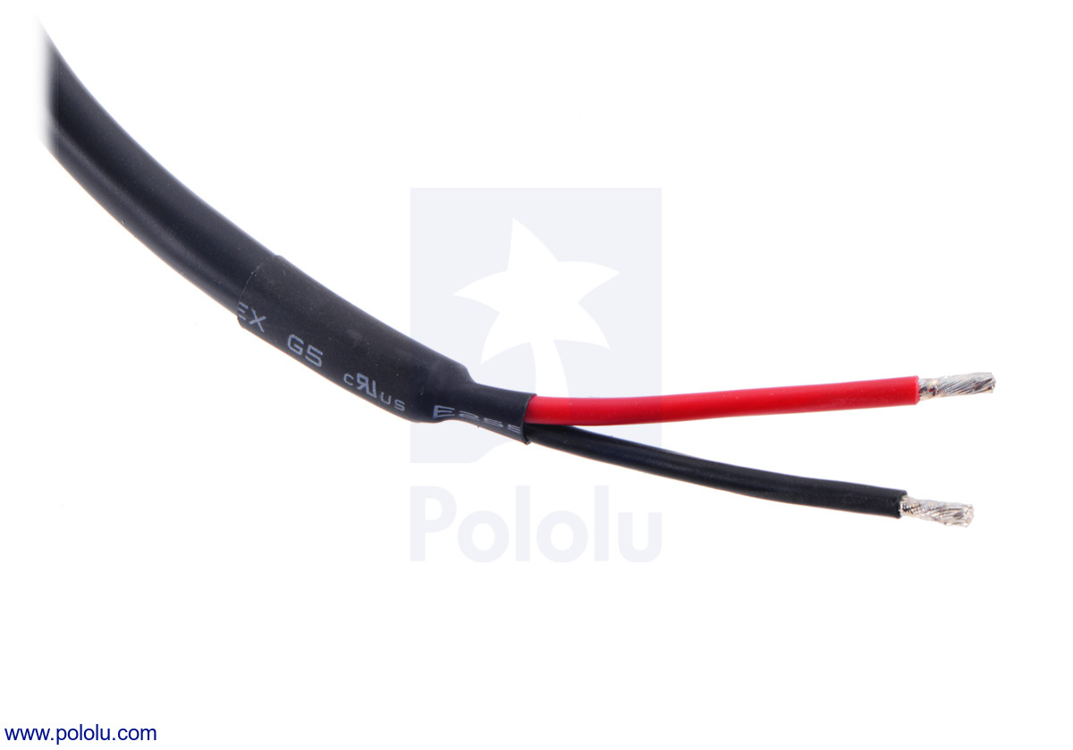
Actuator leads
The ID linear actuators have a 10″ (25 cm) cable ending in unterminated,stripped wires. The thick red and black wires are the motor leads. Actuators with feedback potentiometers have three additional thinner wires: white, yellow, and blue. White and yellow connect to the two ends of the 10 kΩ potentiometer, and blue connects to the wiper. If you connect white to ground and yellow to VCC, you can then read the voltage on blue to determine the position of the actuator (the voltage will increase from close to 0 V to close to VCC as the actuator goes from fully retracted to fully extended). The picture below shows the end of the cable for an ID linear actuator with feedback:
|
|
These actuators are not compatible with our extension cable for LD/MD linear actuators.
Using a Jrk G2 motor controller with a linear actuator with feedback
 |
Connecting an industrial-duty linear actuator with feedback to a Jrk 24v13 motor controller. |
|---|
The feedback features of our Jrk G2 24v21 motor controller make it a great solution for precisely controlling our linear actuators with feedback. Our settings file for the Jrk G2 configuration utility makes setup easy, eliminating the need to tune the PID constants. To get started, follow the steps below:
- If you have not already, read through the Jrk G2 Motor Controllers User’s Guide and download its drivers and configuration software.
- Before connecting power and your actuator to your Jrk, confirm that it is working by connecting your Jrk to a PC with a USB cable and launch the configuration utility. The red LED should be on, and the green LED should be flickering quickly.
- Download the Jrk 24v21 settings file for use with LACTx-500APL and LACTx-1000BPL (2k txt).
- In the configuration utility, choose File → Open settings file (Ctrl + O), and navigate to the location of the settings file you downloaded in step 3.
- Click on the PID tab of the configuration utility and verify that the proportional and derivative coefficients are not zero. If they are zero, the settings file was probably not loaded properly and you should try performing the previous step again.
- Click “Apply settings”.
- With your power supply off and USB disconnected, connect your linear actuator to your Jrk using the connections shown in the picture above.
- Turn on power, plug in USB, and reconnect to the configuration utility (use the “Connected to” drop down box if the configuration utility doesn’t automatically reconnect to your Jrk).
- On the Status tab, move the slider around to change the target position and get your actuator to move the target position.
- The PID settings in this file should work fairly well with any length Glideforce industrial-duty actuator that has a feedback potentiometer(models LACTx-500APL and LACTx-1000BPL). However, the range for the feedback potentiometer is very different for the various lengths and screw drive options on the industrial-duty actuators, and you might find decreased performance very near the extremes of the range due to the limit switches. To ensure you can control your actuator across its full stroke, you have to recalibrate the feedback. Instructions for doing this can be found in the analog feedback section of the Jrk G2 User’s Guide.
Other Glideforce linear actuator options
 |
Glideforce linear actuators, from left to right: 6″ Industrial Duty (ID), 6″ Medium Duty (MD), 6″ Light Duty (LD), 50 mm Micro. |
|---|
We carry a variety of Glideforce linear actuators, from the Micro GF01 series, which weigh under 60 g, through the industrial-duty ID series, which can withstand dynamic loads up to 1000 lb. The table below shows our full offering of these linear actuators, sorted by increasing dynamic load capabilities:
| Actuator Type |
Max Dynamic Load |
No-Load Speed @ 12 V |
Max-Load Speed @ 12 V |
Current Draw @ 12 V |
Weight | Nominal Stroke Length |
With Feedback (no limit switches) |
With Limit Switches (no feedback) |
||
|---|---|---|---|---|---|---|---|---|---|---|
 |
Micro (GF01) 50:1 |
2.2 kgf [4.9 lb] |
2.8 cm/s [1.1″/s] |
2.1 cm/s [0.8″/s] |
0.15 A – 0.4 A |
31 g | 1 cm | (0.39″) | — | GF01-120501-1-66 |
| 37 g | 3 cm | (1.2″) | GF01-120503-2-66 | GF01-120503-1-66 | ||||||
| 42 g | 5 cm | (2.0″) | GF01-120505-2-66 | GF01-120505-1-66 | ||||||
| 57 g | 10 cm | (3.9″) | GF01-120510-2-66 | GF01-120510-1-66 | ||||||
| Micro (GF01) 100:1 |
4.3 kgf [9.4 lb] |
1.8 cm/s [0.7″/s] |
1.2 cm/s [0.5″/s] |
0.15 A – 0.3 A |
31 g | 1 cm | (0.39″) | — | GF01-121001-1-66 | |
| 39 g | 3 cm | (1.2″) | GF01-121003-2-66 | GF01-121003-1-66 | ||||||
| 44 g | 5 cm | (2.0″) | GF01-121005-2-66 | GF01-121005-1-66 | ||||||
| 59 g | 10 cm | (3.9″) | GF01-121010-2-66 | GF01-121010-1-66 | ||||||
| Micro (GF01) 210:1 |
8.1 kgf [18 lb] |
0.9 cm/s [0.3″/s] |
0.6 cm/s [0.2″/s] |
0.15 A – 0.25 A |
31 g | 1 cm | (0.39″) | — | GF01-122101-1-66 | |
| 39 g | 3 cm | (1.2″) | GF01-122103-2-66 | GF01-122103-1-66 | ||||||
| 44 g | 5 cm | (2.0″) | GF01-122105-2-66 | GF01-122105-1-66 | ||||||
| 59 g | 10 cm | (3.9″) | GF01-122110-2-66 | GF01-122110-1-66 | ||||||
| Actuator Type |
Max Dynamic Load |
No-Load Speed @ 12 V |
Max-Load Speed @ 12 V |
Current Draw @ 12 V |
Weight | Nominal Stroke Length |
With Feedback |
Without Feedback |
||
 |
High-Speed Light-Duty (LD) 5:1 |
12 kgf [27 lb] |
8.4 cm/s [3.3″/s] |
7.5 cm/s [2.9″/s] |
1.1 A – 3.4 A |
1.1 kg | 2″ | (5 cm) | GF23-120502-3-65 | GF23-120502-1-65 |
| 1.2 kg | 4″ | (10 cm) | GF23-120504-3-65 | GF23-120504-1-65 | ||||||
| 1.3 kg | 6″ | (15 cm) | GF23-120506-3-65 | GF23-120506-1-65 | ||||||
| 1.3 kg | 8″ | (20 cm) | GF23-120508-3-65 | GF23-120508-1-65 | ||||||
| 1.4 kg | 10″ | (25 cm) | GF23-120510-3-65 | GF23-120510-1-65 | ||||||
| 1.5 kg | 12″ | (30 cm) | GF23-120512-3-65 | GF23-120512-1-65 | ||||||
| Light-Duty (LD) 5:1 |
15 kgf [34 lb] |
4.4 cm/s [1.7″/s] |
3.6 cm/s [1.4″/s] |
1.2 A – 3.2 A |
1.1 kg | 2″ | (5 cm) | LACT2P-12V-05 | LACT2-12V-05 | |
| 1.2 kg | 4″ | (10 cm) | LACT4P-12V-05 | LACT4-12V-05 | ||||||
| 1.3 kg | 6″ | (15 cm) | LACT6P-12V-05 | LACT6-12V-05 | ||||||
| 1.3 kg | 8″ | (20 cm) | LACT8P-12V-05 | LACT8-12V-05 | ||||||
| 1.4 kg | 10″ | (25 cm) | LACT10P-12V-05 | LACT10-12V-05 | ||||||
| 1.5 kg | 12″ | (30 cm) | LACT12P-12V-05 | LACT12-12V-05 | ||||||
| Light-Duty (LD) 10:1 |
25 kgf [55 lb] |
2.8 cm/s [1.1″/s] |
2.3 cm/s [0.9″/s] |
1.2 A – 3.2 A |
1.1 kg | 2″ | (5 cm) | LACT2P-12V-10 | LACT2-12V-10 | |
| 1.2 kg | 4″ | (10 cm) | LACT4P-12V-10 | LACT4-12V-10 | ||||||
| 1.3 kg | 6″ | (15 cm) | LACT6P-12V-10 | LACT6-12V-10 | ||||||
| 1.3 kg | 8″ | (20 cm) | LACT8P-12V-10 | LACT8-12V-10 | ||||||
| 1.4 kg | 10″ | (25 cm) | LACT10P-12V-10 | LACT10-12V-10 | ||||||
| 1.5 kg | 12″ | (30 cm) | LACT12P-12V-10 | LACT12-12V-10 | ||||||
| Light-Duty (LD) 20:1 |
50 kgf [110 lb] |
1.5 cm/s [0.57″/s] |
1.2 cm/s [0.48″/s] |
1.2 A – 3.2 A |
1.1 kg | 2″ | (5 cm) | LACT2P-12V-20 | LACT2-12V-20 | |
| 1.2 kg | 4″ | (10 cm) | LACT4P-12V-20 | LACT4-12V-20 | ||||||
| 1.3 kg | 6″ | (15 cm) | LACT6P-12V-20 | LACT6-12V-20 | ||||||
| 1.3 kg | 8″ | (20 cm) | LACT8P-12V-20 | LACT8-12V-20 | ||||||
| 1.4 kg | 10″ | (25 cm) | LACT10P-12V-20 | LACT10-12V-20 | ||||||
| 1.5 kg | 12″ | (30 cm) | LACT12P-12V-20 | LACT12-12V-20 | ||||||
| Actuator Type |
Max Dynamic Load |
No-Load Speed @ 12 V |
Max-Load Speed @ 12 V |
Current Draw @ 12 V |
Weight | Nominal Stroke Length |
With Feedback |
Without Feedback |
||
 |
Medium-Duty (MD) |
100 kgf [225 lb] |
1.5 cm/s [0.58″/s] |
1.0 cm/s [0.41″/s] |
1.1 A – 4.6 A |
1.1 kg | 4″ | (10 cm) | MD122004-P | MD122004 |
| 1.2 kg | 6″ | (15 cm) | MD122006-P | MD122006 | ||||||
| 1.3 kg | 8″ | (20 cm) | MD122008-P | MD122008 | ||||||
| 1.4 kg | 10″ | (25 cm) | MD122010-P | MD122010 | ||||||
| 1.5 kg | 12″ | (30 cm) | MD122012-P | MD122012 | ||||||
| Actuator Type |
Max Dynamic Load |
No-Load Speed @ 12 V |
Max-Load Speed @ 12 V |
Current Draw @ 12 V |
Weight | Nominal Stroke Length |
With Feedback |
Without Feedback |
||
 |
Industrial-Duty (ID) with Acme screw drive |
250 kgf [550 lb] |
1.7 cm/s [0.66″/s] |
1.4 cm/s [0.56″/s] |
2.4 A – 13.2 A |
4.2 kg | 4″ | (10 cm) | LACT4-500APL | LACT4-500AL |
| 4.4 kg | 6″ | (15 cm) | LACT6-500APL | LACT6-500AL | ||||||
| 4.7 kg | 8″ | (20 cm) | LACT8-500APL | LACT8-500AL | ||||||
| 5.3 kg | 12″ | (30 cm) | LACT12-500APL | LACT12-500AL | ||||||
| 6.0 kg | 18″ | (45 cm) | LACT18-500APL | LACT18-500AL | ||||||
| 7.0 kg | 24″ | (60 cm) | LACT24-500APL | LACT24-500AL | ||||||
| Industrial-Duty (ID) with ball screw drive |
450 kgf [1000 lb] |
1.7 cm/s [0.66″/s] |
1.4 cm/s [0.56″/s] |
2.4 A – 13.2 A |
4.6 kg | 4″ | (10 cm) | LACT4-1000BPL | LACT4-1000BL | |
| 4.9 kg | 6″ | (15 cm) | LACT6-1000BPL | LACT6-1000BL | ||||||
| 5.1 kg | 8″ | (20 cm) | LACT8-1000BPL | LACT8-1000BL | ||||||
| 5.6 kg | 12″ | (30 cm) | LACT12-1000BPL | LACT12-1000BL | ||||||
| 6.5 kg | 18″ | (45 cm) | LACT18-1000BPL | LACT18-1000BL | ||||||
| 7.4 kg | 24″ | (60 cm) | LACT24-1000BPL | LACT24-1000BL | ||||||
Related products


Related categories


Home | Forum | Blog | Support | Ordering Information | Lists | Distributors | BIG Order Form | About | Contact
© 2001–2026 Pololu Corporation
