Support » Jrk G2 Motor Controller User’s Guide » 5. Setting up the feedback method »
5.2. Setting up analog feedback
This section explains how to connect an analog feedback signal to the Jrk G2 and configure the Jrk G2 to do position control. Please note that this is different from setting up an analog control signal, which is documented in Section 6.4.
Connecting analog feedback
If you have not done so already, you should follow the instructions in Section 4.3 to configure and test your motor. Next, with the system unpowered, connect your analog feedback signal to the Jrk as described below.
If you are using a potentiometer to generate the analog feedback signal, then you should connect the potentiometer’s wiper to FBA. You should connect the other two ends of the feedback potentiometer to the power pins that are in line with FBA: on the Jrk G2 18v27 and 24v21, the pins are AUX and GND, while on the other Jrk G2 versions the pins are AUX and POT−.
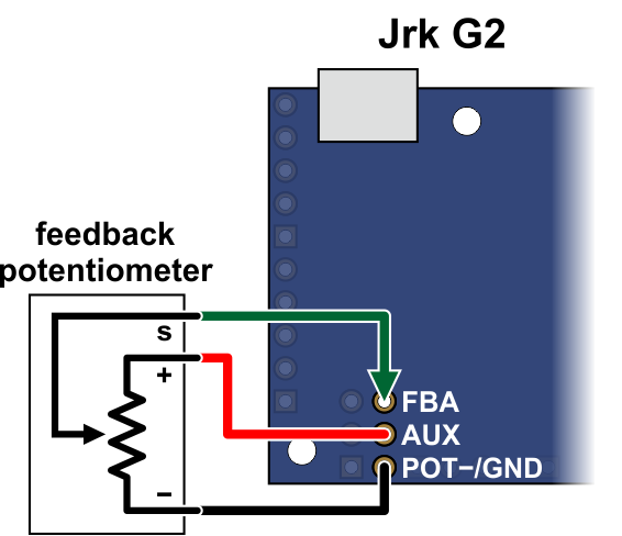 |
Connecting analog voltage feedback to the Jrk G2. |
|---|
If you are using something other than a potentiometer to generate the analog feedback signal, make sure that the ground node of that device is connected to a GND pin of the Jrk, and that the signal from that device is connected to the FBA pin. The Jrk can only accept signals between 0 V and 5 V with respect to GND; signals outside of this range could damage the Jrk.
Configuring and calibrating analog feedback
Now connect your Jrk to your computer via USB. In the Jrk G2 Configuration Utility, go to the “Feedback tab” and set the “Feedback mode” to “Analog voltage”.
If you are powering a feedback potentiometer from the AUX pin, you should check the “Detect disconnect with power pin (AUX)” checkbox. This causes the Jrk to drive AUX low periodically to help detect whether the feedback potentiometer has been disconnected.
Go to the “Errors” tab and set the “Feedback disconnect” error to “Enabled and latched”. Click the “Apply settings” button.
Turn on motor power.
Go to the “Feedback” tab, and in the “Scaling” box, click “Feedback setup wizard…”.
Steps 1 and 2 of the feedback setup wizard helps you configure the direction of your motor and the direction of your feedback. These steps ensure that a positive duty cycle corresponds to the motor moving in the direction that you consider to be forward in your system, and that this forward movement also causes the Jrk’s “Scaled feedback” variable to increase.
Step 3 of the feedback setup wizard lets you set the range of your feedback.
If possible, the range you enter in step 3 should be at least a little larger than the range of motion that you actually plan on using. Raw feedback values within this range get mapped to “Scaled feedback” values from 0 to 4095. Raw feedback values outside of the range will be mapped to a “Scaled feedback” value of either 0 or 4095, depending on whether they are below or above the range. The Jrk’s PID algorithm does not look at the raw feedback variable: it compares the “Scaled feedback” to the “Target” and drives the motor in attempt to eliminate the difference between those two, also known as the “Error”. If you set the “Target” to 0 or 4095 but something pulls your system outside of the feedback range entered in step 3, the “Scaled feedback” variable will not change so the Jrk will not know it should drive the motor to get the system back within the desired range.
Once you have finished the wizard, the new settings should be applied to the Jrk.
Testing basic feedback
At this point, the Jrk is almost ready to do position control. Go to the “PID” tab and enter a “Proportional coefficient” of 1, while leaving the other two coefficients set to zero. This will probably drive your motor at its maximum duty cycle, so make sure that this and other motor parameters are configured correctly. Click “Apply settings”.
Use the target slider at the bottom of the window to send various target values to your Jrk, and see how it behaves. The red dot on the slider shows the “Scaled feedback” value.
If you did everything correctly, your feedback system should now be active, approximately following the target value.
Troubleshooting basic feedback
If the steps above do not result in a working position feedback system, these tips can help you figure out what is wrong and get the system working.
First of all, look in the “Errors” tab and look at the status message at the bottom of the Jrk G2 Configuration Utility. These messages might tell you why things are not working.
It is possible that you did not do one of the steps of the Feedback wizard correctly. You might consider trying the wizard again and carefully reading each instruction.
To troubleshoot effectively, you should know a little bit about how the Jrk’s PID algorithm works.
- During each PID update period (which is 10 ms by default), the Jrk measures the analog voltage on the FBA pin and uses that to set the (raw) “Feedback” variable, which you can see in the Status tab of the Jrk Configuration Utility. A value of 0 should represent 0 V, while a value of 4092 represents approximately 5 V.
- The Jrk scales the raw feedback value using the scaling settings from the “Feedback” tab in order to compute the “Scaled feedback” value, which is also a number between 0 and 4095. Raw feedback values above the “Maximum” feedback value get mapped to a “Scaled feedback” value of 4095 (if the feedback direction is not inverted) or 0 (if the feedback direction is inverted. Raw feedback values below the “Minimum” feedback value get mapped to a “Scaled feedback” value of 0 (if the feedback direction is not inverted) or 4095 (if the feedback direction is inverted).
- The Jrk’s PID algorithm calculates the “Scaled Feedback” minus the “Target” (which is called the Error), multiplies it by the proportional coefficient, then multiplies by −1, and assigns that value to the “Duty cycle target” variable (assuming the derivative and integral coefficients are zero). A “Duty cycle target” of −600 represents full speed reverse while a “Duty cycle target” of 600 represents full speed forward, but the target can be outside of this range. A proportional coefficient of 1 means that the “Target” and “Scaled feedback” have to differ by 600 counts before the Jrk will drive the motor at full speed.
- The Jrk applies max duty cycle, max acceleration, and other motor limits to the “Duty cycle target” to produce the “Duty cycle” variable between −600 (full speed reverse) and 600 (full speed forward).
- The Jrk drives the motor at the specified duty cycle. The direction of the motor is determined by the sign of the “Duty cycle” variable and the “Invert motor direction” setting, which was determined in step 1 of the feedback setup wizard.
The “Status” tab displays the “Feedback”, “Scaled feedback”, “Target”, “Error”, “Duty cycle target”, and “Duty cycle” variables so you can see what is happening at each step of this process and figure out exactly where things are going wrong:
- Measure the analog voltage on the FBA pin with respect to GND and make sure it accurately reflects the position of your system.
- Compare those measurements to the “Feedback” variable, and make sure it accurately reflects the voltage on the FBA pin as described above.
- Make sure that the “Scaled feedback” values goes to roughly 4095 at your system’s extreme forward position (according to your definition of forward for your system), and goes to roughly 0 at your system’s extreme reverse position. If not, the feedback scaling settings should probably be adjusted.
- Make sure that the “Duty cycle target” is equal to the “Target” minus the “Scaled feedback” (assuming your proportional coefficient is 1 and the other coefficients are 0).
- Make sure that the “Duty cycle” responds properly to changes in the “Duty cycle target”. If the “Duty cycle” is not being calculated properly, check the limits in the “Motor” tab.
- Make sure that the “Duty cycle” goes below −150 (−25%) or above 150 (25%) when you try to drive the motor, or else you might not be applying enough power to actually move the motor.
- Make sure that when the motor is moving, a positive duty cycle corresponds to forward movement (according to your definition of forward for your system), while a negative duty cycle corresponds to reverse movement. If this is not the case, you should toggle the “Invert motor direction” checkbox in the “Motor” tab or retry the feedback setup wizard.
- Make sure that when the motor is moving with a positive duty cycle, the scaled feedback value is increasing, and that when the motor is moving with a negative duty cycle, the scaled feedback value is decreasing. If this is not the case, you should toggle the “Invert feedback direction” checkbox in the “Feedback” tab or retry the feedback setup wizard.
Tuning the PID coefficients
After getting a basic feedback system working, you might want to tune it for better performance. Tuning PID constants is a complicated process that can be approached in many different ways. Here we will give a basic procedure that works for some systems, but you will probably want to try various different methods for finding the best possible values. You will want to have the graph window open, displaying a nice view of the Error, Target, Scaled feedback, and Duty cycle. When setting the Integral coefficient, it will also be useful to look at the value of the Integral.
- Increase your “Max. duty cycle”, “Hard current limit”, and other limits to reasonable values for high-performance operation of your system.
- Try increasing the Proportional coefficient until you reach a point where the system becomes unstable. Note that the stability could be different at different target positions, so try the full range of motion when hunting for instability.
- Decrease the value from the point of instability by about 40-50%. This is the first step of the Ziegler-Nichols Method.
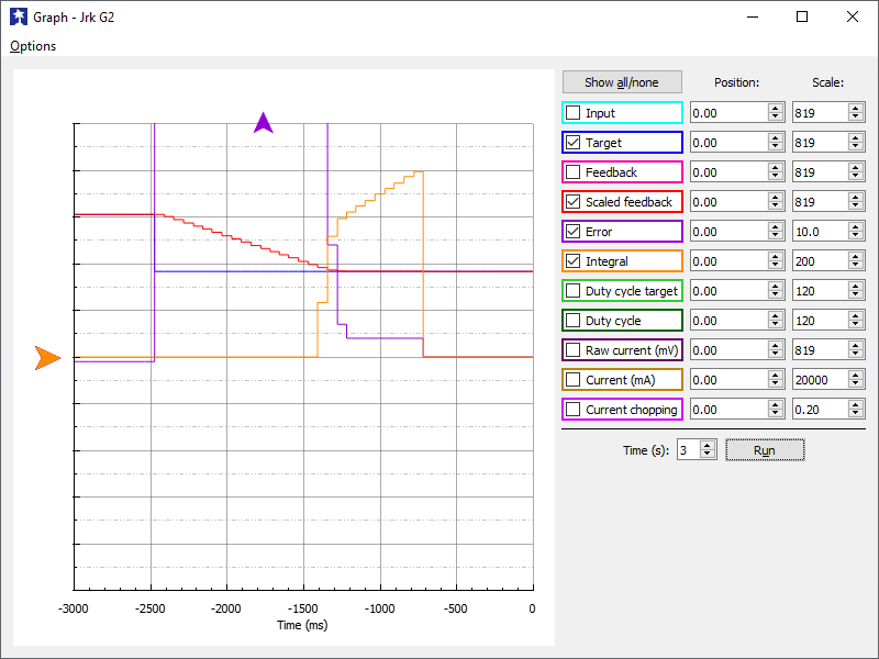 |
- Note how close your system gets to an error of zero using just the proportional term. You can use the integral term to get it much lower: with the integral limit set at 1000, try increasing the Integral coefficient until you see a correction that brings the error closer to zero. In the graph window shown here, you can see that the proportional term gets the error down to about 4, then the integral term builds up and, half a second later, moves the motor just a bit, reducing the error to 0.
- For systems that have a lot of friction relative to external forces, enable a “Feedback dead zone” so that the integral term doesn’t cause a slow oscillation very close to an error of zero. Watch how the integral term and duty cycle build up over time to achieve this. In this example, if the first adjustment had only reduced the error to 1, we might have considered setting a dead zone of 2 to prevent the integral term from continuing to build up at a slower rate.
- Enable the “Reset integral when proportional term exceeds max duty cycle” option to prevent the integral from winding up during large motions. This is also shown in the graph: the integral term does not start increasing until the error is close to zero.
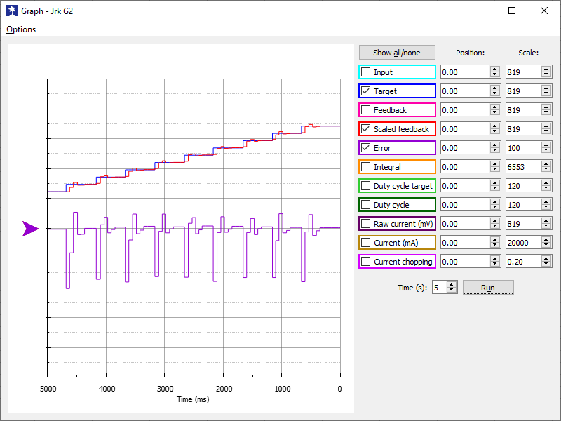 |
- Have your system take large steps (for example, by clicking the bar area of the Input tab scrollbar to move the target by 200) and use the graph to examine whether it consistently overshoots (the error crosses zero before coming to a stop and moving back) or undershoots (the error does not reach zero before slowing down). The graph window shown here, drawn for a system using a Derivative coefficient of zero, shows clear overshooting. In this example, the error actually oscillates back and forth several times before settling down.
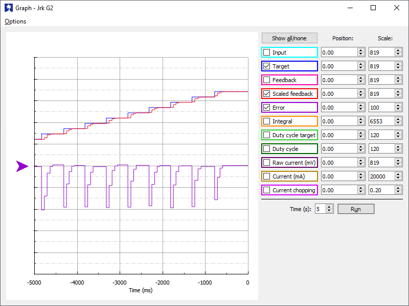 |
- Increase the Derivative coefficient to get rid of any overshooting, but not so much that it undershoots. The graph window shown here demonstrates undershooting, using a Derivative coefficient of 25. You can see that the error does not quickly reach zero. Instead, it gradually approaches zero after each step.
- Experiment with your system. Adjust any parameters as necessary to get the behavior that you need.
The following example plot shows a well-tuned system, with Proportional, Integral, and Derivative coefficients of 6.0, 0.25, and 12. When taking steps, the system stops very quickly at a position with very small error, only overshooting or undershooting by a small amount.
 |
Related products


Home | Forum | Blog | Support | Ordering Information | Lists | Distributors | BIG Order Form | About | Contact
© 2001–2026 Pololu Corporation
