Pololu Blog »
Pololu Blog (Page 27)
Welcome to the Pololu Blog, where we provide updates about what we and our customers are doing and thinking about. This blog used to be Pololu president Jan Malášek’s Engage Your Brain blog; you can view just those posts here.
Popular tags: community projects new products raspberry pi arduino more…
New product: Dual G2 High-Power Motor Drivers
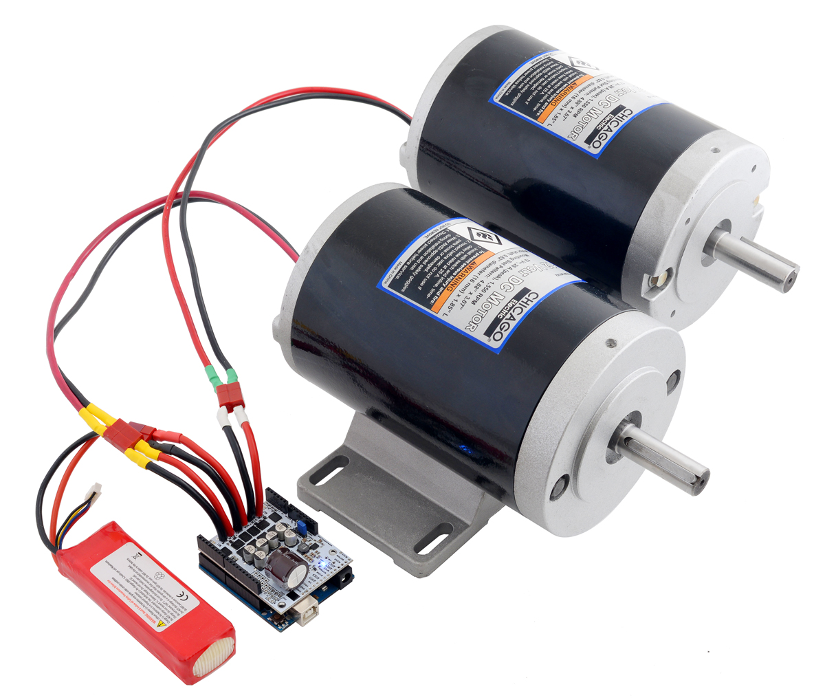 |
We sell a lot of motor drivers, which makes sense since you usually need motors to build robots, and motor drivers tend to be the kind of product you cannot really build yourself on a breadboard. One of our more popular products is the dual VNH5019 shield for the Arduino:
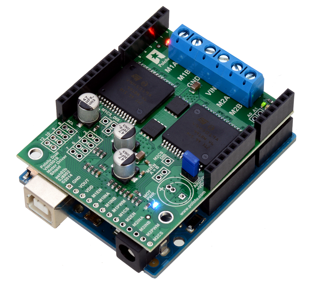 |
Pololu dual VNH5019 motor driver shield, assembled and connected to an Arduino Uno R3. |
|---|
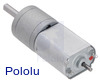
That product is based on ST’s massive VNH5019 motor driver chip, which is a successor to the VNH3SP30 driver we initially started selling back in 2005:
 |
Older version of the High-Current Motor Driver Carrier. |
|---|
When I first heard of the chip (at one of the first LVBots meetings), it seemed like someone must have misremembered the spec since it was inconceivable for a single integrated chip to deliver 30 amps. And to some extent, that was valid—you would have to do a lot of extra thermal management work to get 30 A out of that chip without it overheating. But the chip really could do in excess of 10 A, which was still amazing; the real limitation was in voltage, especially if you tried to use PWM at any moderate frequency. The VNH2SP30 was better about PWM frequency, letting us get to 20 kHz, but it had an upper operating limit of 16 V. The VNH5019 raised this to 24 V, getting us tantalizingly close to the 24V rail many would like to use. The problem is that 24 V is the limit, and we really need to be able to operate higher than that to account for the usual variations in nominally 24V power setups.
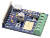
As far as I know, there is no integrated circuit that can deliver over ten amps at 24 V nominal (i.e. at least 30 V max); for that kind of power, you need to go to H-bridges with discrete MOSFETs. We have had those as stand-alone products for a while, too. But those still leave you with a lot of wiring to do if you want to drive two motors, which is typically the minimum for a mobile robot. The new product family we just released makes that easy by providing two high-power motor drivers in one Arduino shield-type package:
|
|

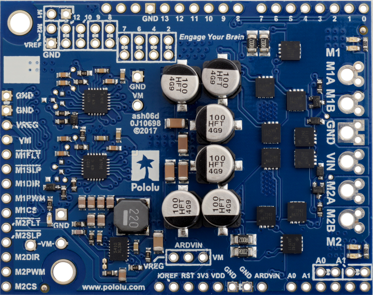
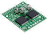
As you can see from the pictures, the main difference in these Dual G2 High-Power Motor Driver Shields is in the MOSFETs: the white boards have larger, 5×6mm MOSFETs, and the blue boards have smaller, 3×3mm MOSFETs. These correspond to the two versions of the individual drivers:
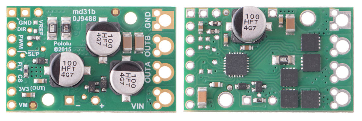 |
Pololu G2 High-Power Motor Drivers |
|---|
(The higher-power version on the left has the MOSFETs on the back side of the board.) We also offer each board with 30V and 40V MOSFETs, for four total options. The new dual motor drivers perform similarly to our single-channel G2 units, and like the single channel carriers, all of these dual drivers feature current sensing and an adjustable current limit that could be used to detect and protect against stall conditions. These are the individual performance points:
 Dual G2 High- Power Motor Driver 18v22 Shield |
 Dual G2 High- Power Motor Driver 18v18 Shield |
 Dual G2 High- Power Motor Driver 24v18 Shield |
 Dual G2 High- Power Motor Driver 24v14 Shield |
|
|---|---|---|---|---|
| Absolute max input voltage: |
30 V | 40 V | ||
| Max nominal battery voltage: |
18 V | 28 V | ||
| Max continuous current per channel: |
22 A | 18 A | 18 A | 14 A |
| Default active current- limiting threshold: |
60 A | 50 A | 40 A | |
| Current sense output: |
10 mV/A | 20 mV/A | ||
For drivers like these, power (heat) dissipation is generally the limiting factor. The copper area around the MOSFETs on both the white and blue versions of the drivers are about the same, so the lower-current blue units perform better then their smaller single channel G2 counter-parts, while the higher current white drivers do worse than the smaller single channel G2 carriers (which also use four layer PCBs for better performance). The power ratings we provide are the maximums without additional heat sinking or air flow and at room temperature. Please note that the boards will be extremely hot at those maximum currents, and the available current will be lower if the ambient temperature is higher.
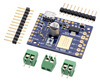
Since many Arduino boards do not support higher input voltages, the new dual drivers also incorporate a 1A switching regulator so that a single higher-voltage supply can power the motors and Arduino. We have an Arduino library to help you get up and running quickly. And for those who want to use the board without an Arduino, all of the motor control connections are also brought out to a row of 0.1″ headers on one side of the board.
(And for those of you wanting to use this kind of driver with a Raspberry Pi, we have a Raspberry Pi HAT form-factor version coming soon!)
Related products


New product: P-Star 45K50 Mini SV
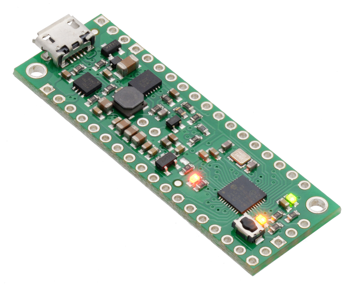 |
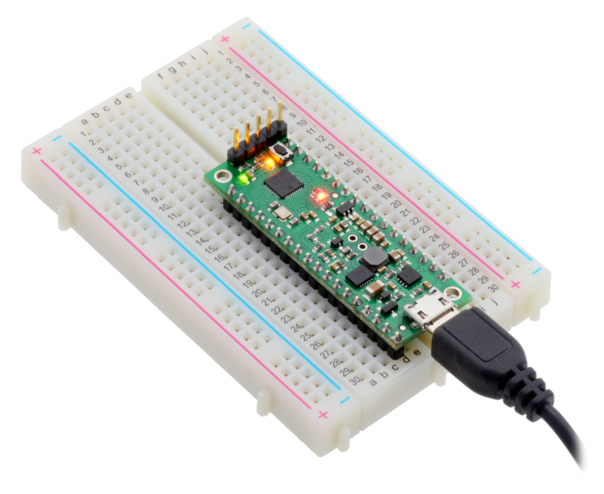
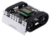
I am excited to announce our new product, the Pololu P-Star 45K50 Mini SV, which is the second member of our P-Star family of programmable controllers based on the PIC18 microcontrollers from Microchip. The P-Star 45K50 Mini SV features a user-programmable PIC18F45K50 microcontroller (32 KB of flash, 2 KB of RAM, full-speed USB), a USB bootloader, and a switching step-down regulator that allows it to be powered from 5 V to 36 V.
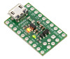
The P-Star 45K50 Mini SV is very similar to the smaller P-Star 25K50 Micro, but is bigger and better, with 11 more I/O pins (for a total of 30), a more capable 5 V regulator, and several other additional features. The table below lists the main differences between the two P-Stars:
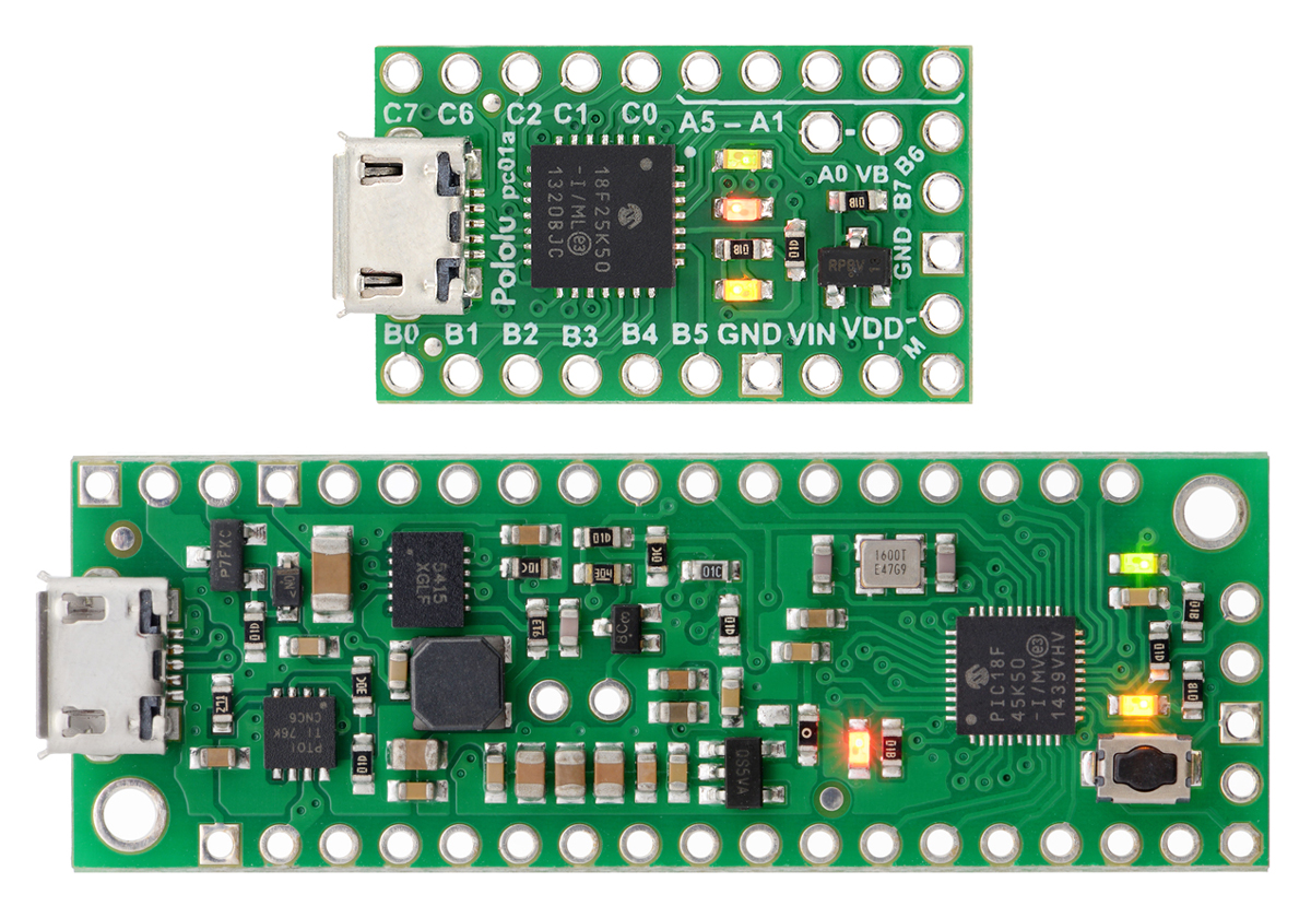 |
P-Star 25K50 Micro (top) and P-Star 45K50 Mini SV (bottom). |
|---|
 |
 | |
| P-Star 25K50 Micro | P-Star 45K50 Mini SV | |
|---|---|---|
| Microcontroller: | PIC18F25K50 | PIC18F45K50 |
| User I/O lines: | 19 | 30 |
| Analog inputs: | 14 | 25 |
| Reset button: |  |
|
| Operating voltage: | 5.5 V to 15 V | 5 V to 36 V |
| Regulator type: | linear | switching step-down |
| Regulated current:(1) | 100 mA | 500 mA |
| Auxiliary 3.3 V regulator: | |
|
| Dimensions: | 1″ × 0.6″ | 2.0″ × 0.7″ |
1 These values are rough approximations for comparison purposes. Available current depends on input voltage, current consumed by the board, ambient conditions, and regulator topology.
Although we have been using PIC microcontrollers since our very first product, these two P-Stars are our first products where the PIC microcontroller can be programmed by the user. You can program the P-Star in C or assembly with the MPLAB X IDE, or you can use Microchip’s new online IDE, MPLAB Xpress. The P-Star User’s Guide has instructions for getting started with those environments.
You can load programs onto the P-Star via its proprietary USB bootloader using our open source software that is available for Windows, Linux, and Mac. The bootloader uses 8 KB of flash memory, leaving 24 KB for the user. Alternatively, an ICSP programmer can erase the bootloader and access the full 32 KB of program memory. (Since the bootloader is not recoverable, we recommend this option only for those who are comfortable programming exclusively with an external programmer.)
Both P-Star boards feature a precision 16 MHz crystal, a USB Micro-B connector, and three user-controllable LEDs. A voltage regulator and power selection circuit allow the board to be powered from either USB or an external voltage source.
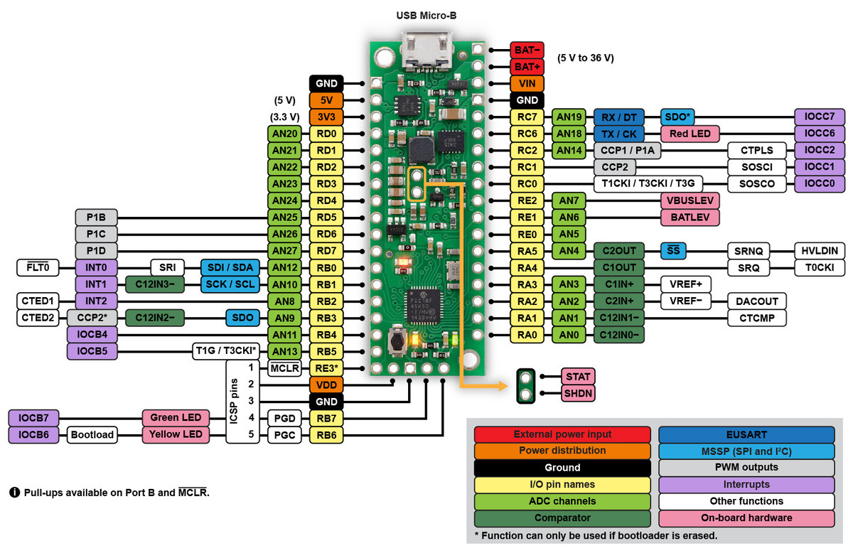 |
P-Star 45K50 Mini SV pinout diagram. |
|---|
Compared to the popular ATmega32U4 microcontroller, the PIC18F25K50 and PIC18F45K50 have nearly the same performance and memory capacity, but these PICs also have some compelling features that are missing on the AVR. For example, they use the PIC18 architecture, which has two interrupt priority levels: interrupts can be assigned to either level, and a high-priority interrupt routine can run during a low-priority one. This powerful feature is what enables our Maestro servo controllers to generate precise servo signals while still using low-priority interrupts to assist with serial communication and other tasks. Unlike the ATmega32U4, these PICs can operate at full speed down to 2.7 V (though the brown-out reset on the P-Star is activated at 2.85 V by default).
|
|
The PIC18F25K50 and PIC18F45K50 also feature a 5-bit digital-to-analog converter (DAC), which is a handy feature not available on many 8-bit microcontrollers. We use that DAC to set the stepper motor current limit on our Tic stepper controllers, where the PIC18F25K50 serves as the main processor.
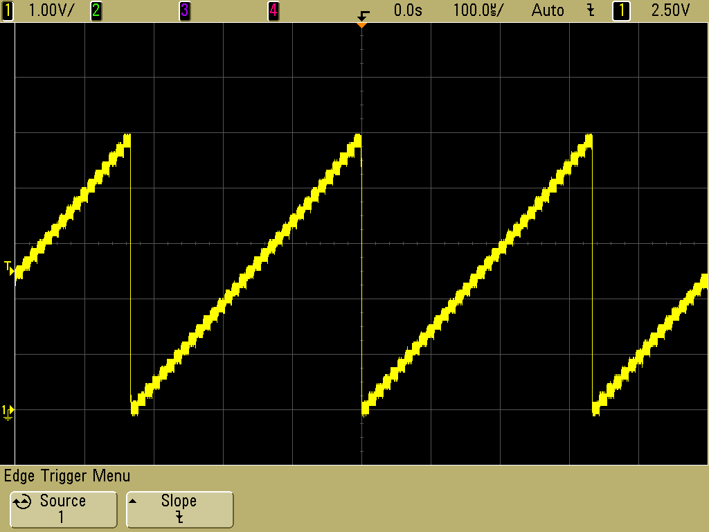 |
A 3 kHz triangle wave generated by the 5-bit digital-to-analog converter (DAC) on the P-Star 25K50 Micro. |
|---|
For more information, check out the P-Star 45K50 Mini SV page.
Related products


New product: Tic T834 USB Multi-Interface Stepper Motor Controller
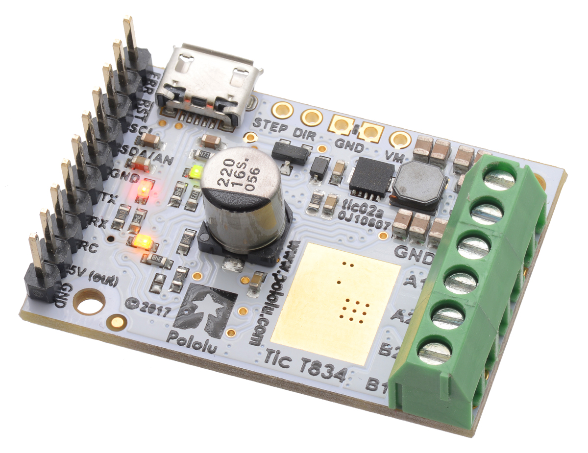 |
I am excited to announce our new product, the Tic T834 USB Multi-Interface Stepper Motor Controller. The Tic T834 is the second member of the Tic family of USB stepper motor controllers. It incorporates a TI DRV8834 driver, can operate from 2.5 V to 10.8 V, and can deliver up to approximately 1.5 A per phase without a heat sink or forced air flow.
Like the Tic T825, the Tic T834 makes basic speed or position control of a stepper motor easy, with support for six high-level control interfaces:
- USB for direct connection to a computer
- TTL serial operating at 5 V for use with a microcontroller
- I²C for use with a microcontroller
- RC hobby servo pulses for use in an RC system
- Analog voltage for use with a potentiometer or analog joystick
- Quadrature encoder input for use with a rotary encoder dial, allowing full rotation without limits (not for position feedback)
 |
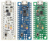
Tic T825 and T834 USB Multi-Interface Stepper Motor Controllers. |
|---|
The Tic T834 is available with connectors soldered in or without connectors soldered in.
Related products


Free shipping, phase two: lots more free shipping
 |
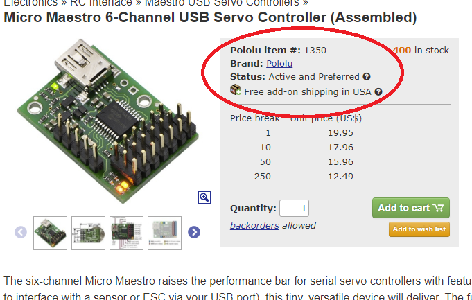
We are now offering free US shipping for $60 or more of Pololu-branded products with active statuses. |
|---|
Since my post on Thursday afternoon, we have brought free shipping to dozens of products and free add-on shipping to hundreds more. Unfortunately, that still does not get you really free shipping for most of our thousands of products because many of them are individually too low-cost to make part-by-part free shipping feasible. We just do not have a way to ship you a $6 regulator or an $8 pair of wheels for free without having to inflate the price of the products. But today, we released phase two of our free shipping initiative, which allows us to offer free shipping in the US on orders of $60 or more of Pololu-branded products that have an active status. This should bring free shipping to most of our typical orders, which might include that set of wheels, a few motors, a motor driver, and maybe the $6 regulator.
You might be wondering what I meant by that somewhat awkward phrase, “Pololu-branded products that have an active status”. That’s actually related to yet another exciting new set of features we are bringing to the Pololu site. We are proud that we design and manufacture most of our products, and we want to make it easy to tell which items are made by us. For products from other brands, especially where we are authorized distributors or otherwise working with those brands, we want to make it clear that you are getting the product from that brand, and not some counterfeit or knock off. And sometimes we all just want something generic, like the ubiquitous 0.1" headers, where the manufacturer or brand does not really matter. In some of those cases, we might not want to reveal our suppliers, or we might want to have the flexibility to change suppliers without updating product specifications; explicitly calling out a product as generic should help make it clear what kind of a product you are getting.
Because many of our customers build their own products using our products as components, or design curricula around our products, I also want to better communicate the life cycle status of our products. We therefore added a “product status” field to our product listings so that you can quickly tell if a product is one that we expect to keep making for a long time or if we expect to be discontinuing it soon. I will go over the various product status designations in a separate blog post, but for the purposes of this free shipping announcement, the point is that the products we make and which are in our good graces will be considered toward the $60 free shipping minimum.
 |
We will be updating the product brand and status fields for our products in the coming weeks; please let us know if a product you are interested in is not updated yet.
Happy Halloween!
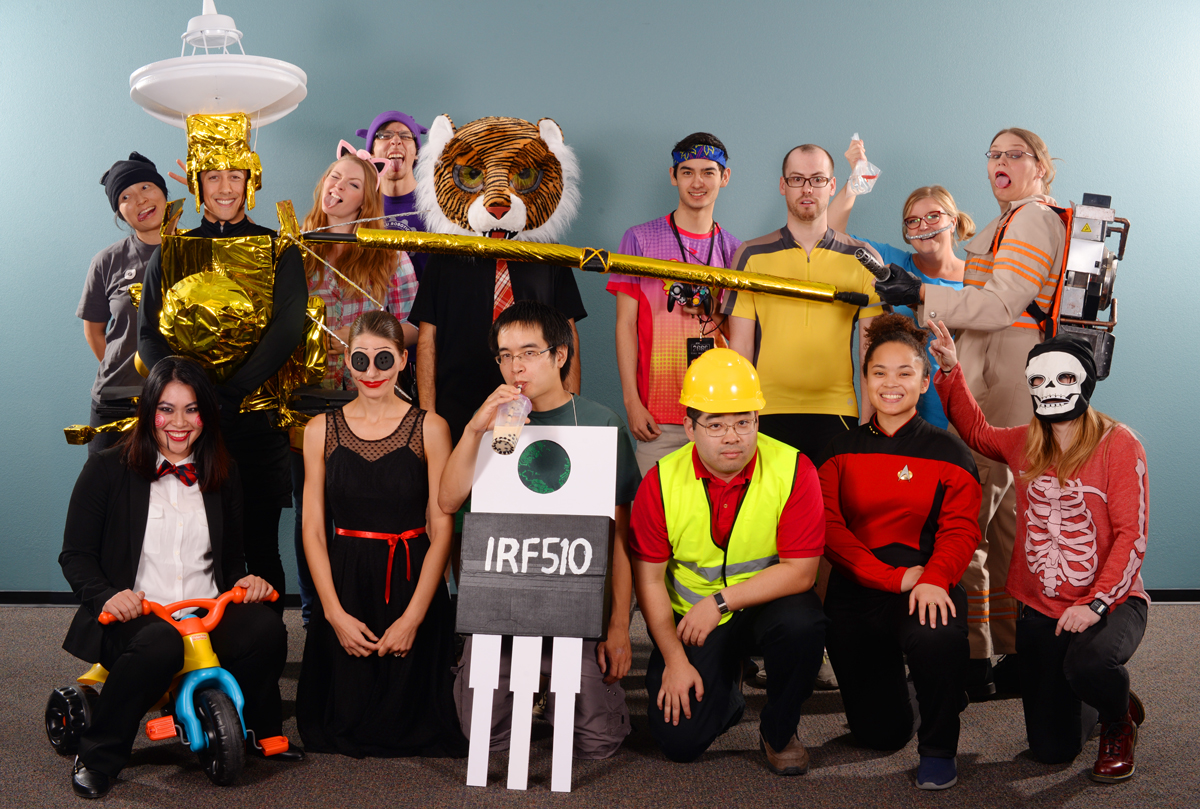 |
Another Halloween means another batch of great costumes from the people at Pololu!
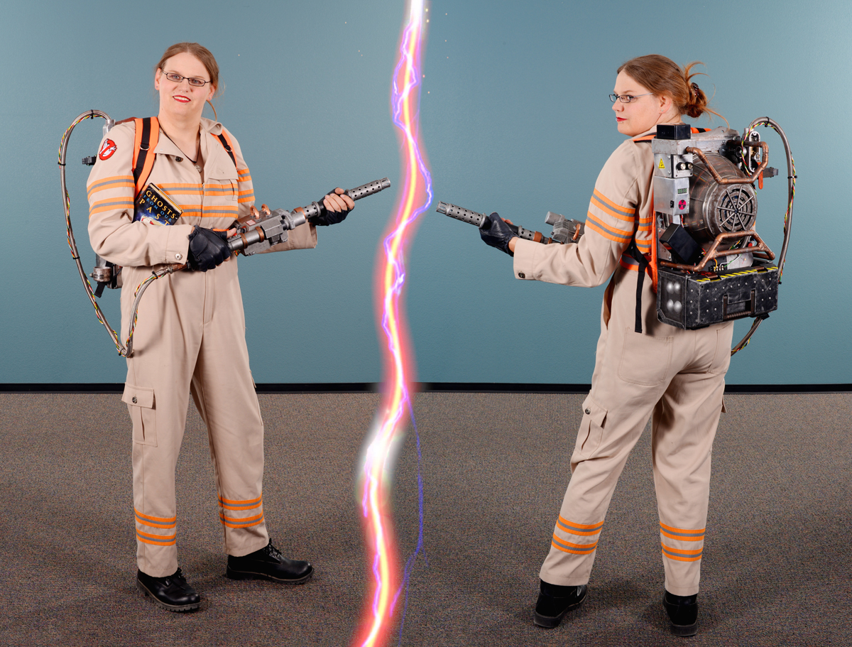
Highlights from this year include Jennifer’s impressively detailed Ghostbuster costume, complete with a “working” proton pack (well, at least the lights worked) built around some laser-cut parts…
 |
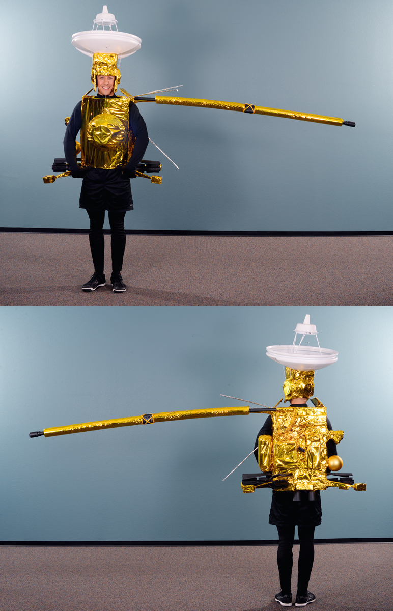
and Jon’s elaborate representation of the Cassini-Huygens spacecraft, which included an actual magnetometer on the tip of his boom and a buzzer to audibly indicate magnetic measurements.
 |
Did you use any Pololu products in your Halloween costume or decorations? We’d love to hear about it on our forum or in the comments below, and we might even feature it in a future blog post!
Have a Happy Halloween!
New 20D gearmotors available with 12 V windings and with long-life carbon brushes
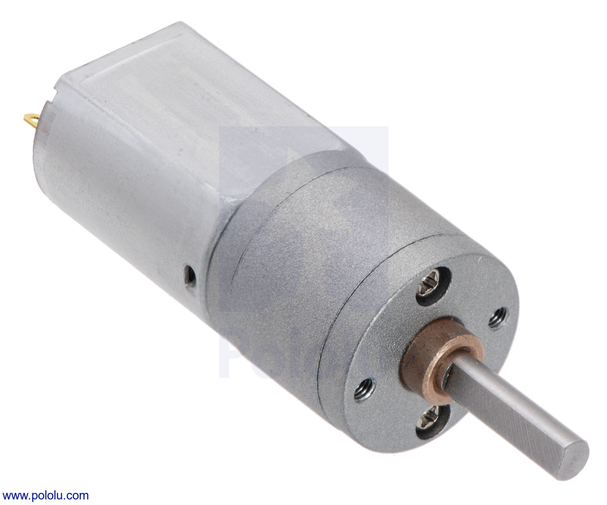 |
We love motors here at Pololu, and we are committed to offering you the best selection so that you can find just the right drive solution for your project. Our latest efforts have gone into expanding our selection of 20D gearmotors to include 12 V versions, which have approximately the same performance at 12 V as our 6 V versions do at 6 V, just with half the current draw. This in turn enables the use of lower-current (and typically lower-cost) motor drivers in applications with access to higher voltages.
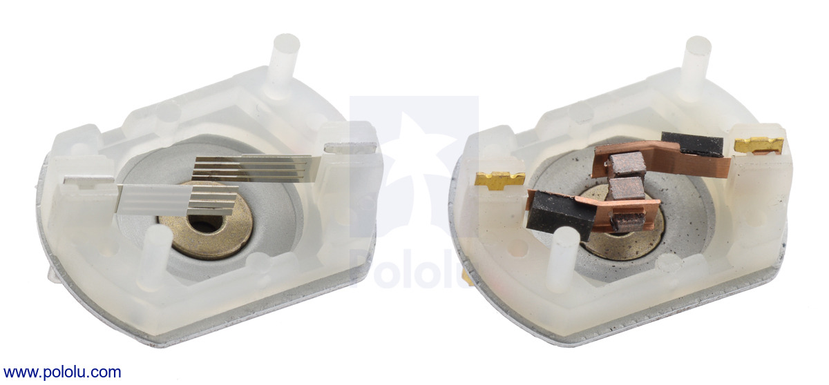
Additionally, we noticed that our original 6 V versions do not last as long as we would like in some applications, so we made these new 12 V versions with long-life carbon brushes instead of precious metal brushes, and we released new versions of our 6 V motors with long-life carbon brushes as well. These versions have “CB” in their names, and they can be differentiated from versions with precious metal brushes by their copper-colored terminals.
 |
 |
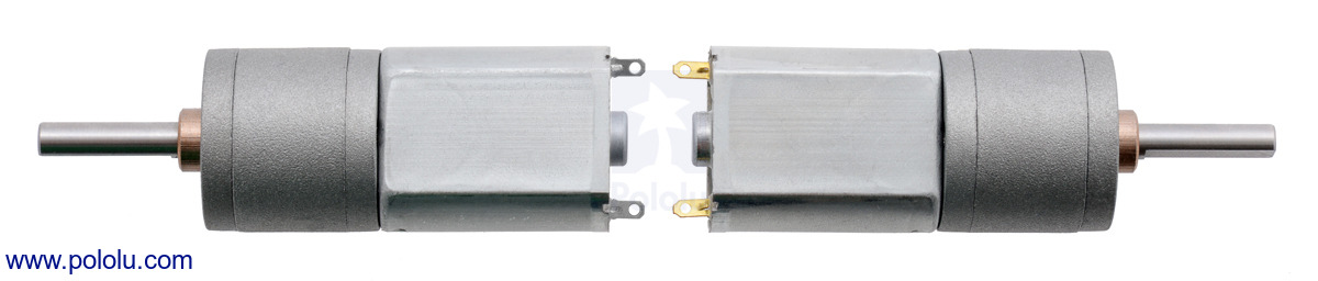
20D mm metal gearmotor precious metal brushes (left) next to 20D 6V CB and 12V CB long-life carbon brushes. |
|---|
Please note that making the brushes more robust can just move the failure point to the windings or gears if you try to push the motors too hard, but if you use them around their nominal voltages and keep the continuous load low (under around 20% of the stall torque or 1 kg-cm, whichever is lower), the carbon brushes allow the motors to last several times longer than versions with precious metal brushes.
Changing the brushes does affect the performance in ways beyond lifetime (e.g. the starting voltage is generally a little higher with the carbon brushes), so we are continuing to offer precious metal versions of our 6 V motors for now, but we might phase those out in the future. Please contact us or post a comment below if continued availability of the precious metal versions is important to you.
Currently, only the 6V versions with precious metal brushes are available with a rear motor shaft that can be used to add an encoder, like our magnetic encoder for 20D mm metal gearmotors, but the 6V CB and 12V CB motors should be available with this rear shaft option by the end of November.
With the addition of these new units, our selection of 20D gearmotors now spans nearly fifty options:
| Rated Voltage |
Brush Type | Stall Current @ Rated Voltage |
No-Load Speed @ Rated Voltage |
Approximate Stall Torque @ Rated Voltage |
 Single-Shaft (Gearbox Only) |
 Dual-Shaft (Gearbox & Motor) |
|---|---|---|---|---|---|---|
| 12 V | long-life carbon (CB) |
1.6 A | 570 RPM | 26 oz-in | 25:1 12V CB | |
| 450 RPM | 33 oz-in | 31:1 12V CB | ||||
| 225 RPM | 58 oz-in | 63:1 12V CB | ||||
| 180 RPM | 75 oz-in | 78:1 12V CB | ||||
| 140 RPM | 85 oz-in | 100:1 12V CB | ||||
| 110 RPM | 110 oz-in | 125:1 12V CB | ||||
| 90 RPM | 130 oz-in | 156:1 12V CB | ||||
| 72 RPM | 160 oz-in | 195:1 12V CB | ||||
| 57 RPM | 200 oz-in | 250:1 12V CB | ||||
| 45 RPM | 250 oz-in | 313:1 12V CB | ||||
| 36 RPM | 290 oz-in | 391:1 12V CB | ||||
| 29 RPM | 350 oz-in | 488:1 12V CB | ||||
| 6 V | long-life carbon (CB) |
2.9 A | 590 RPM | 22 oz-in | 25:1 6V CB | |
| 470 RPM | 28 oz-in | 31:1 6V CB | ||||
| 230 RPM | 54 oz-in | 63:1 6V CB | ||||
| 190 RPM | 62 oz-in | 78:1 6V CB | ||||
| 150 RPM | 72 oz-in | 100:1 6V CB | ||||
| 120 RPM | 87 oz-in | 125:1 6V CB | ||||
| 93 RPM | 110 oz-in | 156:1 6V CB | ||||
| 75 RPM | 130 oz-in | 195:1 6V CB | ||||
| 60 RPM | 170 oz-in | 250:1 6V CB | ||||
| 46 RPM | 220 oz-in | 313:1 6V CB | ||||
| 37 RPM | 260 oz-in | 391:1 6V CB | ||||
| 30 RPM | 310 oz-in | 488:1 6V CB | ||||
| 6 V | precious metal |
2.9 A | 590 RPM | 22 oz-in | 25:1 6V | 25:1 6V dual-shaft |
| 470 RPM | 28 oz-in | 31:1 6V | 31:1 6V dual-shaft | |||
| 230 RPM | 54 oz-in | 63:1 6V | 63:1 6V dual-shaft | |||
| 190 RPM | 62 oz-in | 78:1 6V | 78:1 6V dual-shaft | |||
| 150 RPM | 72 oz-in | 100:1 6V | 100:1 6V dual-shaft | |||
| 120 RPM | 87 oz-in | 125:1 6V | 125:1 6V dual-shaft | |||
| 93 RPM | 110 oz-in | 156:1 6V | 156:1 6V dual-shaft | |||
| 75 RPM | 130 oz-in | 195:1 6V | 195:1 6V dual-shaft | |||
| 60 RPM | 170 oz-in | 250:1 6V | 250:1 6V dual-shaft | |||
| 46 RPM | 220 oz-in | 313:1 6V | 313:1 6V dual-shaft | |||
| 37 RPM | 260 oz-in | 391:1 6V | 391:1 6V dual-shaft | |||
| 30 RPM | 310 oz-in | 488:1 6V | 488:1 6V dual-shaft | |||
Note: Stalling or overloading gearmotors can greatly decrease their lifetimes and even result in immediate damage. In order to avoid damaging the gearbox, we recommend keeping continuously applied loads under 50 oz-in (3.5 kg*cm) for the versions with precious metal brushes and under 70 oz-in (5 kg-cm) for the versions with carbon brushes (the ones with “CB” in the name). Stalls can also result in rapid (potentially on the order of a second) thermal damage to the motor windings and brushes, especially for motors like this that can deliver a lot of power for their size; a general recommendation for brushed DC motors is to limit continuous current to approximately 25% of the stall current.
Rolling out free shipping at Pololu
 |
Everyone wants free shipping, right? Well, today I am happy to announce an important step in bringing free shipping to Pololu, at least for our US customers. We are beginning to offer free shipping in these two senses:
Free shipping within the United States
 |
Some items are eligible for free shipping within the United States. If your shopping cart consists only of items eligible for free shipping, you will be presented with a “Free Shipping” shipping option during checkout. Free shipping will be shipped by a carrier and service we select, which will typically be the lowest-cost, slowest service. Currently, that would likely be First-Class Mail through the US Post Office or a ground service by FedEx, depending on the contents of the order.
Free add-on shipping within the United States
 |
Some items are eligible for free add-on shipping for orders within the United States. These are typically very light items that should not significantly impact our shipping cost, and we pass on those savings to you. No additional shipping will be charged for these items, independent of your shipping method. Orders that consist only of free add-on shipping items will cost the minimum shipping cost for each service as the item sizes and weights will not be added to the shipping cost calculation. Orders with at least one free shipping item and the rest free add-on shipping items will have a free shipping option.
Because items with free add-on shipping will not be considered in the calculation, it is possible for the shipping method you select to be invalid because the package exceeds the limit for that method. In such cases, we will substitute a similar shipping method. For example, if you pay for First-Class Mail as your shipping method but your order actually ends up weighing more than the limit for First Class Mail, we would ship by Priority Mail.
By controlling these two aspects of free shipping on an individual product level, we can really offer free shipping, without raising prices. We are rolling this feature out with a few items we would like to promote:
Products initially eligible for free shipping and free add-on shipping:
|
Pololu Dual VNH5019 Motor Driver Shield for Arduino |
|
|
Tic T825 USB Multi-Interface Stepper Motor Controller (Connectors Soldered) |
|
|
Tic T825 USB Multi-Interface Stepper Motor Controller |
Products initially eligible for free shipping only:
|
Zumo 32U4 Robot (Assembled with 50:1 HP Motors)Zumo 32U4 Robot (Assembled with 75:1 HP Motors)Zumo 32U4 Robot (Assembled with 100:1 HP Motors) |
Products initially eligible for free add-on shipping only:
As we work on our system and monitor the results with these initial products, my goal is to make free shipping, or at least incrementally free shipping, available for more and more of our products. We still do not have a solution for those of you who write us angry emails about the ridiculousness of our charging $3.95 to ship a $2 part (and yes, I am aware of 39-cent listings with free shipping on AliExpress; for now, we cannot compete with them on price alone). But rest assured that since shipping is one of our biggest expenses, we will continue to work hard on keeping that cost as low as we can.
If you see a product that you feel should qualify for free shipping or free add-on shipping but does not, please contact us, and we can evaluate the product’s eligibility. I would also like to hear what you think of this approach and whether you expect it will be helpful to you.
Update (31 October 2017): We are now offering lots more free shipping.
Parallax Boe-Bot Robot Kit - USB
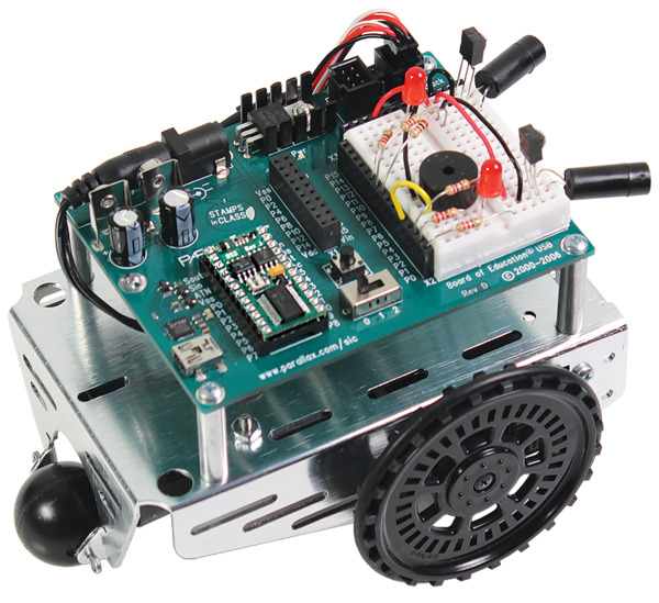 |
We are now carrying the Parallax Boe-Bot Robot Kit - USB, which incorporates a USB-to-serial adapter into the board, so it does not require a separate serial adapter.
The Boe-Bot Robot Kit is an educational kit complete with parts and a textbook for building and programming your own robot. No previous robotics, electronics, or programming experience is required; the kit does not require soldering.
Related products

Free Circuit Cellar magazine October 2017
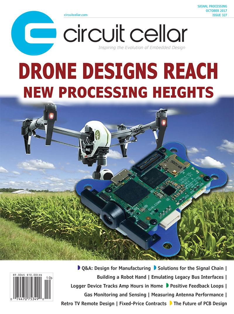 |
Get a FREE copy of Circuit Cellar magazine’s October 2017 issue issue with your order, while supplies last. To get your free issue, enter the coupon code CIRCUIT1017 to your shopping cart, or click the link. The magazine will add 6 ounces to your order weight when calculating your shipping options.
For back issues and more information, see our free Circuit Cellar magazine offers.
Related products

Aerial photography kite rig
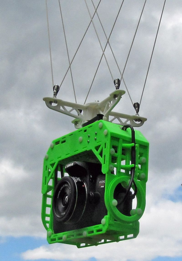 |
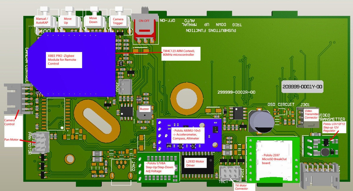
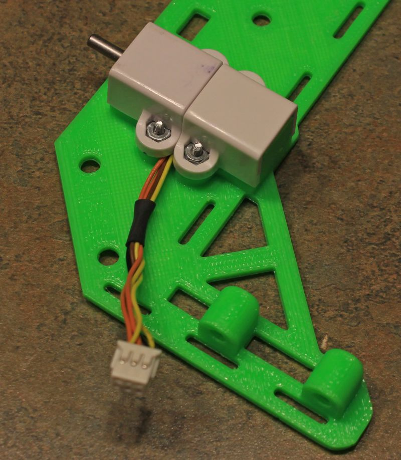
Pololu customer Yvon Hache made this 3D-printed aerial photography rig that he shared in a forum post. The rig, trailing 100 feet below the kite, automatically triggers a camera to take pictures at three tilt angles and sixteen pan angles. It incorporates an ARM Cortex-M4 microcontroller from Texas Instruments (32-bit, 80 MHz, TM4C123GH6PZ), an AltIMU-10 v5, Pololu voltage regulators, and a Zigbee module for wireless remote control. Yvon uses a pair of Pololu micro metal gearmotor extended brackets per motor—one mounts the motor to the frame and the other protects the encoder assembly.
|
|
More kite rig information and pictures can be found on Yvon’s website.
Related products

|
298:1 Micro Metal Gearmotor HPCB 6V with Extended Motor Shaft |

|
Magnetic Encoder Pair Kit for Micro Metal Gearmotors, 12 CPR, 2.7-18V |

|
Pololu Micro Metal Gearmotor Bracket Extended Pair |

|
Pololu 12V Step-Up Voltage Regulator U3V12F12 |

|
Pololu Adjustable Step-Up/Step-Down Voltage Regulator S7V8A |

|
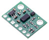
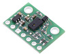
AltIMU-10 v5 Gyro, Accelerometer, Compass, and Altimeter (LSM6DS33, LIS3MDL, and LPS25H Carrier) |

|
Breakout Board for microSD Card |


Home | Forum | Blog | Support | Ordering Information | Lists | Distributors | BIG Order Form | About | Contact
© 2001–2026 Pololu Corporation


