Development Boards (Programmable Controllers) » Raspberry Pi » Raspberry Pi Expansion Boards »
Dual TB9051FTG Motor Driver for Raspberry Pi (Assembled)

This add-on board enables a Raspberry Pi B+, Pi A+, Pi 2 or Pi 3 to drive a pair of brushed DC motors. Its dual TB9051FTG motor drivers operate from 4.5 V to 28 V and can deliver a continuous 2.6 A (5 A peak) per motor. The default pin mappings make it easy to get started using our provided software, but the board also exposes most of the driver chips’ I/O pins for more specialized applications. This version ships fully assembled with connectors soldered in.
Alternatives available with variations in these parameter(s): partial kit? Select variant…
 Compare all products in Raspberry Pi Expansion Boards or Brushed DC Motor Drivers.
| Description | Specs (14) | Pictures (11) | Resources (7) | FAQs (0) | On the blog (1) | Distributors (43) |
|---|
Overview
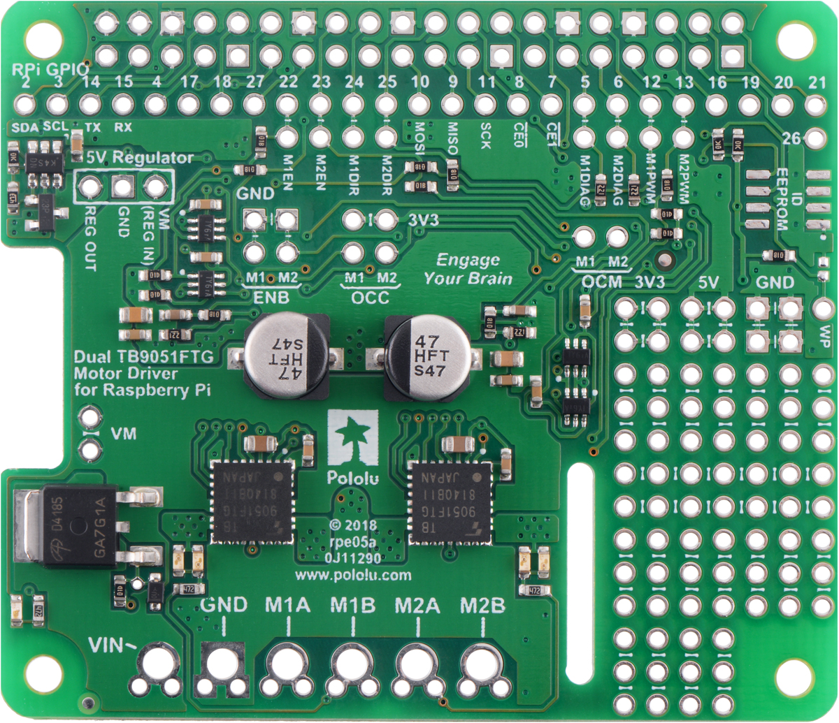 |
This motor driver expansion board and its corresponding Python library make it easy to control a pair of bidirectional, brushed DC motors with a compatible Raspberry Pi (Model B+ or newer), including the Pi 3 Model B+ and Model A+. The expansion board uses a pair of Toshiba TB9051FTG motor drivers, which operate from 4.5 to 28 V and can deliver a continuous 2.6 A per channel (up to 5 A per channel for a few seconds). Other features include a reverse battery protection circuit and logic gates that reduce the number of I/O pins required to control the driver ICs effectively. It is available either as a partial kit, with a female header and terminal blocks included but not soldered in, or fully assembled with these connectors soldered to the PCB.
The board’s default configuration uses six GPIO pins to control the motor drivers, making use of the Raspberry Pi’s hardware PWM outputs, and it uses two additional pins to read status outputs from the drivers. However, the pin mappings can be customized if the defaults are not convenient, and other control inputs and outputs of the TB9051FTG ICs are accessible on the board for more advanced applications.
 |
The board matches the Raspberry Pi HAT (Hardware Attached on Top) mechanical specification, although it does not conform to the full HAT specifications due to the lack of an ID EEPROM. (A footprint for adding your own EEPROM is available for applications where one would be useful; pull-ups on SDA, SCL, and WP are provided.) It is not practical to use this expansion board with the original Raspberry Pi Model A or Model B due to differences in their pinout and form factor.
For controlling higher-power motors with a Raspberry Pi, consider our Dual G2 High-Power Motor Driver expansion boards, and for controlling lower-power motors with a smaller board, consider our DRV8835 dual motor driver or MAX14870 dual motor driver kits. We also have a similar dual TB9051FTG shield for Arduinos and Arduino-compatible boards and a basic single TB9051 carrier for those using a different controller or with tighter space constraints.
Features
- Dual-channel H-bridge motor driver in the form factor of a Raspberry Pi expansion board
- Wide operating voltage range: 4.5 V to 28 V
- Output current: 2.6 A continuous (5 A peak) per motor
- Automatic current chopping feature helps prevent overheating by gracefully reducing power rather than abruptly shutting down
- PWM operation up to 20 kHz, which is ultrasonic and allows for quieter motor operation
- Motor indicator LEDs show what the outputs are doing even when no motor is connected
- Board can optionally power the Raspberry Pi base through added regulator like the D24V10F5 or D24V22F5 (not included)
- Python library makes it easy to get started using this board as a motor driver expansion board
- GPIO pin mappings can be customized if the default mappings are not convenient
- Remaining motor driver pins are exposed for advanced use
- Exposed solderable ground pads below the driver ICs on the bottom of the PCB
- Reverse-voltage protection on motor supply
- Robust drivers:
- Transient operation (< 500 ms) up to 40 V
- Under-voltage lockout and protection against over-current/short-circuit and over-temperature
- Active-low error output indicates over-current, over-temperature, under-voltage, or VCC over-voltage condition
- Prototyping space for easier/cleaner construction of custom circuits
Details for item #2762
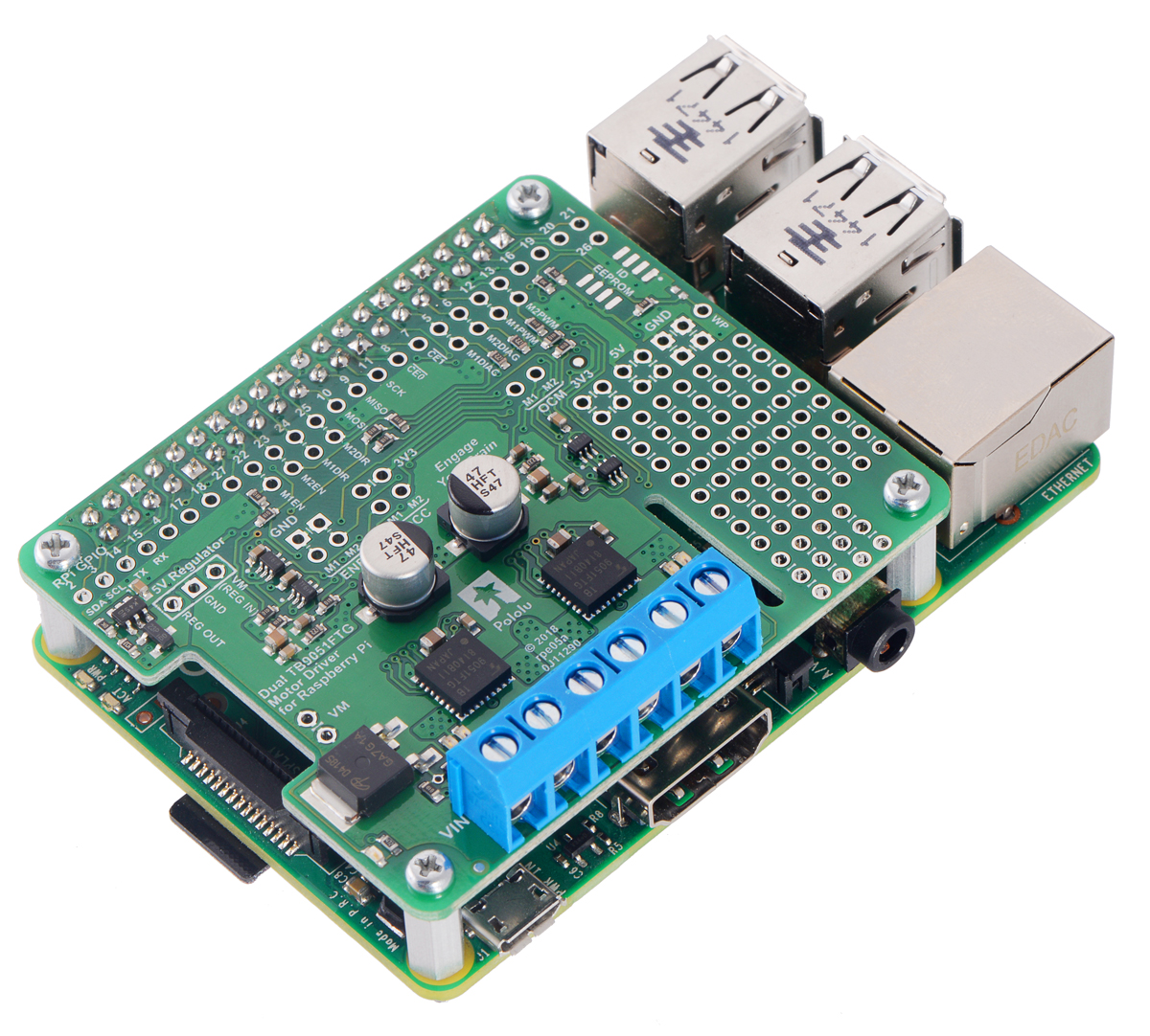
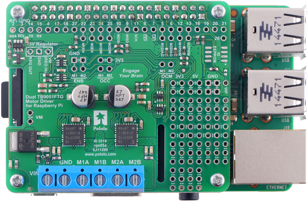
This version of the motor driver is fully assembled, with a 2×20-pin 0.1″ female header (for connecting to the Raspberry Pi’s 40-pin GPIO header) and a six-pin strip of 5 mm terminal blocks (for motor and power connections) soldered in. (See item #2761 for a kit version with connectors included but not soldered in.)
|
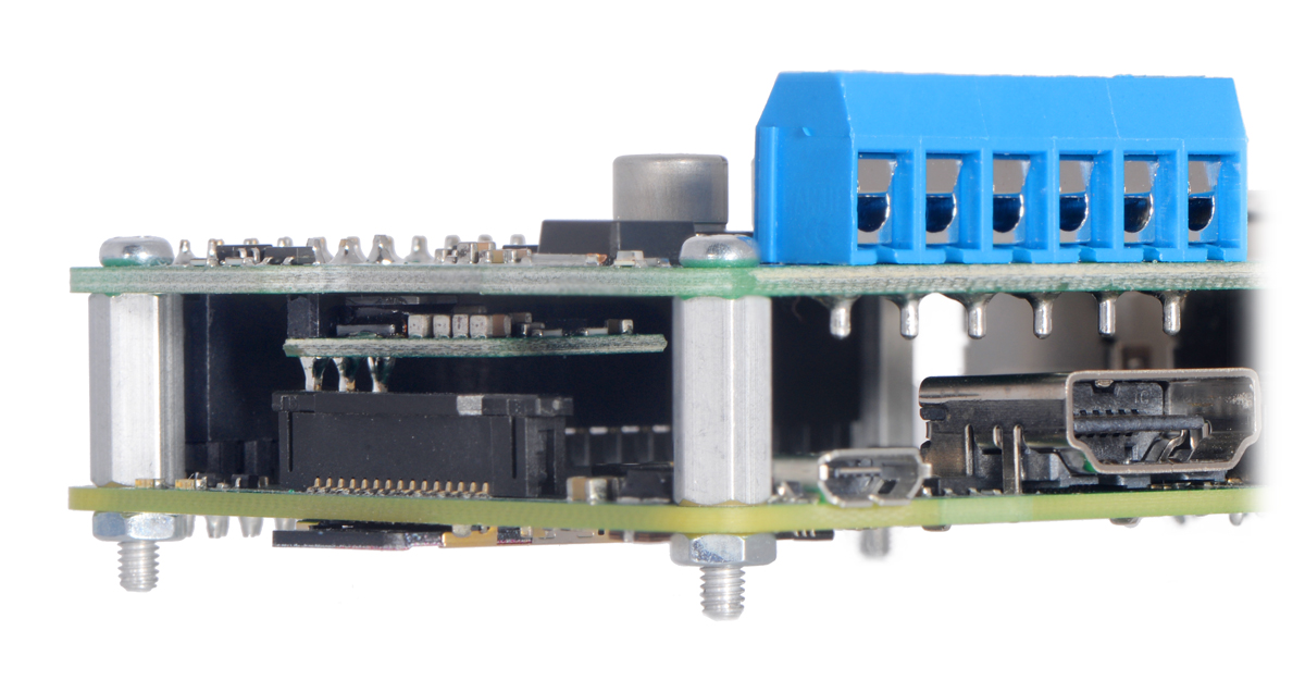
The motor driver ships with a set of four M2.5 standoffs (11 mm length), screws, and nuts that can be used to secure the board to the Raspberry Pi at the proper height for the GPIO connector. If you decide not to use the standoffs, be careful not to allow the motor and power connections to short against the Raspberry Pi’s HDMI connector.
Shorting blocks and 0.1″ male headers (not included) can be used to make some of the more advanced optional modifications to the board, such as remapping the control pins.
A Raspberry Pi is not included.
Using the motor driver board
This section explains how to use the dual TB9051FTG motor driver add-on board and provides some basic information about the motor driver pins to help get you started. However, we strongly encourage you to consult the TB9051FTG datasheet (2MB pdf) for detailed pin descriptions, truth tables, and electrical characteristics. This expansion board is essentially a breakout board for two TB9051FTG motor driver ICs with additional logic circuitry to simplify the motor control, so the datasheet is your best resource for answering questions not covered here.
 |
In the board’s default state, the motor driver outputs and the Raspberry Pi are powered separately, though they share a common ground. The board’s 3.3 V and 5 V logic supplies are provided by the Raspberry Pi. When used this way, the Raspberry Pi must be powered via its USB Micro-B receptacle, and the motor driver board must be supplied with 4.5 V to 28 V through its large VIN and GND pads. However, the motor driver board provides a set of three through-holes where you can conveniently connect an appropriate voltage regulator, allowing the motor supply to also power the Raspberry Pi (see the Powering the Raspberry Pi from the motor driver board section below).
A reverse-voltage protection circuit helps prevent damage to the board in case the motor power supply is connected backward. The reverse-protected input voltage can be accessed for use in other circuits through the two pins labeled VM on the left side of the board.
The board includes logic gates that enable drive/brake operation of the TB9051FTG drivers with only two control pins per motor (PWM and direction). As drive/brake operation usually provides a more linear relationship between PWM duty cycle and motor speed than drive/coast operation, we generally recommend using drive/brake operation when possible.
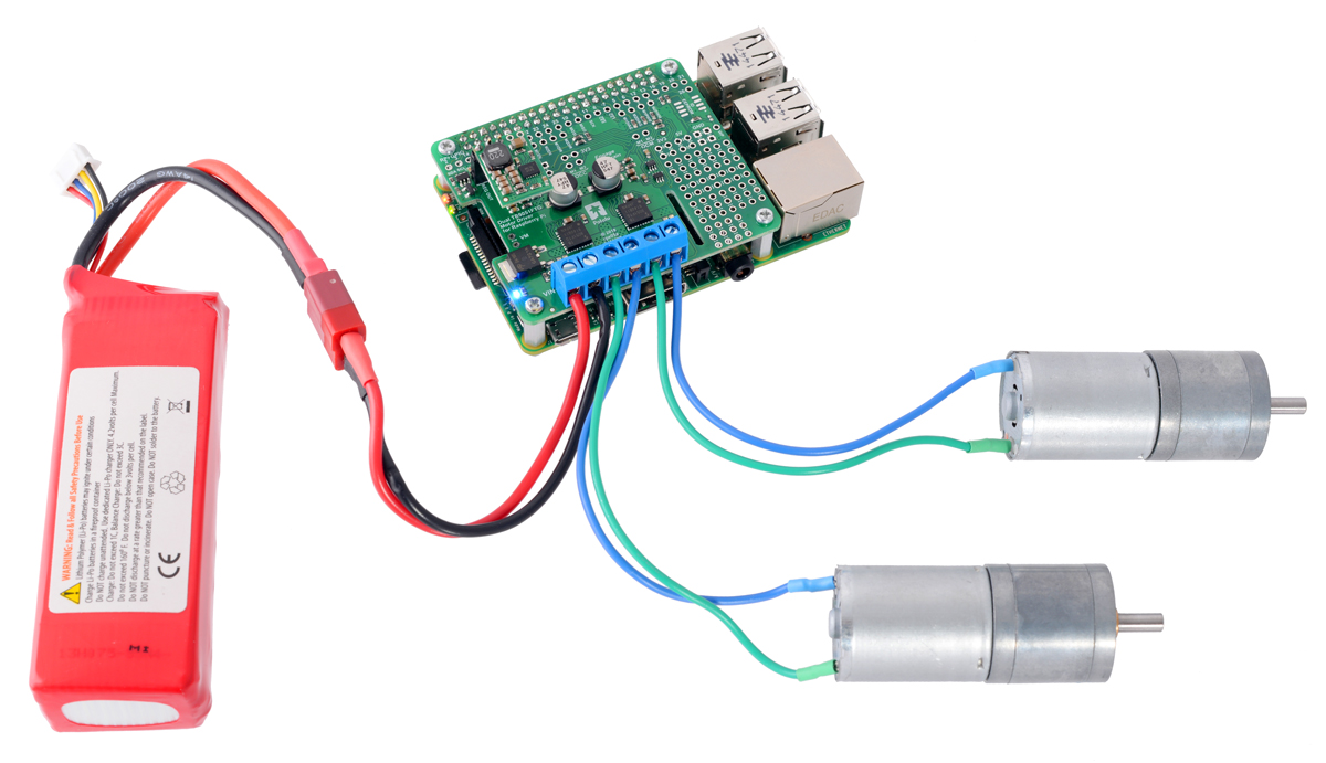 |
Dual TB9051FTG Motor Driver for Raspberry Pi controlling a pair of motors. |
|---|
Default pin mappings
This table shows how the Raspberry Pi’s GPIO pins are used to interface with the motor drivers:
| RPi GPIO pin |
Motor driver pin | Description |
|---|---|---|
| 5 | Motor 1 DIAG | Diagnostic error output: When the driver is functioning normally, this pin should be pulled high by the Raspberry Pi. In the event of a driver fault, the driver IC drives DIAG low. If either of the disable pins (EN or ENB) is disabling the outputs, DIAG will also be low. |
| 6 | Motor 2 DIAG | |
| 12 | Motor 1 PWM | Motor speed input: A PWM (pulse-width modulation) signal on this pin corresponds to a PWM output on the corresponding driver’s motor outputs. When this pin is low, the motor brakes low. When it is high, the motor is on. The maximum allowed PWM frequency is 20 kHz. |
| 13 | Motor 2 PWM | |
| 22 | Motor 1 EN | Enable input: The Raspberry Pi pulls this pin low by default, disabling the motor outputs by setting them to high impedance. EN must be driven high to enable the motor driver. |
| 23 | Motor 2 EN | |
| 24 | Motor 1 DIR | Motor direction input: When DIR is low, motor current flows from output A to output B; when DIR is high, current flows from B to A. |
| 25 | Motor 2 DIR |
Simplified motor control truth table
This table shows how the drivers’ control inputs affect the motor outputs:
| Inputs | Outputs | ||||
|---|---|---|---|---|---|
| EN | DIR | PWM | MxA | MxB | operating mode |
| 1 | 0 | PWM | PWM (H/L) | L | forward/brake at speed PWM % |
| 1 | 1 | PWM | L | PWM (H/L) | reverse/brake at speed PWM % |
| 1 | X | 0 | L | L | brake low (outputs shorted to ground) |
| 0 | X | X | Z | Z | coast (outputs off) |
Remapping pins
All of the Raspberry Pi’s GPIO pins are broken out along a row of numbered through-holes just below the 40-pin GPIO connector. Each GPIO pin used by the board is connected from this row to the corresponding motor driver pin by a trace on the topside of the board spanning the pair of holes. If you want to remap one of these motor driver pins, you can cut its trace with a knife and then run a wire from the lower hole to a new GPIO pin.
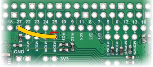 |
Dual TB9051FTG Motor Driver for Raspberry Pi remapping example: moving M2DIR from GPIO pin 25 to pin 27. |
|---|
Note that the default pin mappings were chosen so that the Raspberry Pi’s default GPIO pull-ups and pull-downs match the direction the motor driver pins are or should be pulled (up for DIAG, down for others); if you remap the motor driver pins without paying attention to this, you might encounter issues with pins being pulled the wrong way. See the Raspberry Pi documentation for more about the default GPIO states.
Using additional TB9051FTG pins
The rest of the TB9051FTG inputs and outputs are not connected to the Raspberry Pi, but they are accessible through their own through-holes in case you want to use them in a more advanced application of the motor drivers. The board ties some of the inputs high or low through cuttable traces, similar to the way the remappable pins are connected, and you should cut the trace before connecting each input to anything else. This table shows the default configuration of the additional pins:
| Motor driver pin | Description | Default configuration on board |
|---|---|---|
| ENB | Inverted enable input | Tied low (enabled) through cuttable trace |
| OCC | Over-current response configuration input | Internally pulled low (driver remains disabled after over-current condition) |
| OCM | Current monitor output | Connected to sense resistor and low-pass filter to output approx. 500 mV/A (only active while H-bridge is driving) through an on-board RC filter |
For more information about these pins and how they can be used, refer to the TB9051FTG datasheet (2MB pdf).
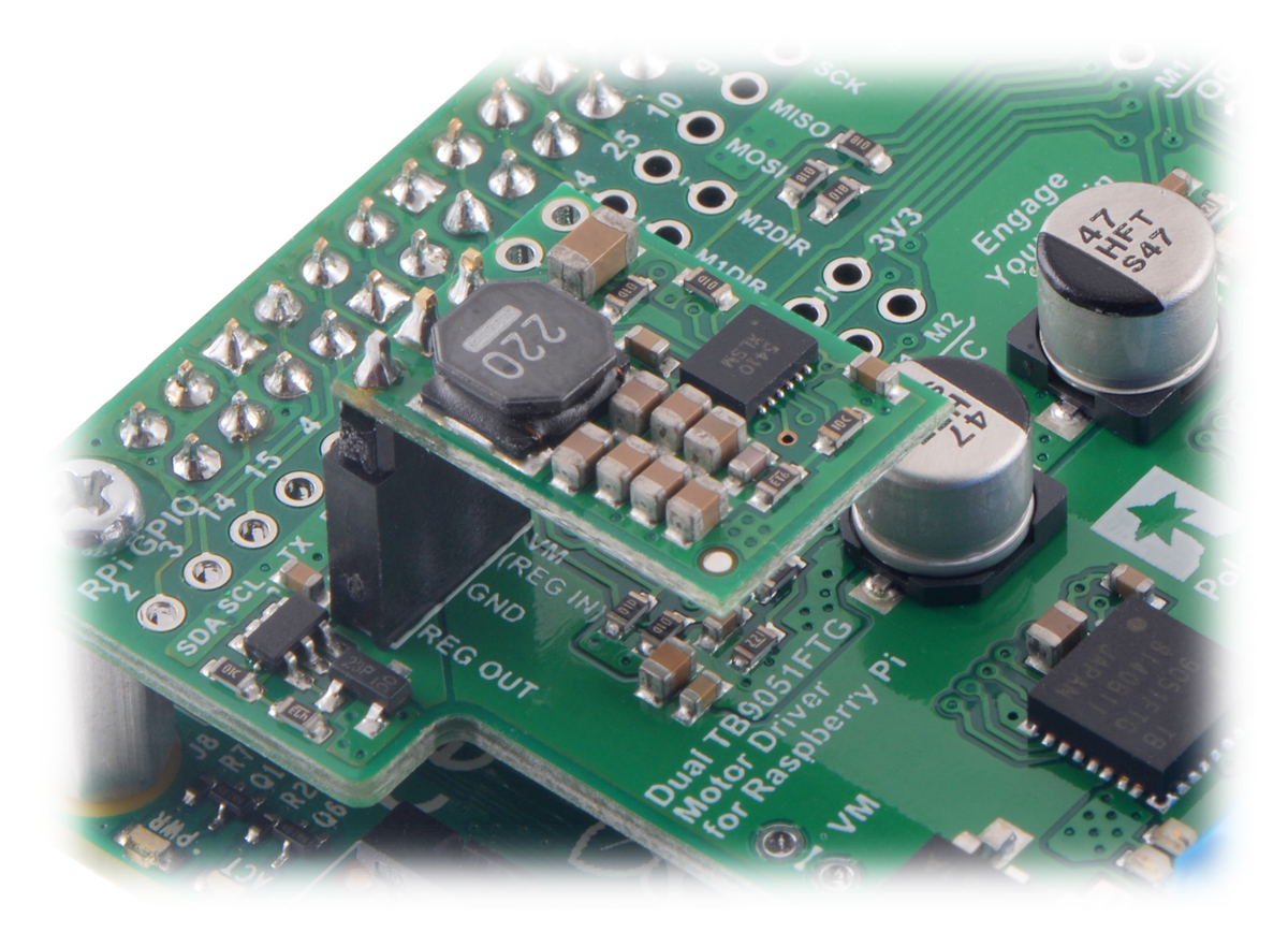
Powering the Raspberry Pi from the motor driver board
On the left side of the expansion board is a set of three pins surrounded by a box labeled “5V Regulator”. The “VM (REG IN)” pin provides access to the driver board’s motor supply voltage after reverse-voltage protection, while the “REG OUT” pin is connected to the Raspberry Pi’s 5V power rail through an ideal diode circuit. If a suitable voltage regulator is connected to these three pins, it can generate 5 V to power the Raspberry Pi from the board’s motor supply voltage.
We suggest using our D24V10F5 or D24V22F5, which work at input voltages exceeding the 28 V maximum of the TB9051FTG (see below for details on which to choose), and can supply up to 500 mA or 1 A of current, respectively, to the Raspberry Pi.
When adding a voltage regulator to the motor driver board, take care to orient it correctly: note that the motor driver board’s “VM (REG IN)” pin should connect to the regulator’s VIN pin, while the regulator’s VOUT pin should connect to the motor driver board’s REG OUT pin.
There are a few considerations to keep in mind when “back-powering” the Raspberry Pi through a voltage regulator in this way:
- Your motor power supply must be an acceptable voltage for both the regulator and the TB9051FTG driver ICs.
- The regulator should be able to handle the power requirements of the Raspberry Pi. The Model B+ typically uses a few hundred milliamps at 5 V, although its current draw can exceed 1 A if it is also supplying power to USB devices and other peripherals. While a linear regulator like a 7805 might fit in the regulator mounting location, it could generate excessive heat or shut down at higher input voltages and output currents. We recommend using a switching regulator like the ones mentioned above.
The ideal diode circuit on this board prevents reverse current from flowing into the motor driver board’s 5 V supply if the Raspberry Pi is separately powered (for example, through its USB power receptacle). However, starting with the Raspberry Pi 3 Model B+, there is no corresponding ideal diode circuit on the Raspberry Pi’s USB power input, so it is possible for the driver board to backfeed a USB power adapter through the Raspberry Pi. As a result, we do not recommend connecting external USB power to the Raspberry Pi while it is powered through the motor driver.
Backfeeding is not an issue with older Raspberry Pi versions, which do have a diode circuit on the USB power input. With Raspberry Pi versions prior to the Pi 3 B+, it is safe to have a different power supply connected to the Raspberry Pi through its USB receptacle while the motor driver add-on and regulator are connected and powered.
The D24V10F5 can supply up to 1 A of current to the Raspberry Pi and should work for lower-power models (like the A+) with lighter loads. It can be soldered directly to the motor driver board with a male header to make a compact, permanent connection:
|
|

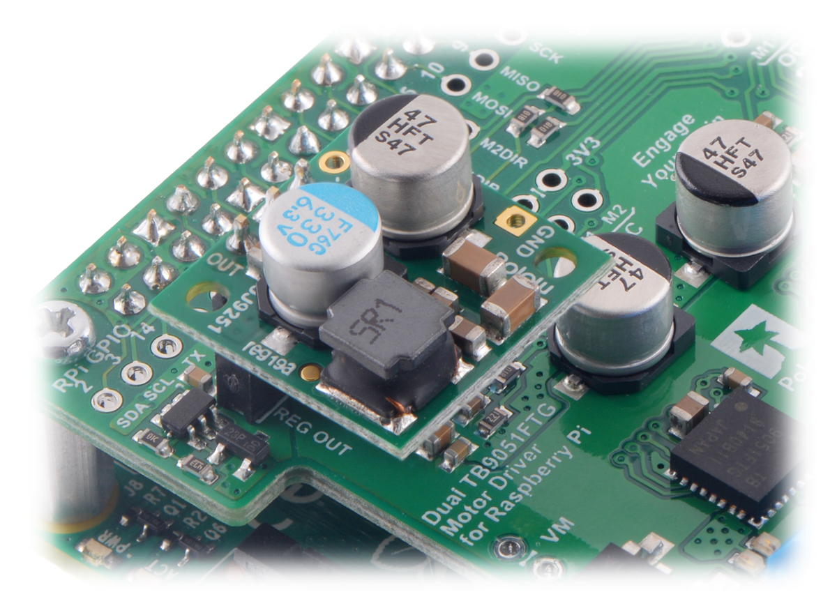
or plugged into a 3-pin female header soldered to the board for a more modular setup:
 |
The D24V22F5 can supply up to 2.5 A and is more suitable for higher-performance Raspberry Pi models (like the Pi 3 B+), especially with demanding workloads or when powering many peripherals.
 |
The FAQs page on the Raspberry Pi website has more information on Raspberry Pi power requirements.
Real-world power dissipation considerations
The TB9051FTG will start chopping its output current at a typical threshold of 6.5 A. However, the chip by itself will typically overheat at lower currents. In our tests, we found that the chip was able to deliver 5 A for only a few seconds before the chip’s thermal protection kicked in; a continuous current of about 2.6 A per channel was sustainable for many minutes without triggering thermal current limiting or an over-temperature shutdown. The actual current you can deliver will depend on how well you can keep the motor driver cool. The driver’s printed circuit board is designed to help with this by drawing heat out of the motor driver chip. PWMing the motor will introduce additional heating proportional to the frequency.
Unlike typical H-bridges, the TB9051FTG has a feature that allows it to gracefully reduce the maximum current limit when the chip temperature approaches its limit. This means that if you push the chip close to its limit, you will see less power to the motor, but it might allow you to avoid a complete shutdown.
This product can get hot enough to burn you long before the chip overheats. Take care when handling this product and other components connected to it.
Schematic diagram
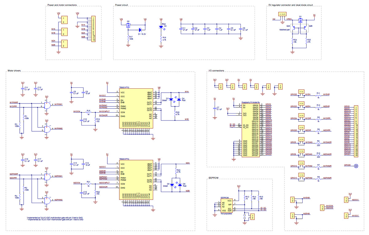 |
This diagram is also available as a downloadable pdf: Dual TB9051FTG Motor Driver for Raspberry Pi schematic (269k pdf).
Related products


Related categories


Home | Forum | Blog | Support | Ordering Information | Lists | Distributors | BIG Order Form | About | Contact
© 2001–2026 Pololu Corporation
