LEDs » Addressable RGB LEDs Based on the SK6812/WS281x » SK6812/WS2812B-Based LED Strips »
Addressable RGB 150-LED Strip, 5V, 5m (SK6812)

This 5-meter long strip contains 150 RGB LEDs that can be individually addressed using a one-wire interface, allowing you full control over the color of each RGB LED. The flexible, waterproof strip runs on 5 V and can be chained with additional SK6812 or WS2812B strips to form longer runs or cut apart between each LED for shorter sections.
Alternatives available with variations in these parameter(s): length RGB LED density Select variant…

| Description | Specs (7) | Pictures (11) | Resources (7) | FAQs (1) | On the blog (2) | Distributors (0) |
|---|
 |
Close up of one segment of a SK6812-based LED strip with the red, green, and blue LEDs on at their dimmest setting. |
|---|
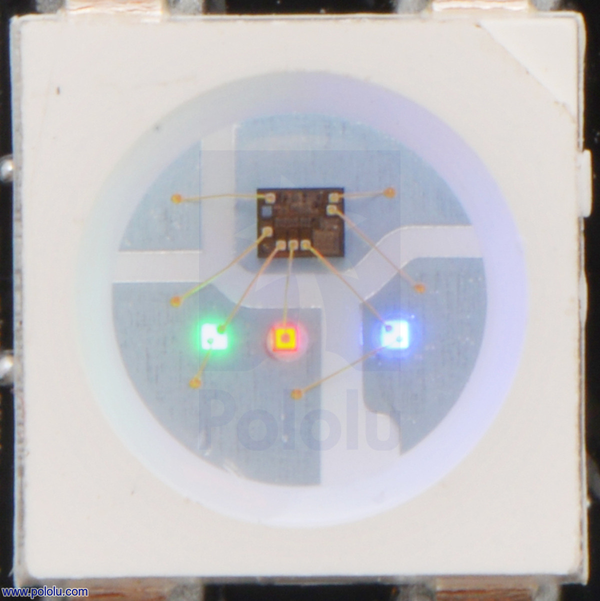 |
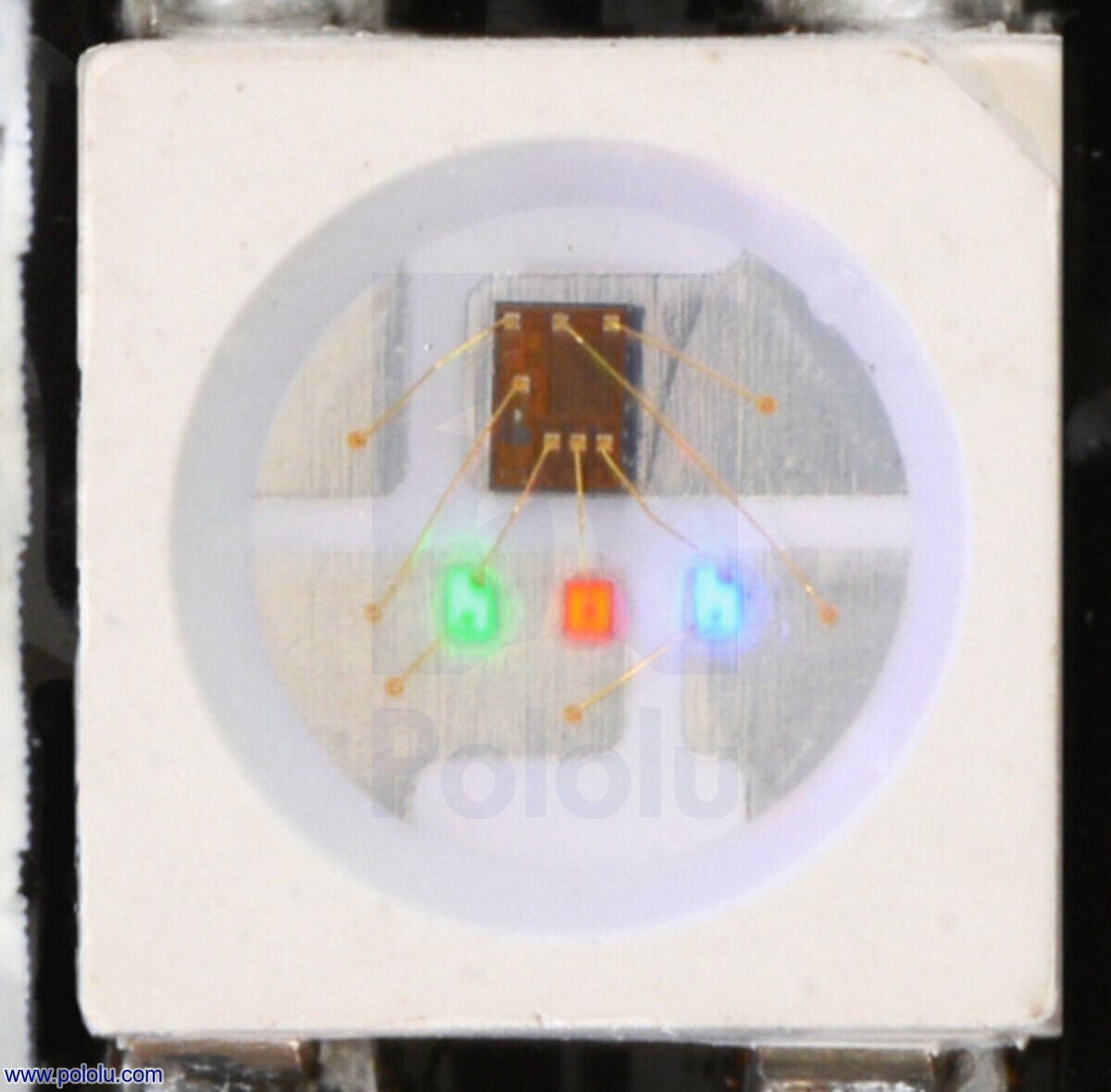
Close up of an SK6812, with the red, green, and blue LEDs on at their dimmest setting. |
|---|
Overview
These flexible RGB LED strips based on the SK6812 LED/driver IC are an easy way to add complex lighting effects to a project. Each LED has an integrated driver that allows you to control the color and brightness of each LED independently. The SK6812’s color and brightness are largely independent of its supply voltage from 3.5 V to 5 V, meaning that voltage drops caused by the resistance in long power connections are less likely to have a visible effect.
These SK6812-based LED strips work as a drop-in replacement for our older WS2812B-based strips in most applications, and they can be chained with the WS2812B-based LED strips. See below for a more detailed comparison of the SK6812 and WS2812B.
In contrast to our APA102C-based LED strips, which use a two-wire SPI interface, the SK6812 is controlled by a one-wire interface with strict timing requirements. See below for a more detailed comparison of the SK6812 and APA102C.
We offer six different kinds of SK6812 LED strip with different LED densities and lengths. Our strips with 30 LEDs per meter are available in three lengths:
We also offer denser SK6812 LED strips that have 60 LEDs per meter:
Our highest density strip has 144 LEDs per meter:
The information on this page applies to all of the SK6812-based LED strips we sell.
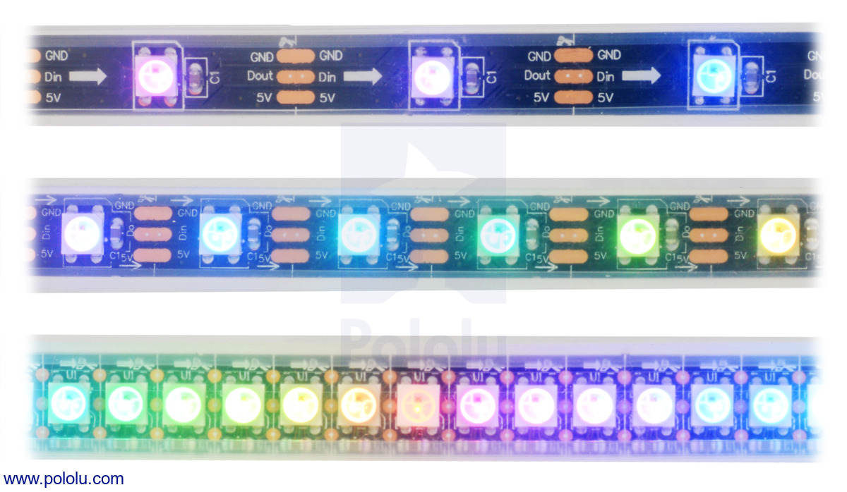 |
LED side of the SK6812-based addressable LED strips, showing 30 LEDs/m (top), 60 LEDs/m (middle), and 144 LEDs/m (bottom). |
|---|
Features and specifications
- Individually addressable RGB LEDs (30, 60, or 144 LEDs per meter)
- 24-bit color control (8 bits per channel)
- One-wire digital control interface
- 5 V typical operating voltage
- Color and brightness are voltage-independent down to 3.5 V
- Each RGB LED draws approximately 40 mA with red, green, and blue at full brightness
- 12 mm width (14 mm for the high-density 144 LEDs per meter strip), 4.6 mm thickness
- Flexible, waterproof silicone rubber sheath (IP65 protection rating)
- Includes flexible silicone mounting brackets
- Black strip color
- Power/data connectors on both strip ends for easy chaining
- Additional power and ground wires on input side for alternate power connections
- Strips can be cut apart along the lines between each RGB LED segment to separate them into usable shorter sections
- Example code available for Arduino, AVR, and mbed
Using the LED strip
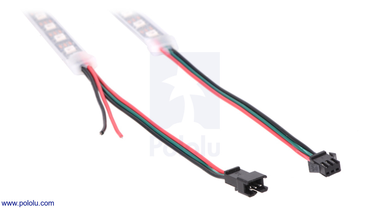 |
The connectors and power wires for addressable LED strips. On the left is the input end of the strip and on the right is the output end. |
|---|
Each LED strip has three connection points: the input connector, the auxiliary power wires, and the output connector. These can be seen in the adjacent picture, from left to right: auxiliary power wires, input connector, output connector. The strip uses 3-pin JST SM connectors.
The input connector has three male pins inside of a plastic connector shroud, each separated by about 0.1″. The black wire is ground, the green wire is the signal input, and the red wire is the power line.
The auxiliary power wires are connected to the input side of the LED strip and consist of stripped black and red wires. The black wire is ground, and the red wire is the power line. This provides an alternate (and possibly more convenient) connection point for LED strip power.
The output connector is on the other end of the strip and is designed to mate with the input connector of another LED strip to allow LED strips to be chained. The black wire is ground, the green wire is the signal output, and the red wire is the power line.
All three black ground wires are electrically connected, and all three red power wires are electrically connected.
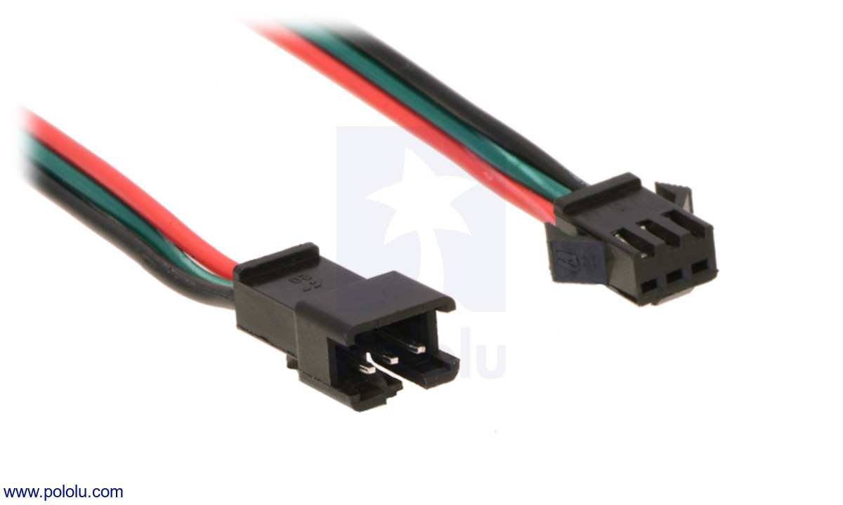 |
A close-up of the JST SM connectors for our addressable LED strips. |
|---|
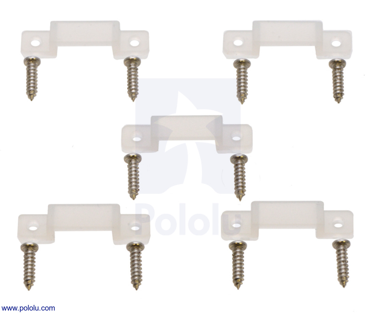
Included hardware
These LED strips ship with flexible silicone brackets and screws. Strips with lengths of 1 meter or greater include five brackets and ten screws per meter. Our 0.5 meter high-density strip ships with a total of two brackets and four screws. The brackets fit over the waterproof sheath and can be used to mount the LED strip. The LED strip also ships on a plastic reel.
|
|

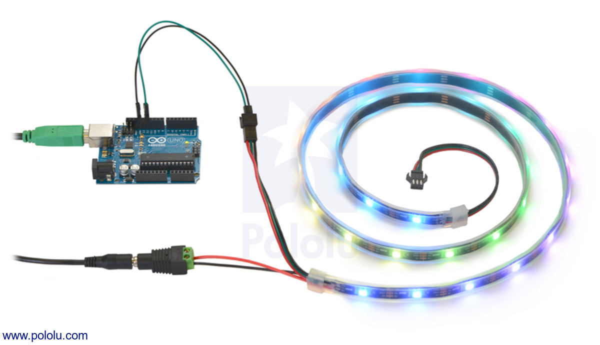 |
Controlling an addressable RGB LED strip with an Arduino and powering it from a 5V wall power adapter. |
|---|
Connecting the LED strip
To control the LED strip from a microcontroller, two wires from the input connector should be connected to your microcontroller. The LED strip’s ground (black) should be connected to ground on the microcontroller, and the LED strip’s signal input line (green) should be connected to one of the microcontroller’s I/O lines. The male pins inside the input connector fit the female terminations on our premium jumper wires and wires with pre-crimped terminals. If you are connecting the LED strip to a breadboard or a typical Arduino with female headers, you would want to use male-female wires.
We generally recommend powering the LED strip using the auxiliary power wires. Our 5 V wall power adapters work well for powering these LED strips and a DC Barrel Jack to 2-Pin Terminal Block Adapter can help you make the connection between the adapter and the strip. However, you might need a wire stripper to strip off some more insulation from the power wires.
It is convenient that the power wires are duplicated on the input side because you can connect the auxiliary power wires to your 5 V power supply and then the power will be available on the data input connector and can be used to power the microcontroller that is controlling the LED strip. This means you can power the microcontroller and LED strip from a single supply without having to make branching power connections.
Making a custom cable
If you do not want to use our premium jumper wires to connect to the LED strip’s input, it is possible to make a custom cable.
One option for making a custom cable is to cut off the unused output connector on the last LED strip in your chain. This can then be plugged into the input connector of the first LED strip. The wires on the output and input connectors are 20 AWG, which is too thick to easily use with our crimp pins and housings, but you could solder the wires to header pins.
Alternatively, you can get your own JST SM connectors and make a custom cable using those. The parts you would need to get are the SMP-03V-BC and the SHF-001T-0.8BS, which are described in the SM Connector datasheet from JST. These can be purchased from several places such as Heilind. You will also need some 22–28 AWG stranded wire and a wire stripper. We do not know of a great way to crimp wires onto the JST crimp pins, but we were able to successfully do it using our narrower crimping tool and pliers. (With the wider crimping tool, it is hard to avoid crimping parts of the pin that should not be crimped.) Before crimping, use pliers to bend the outer set of tabs a little bit so that they can hold on to the insulation of the wire. This makes it easier to position the crimp pin and the wire. Next, you should be able to follow the instructions on the crimping tool product page to crimp the wire. After that, you will probably need to squeeze the crimp pin with pliers to get it to fit into the JST plug housing. On the other end of the cable you could make a custom connector using our crimp pins and crimp connector housings, which will allow you to plug it directly into a breadboard or 0.1″ header pins.
Current draw and voltage independence
Each RGB LED draws approximately 40 mA when it is set to full brightness. This means that for every 30 LEDs you turn on, your LED strip could be drawing as much as 1.2 A. Be sure to select a power source that can handle your strip’s current requirements.
The SK6812 has built-in constant current control. For any given color command, the SK6812’s actual color and brightness are largely independent of its supply voltage as long as the voltage is between 3.5 V and 5 V. This means that voltage drops caused by the resistance in long power connections are less likely to affect the color or brightness of the light emitted.
Chaining
Multiple LED strips can be chained together by connecting input connectors to output connectors. When strips are chained this way, they can be controlled and powered as one continuous strip. Please note, however, that as chains get longer, they will require more power. If this becomes an issue, you can chain the data lines while separately powering shorter subsections of the chain.
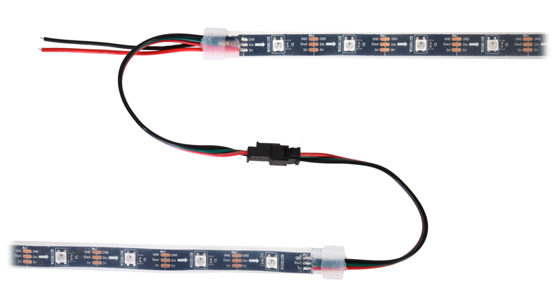 |
Two addressable RGB LED strips connected. |
|---|
We recommend chains of LEDs powered from a single supply not exceed 240 total RGB LEDs. It is fine to make longer chains with connected data lines, but you should power each 240-LED section separately. If you are powering each section from a different power supply, you should cut the power wires between the sections so you do not short the output of two different power supplies together.
Cutting
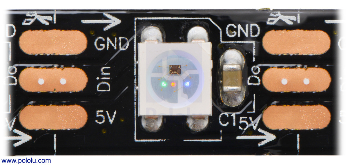
The LED strip is divided into segments, with each segment containing one RGB LED. The strip can be cut apart on the lines between each segment to separate it into usable shorter sections. The data input is labeled Din, the data output is labeled Dout or Do, the positive power connection is labeled 5V, and the ground connection is labeled GND. There are little scissors drawn on the PCB silkscreen where the segments can be cut.
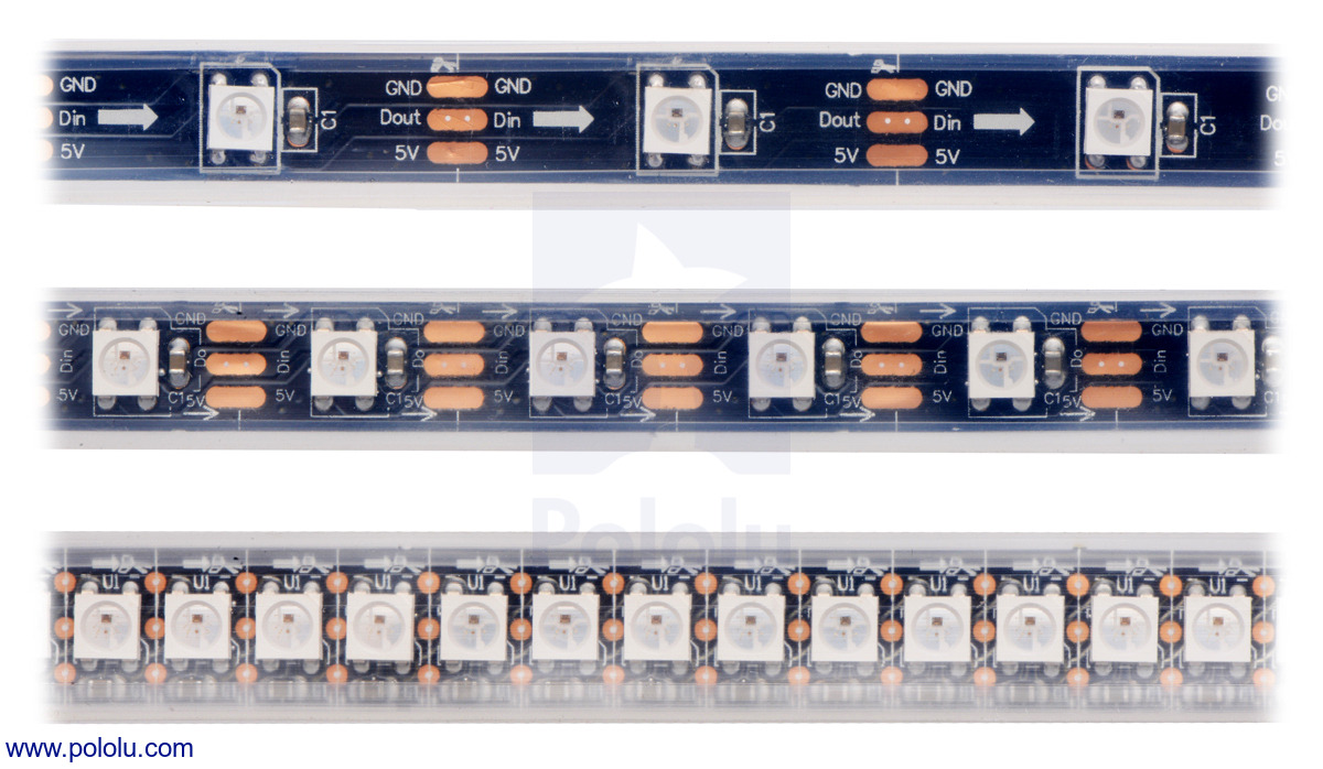 |
LED side of the SK6812-based addressable LED strips, showing 30 LEDs/m (top), 60 LEDs/m (middle), and 144 LEDs/m (bottom). |
|---|
Protocol
These LED strips are controlled by a simple, high-speed one-wire protocol on the input signal line. The protocol is documented in the SK6812 datasheet (459k pdf) and also below.
The default, idle state of the signal line is low. To update the LED colors, you need to transmit a series of high pulses on the signal line. Each high pulse encodes one bit: a short pulse (0.35 μs) represents a zero, while a long pulse (0.9 μs) represents a one. The time between consecutive rising edges should be 1.25 μs (though in our tests, the strips worked with cycle times up to approximately 39 μs). After the bits are sent, the signal line should be held low for 80 μs to send a reset command, which makes the new color data take effect (note: it is possible for low pulses as short as 40 μs to trigger a reset). The pulse widths do not have to be precise: there is a threshold that determines whether the pulse is a 0 or a 1, and a wide range of pulse widths on both sides of the threshold will work.
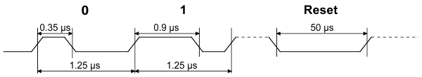 |
SK6812/WS281x RGB data timing diagram. |
|---|
The color of each LED is encoded as three LED brightness values, which must be sent in GRB (green-red-blue) order. Each brightness value is encoded as a series of 8 bits, with the most significant bit being transmitted first, so each LED color takes 24 bits. The first color transmitted applies to the LED that is closest to the data input connector, while the second color transmitted applies to the next LED in the strip, and so on.
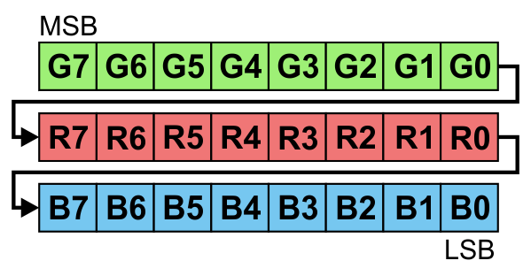 |
24 bits represent the color of one SK6812/WS281x LED in an addressable RGB LED strip. |
|---|
To update all the LEDs in the strip, you should send all the colors at once with no pauses. If you send fewer colors than the number of LEDs on the strip, then some LEDs near the end of the strip will not be updated. For example, to update all 30 LEDs on a 1-meter strip, you would send 720 bits encoded as high pulses and then hold the signal line low for 80 μs. If multiple strips are chained together with their data connectors, they can be treated as one longer strip and updated the same way (two chained 1-meter strips behave the same as one 2-meter strip).
Each RGB LED receives data on its data input line and passes data on to the next LED using its data output line. The high-speed protocol of the SK6812 allows for fast updates; our library for the Arduino below takes about 1.1 ms to update 30 LEDs, so it is possible to update 450 LEDs faster than 60 Hz. However, constant updates are not necessary; the LED strip can hold its state indefinitely as long as power remains connected.
Implementing the protocol on a microcontroller
Since this LED strip does not use a standard protocol, a software bit-banging approach is usually needed to control it from a microcontroller. Because of the sub-microsecond timing, the bit-banging code generally needs to be written in assembly or very carefully optimized C, and interrupts will need to be disabled while sending data to the LED strip. If the interrupts in your code are fast enough, they can be enabled during periods where the signal line is low. The interrupts should be fast enough so that the signal line is never low for longer than 39 μs between bits.
Note: The minimum logic high threshold for the strip data line is 3.4 V, so you should use level-shifters if you want to control these strips from 3.3 V systems. In our tests, we were able to control them with 3.3 V signals from an mbed, but using the strip out of spec like this could lead to unexpected problems.
Sample code
To help you get started quickly, we provide sample code for these microcontroller platforms:
- PololuLedStrip Arduino library (also works with our Arduino-compatible A-star modules)
- Example AVR C code
- PololuLedStrip mbed library
Additionally, the Adafruit NeoPixel library for Arduino should work with these strips.
Since the SK6812 is so similar to the WS2812B, almost any code written for the WS2812B should work with the SK6812.
Comparison with APA102C LED Strips
Like the SK6812, the APA102C used in some of our LED strips also combines an RGB LED and driver into a single 5050-size package. The APA102C uses a standard SPI interface with separate data and clock signals. With its loose timing requirements, the APA102C’s interface is easier to implement on new systems, especially systems that are running a full operating system like Windows or Linux. However, it requires two I/O lines instead of just one.
The APA102C provides a 5-bit color-independent brightness control that is not available on the SK6812. This feature can be used to vary the intensity of each pixel without changing its color, and it enables much subtler variations at the low end of the LEDs’ brightness range.
In addition, the APA102C uses a much higher PWM (pulse-width modulation) frequency for controlling each color channel—about 20 kHz, compared to around 1.2 kHz on the SK6812. As a result, APA102C LEDs can be less prone to flickering when recorded with a camera and are more suited to applications like persistence-of-vision (POV) displays. (The color-independent brightness is modulated separately at about 600 Hz).
The SK6812 has voltage-independent color and brightness over a wide voltage range, as described in the “Current draw and voltage independence” section. This makes it a good choice for installations with power wires longer than a few meters.
Another advantage of the SK6812 is that all the LEDs in a chain are updated at nearly the same time. The LEDs update the color they are displaying when they see a long enough low period on the data line. The transmission delay from one LED to the next is at most 0.5 μs, so if you were controlling a display of 450 LEDs, they would all be updated within a fraction of a millisecond. The APA102Cs update the displayed color as soon as their next color is received. Using our Arduino library, it would typically take over 10 ms to send colors to a chain of 450 APA102Cs, which means that some LEDs would get updated 10 ms before other LEDs in the same chain. This makes the SK6812 a good choice for installations with a large number of LEDs where update latency is a concern.
For more information about the ICs, see the SK6812 datasheet (459k pdf) and APA102C datasheet (1MB pdf).
While our SK6812 strips and APA102C strips are physically very similar, they are not functionally compatible with each other. The easiest way to tell them apart is to look at the strips’ end connectors and the connections between each LED segment: SK6812 strips have three connections (power, data, and ground), while APA102C strips have four (power, clock, data, and ground).
Comparison with WS2812B LED strips
The SK6812 is very similar to the WS2812B used in some of our older LED strips, and can be used as a drop-in replacement in most applications. LED strips based on the SK6812 and WS2812B can be chained together.
The SK6812 datasheet says that the signal line should be low for at least 80 μs to trigger a reset of the strip, whereas the WS2812B datasheet only called for 50 μs. However, in our tests, 40 μs was enough to reset the SK6812, so this difference is unlikely to cause problems. The longer reset time of the SK6812 can be an advantage because the device controlling the LED strip has more time to perform other tasks while updating the LED strip, as described in the “Implementing the protocol on a microcontroller” section above.
The SK6812 has voltage-independent color and brightness over a wide voltage range, as described in the “Current draw and voltage independence” section, which means that the colors of the LEDs should not be affected by a drop in the supply voltage as much as they are on the WS2812B.
The SK6812 can be distinguished from the WS2812B by visual inspection. The pictures below show what each IC looks like.
|
|
Related products


Home | Forum | Blog | Support | Ordering Information | Lists | Distributors | BIG Order Form | About | Contact
© 2001–2026 Pololu Corporation
