Support »
Pololu A-Star 32U4 User’s Guide

View document on multiple pages.
You can also view this document as a printable PDF.
- 1. Overview
- 2. Contacting Pololu
- 3. A-Star 32U4 Micro
- 4. A-Star 32U4 Mini
- 5. A-Star 32U4 Prime
- 6. Getting started
- 7. A-Star 32U4 Arduino library
- 8. The A-Star 32U4 USB interface
- 9. The A-Star 32U4 Bootloader
- 10. Reviving an unresponsive A-Star
- 11. Related Resources
1. Overview
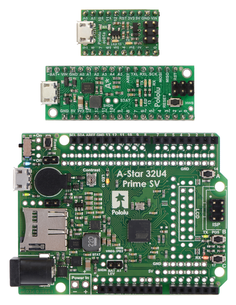 |
From top to bottom: A-Star 32U4 Micro, Mini SV, and Prime SV. |
|---|
The Pololu A-Star 32U4 microcontroller boards are general-purpose programmable modules based on Atmel’s ATmega32U4 AVR microcontroller, which has 32 KB of flash program memory, 2.5 KB of RAM, and built-in USB functionality. Each A-Star (abbreviated A*) adds onboard components and connectors that support the microcontroller and make it easier to use. The boards feature USB interfaces and ship with a preloaded Arduino-compatible bootloader, and we provide a software add-on that enables them to be easily programmed from the Arduino environment. The following sections of this user’s guide discuss each A-Star in more detail.
A USB A to Micro-B cable (not included) is required to connect an A-Star 32U4 to a computer.
Features
- Programmable 16 MHz Atmel ATmega32U4 AVR microcontroller
- 32 KB flash (4 KB used by bootloader, leaving 28 KB available for user program by default)
- 2.5 KB SRAM
- 1 KB EEPROM
- Native full-speed USB (12 Mbps)
- Preloaded with Arduino-compatible bootloader
- Can be powered from USB or external source regulated to 5 V by onboard regulator
- Reverse-voltage protection on external power input
- 6-pin ISP header for use with an external programmer
A-Star comparison table
 |
 |
   |
  |
  | |
|---|---|---|---|---|---|
| A-Star 328PB Micro | A-Star 32U4 Micro | A-Star 32U4 Mini ULV A-Star 32U4 Mini LV A-Star 32U4 Mini SV |
A-Star 32U4 Prime LV A-Star 32U4 Prime SV |
A-Star 32U4 Robot Controller LV A-Star 32U4 Robot Controller SV |
|
| Microcontroller: | ATmega328PB | ATmega32U4 | |||
| User I/O lines: | 24 | 18 | 26 | 26(1) | 26(1) |
| Available PWM outputs: | 9 | 6 | 7 | 7 | 7(1) |
| Analog inputs: | 8 | 8 | 12 | 12 | 12(1) |
| Ground access points: | 6 | 2 | 4 | 43 | 44 |
| User LEDs: | 1 | 2 | 3 | 3 | 3 |
| User pushbuttons: | — | — | — | 3 | 3 |
| USB interface: |  |
|
|
|
|
| Reset button: | |
|
|
|
|
| Power switch: | |
|
|||
| Buzzer option: | |
|
|||
| microSD option: | |
||||
| LCD option: | |
||||
| Motor drivers: | |
||||
| Operating voltage: | 3.3V VCC: 3.8 V to 15 V 5V VCC: 5.5 V to 15 V |
5.5 V to 15 V | ULV: 0.5 V to 5.5 V LV: 2.7 V to 11.8 V SV: 5 V to 40 V |
LV: 2 V to 16 V SV: 5 V to 36 V |
LV: 2.7 V to 11 V SV: 5.5 V to 36 V |
| Regulator type: | 3.3 V or 5 V linear | 5 V linear | 5 V switching ULV: step-up LV: step-up/step-down SV: step-down |
5 V switching LV: step-up/step-down SV: step-down |
5 V switching LV: step-up/step-down SV: step-down |
| Regulated current:(2) | 100 mA | 100 mA | ULV: 500 mA LV: 1 A SV: 800 mA |
LV: 1.8 A SV: 1 A |
LV: 1 A SV: 1.5 A |
| Dimensions: | 1.3″ × 0.7″ | 1″ × 0.6″ | 1.9″ × 0.7″ | 2.8″ × 2.1″ | 2.6″ × 2.2″ |
| Weight: | 1.5 g(3) | 1.3 g(3) | 3.4 g(3) | 13 g to 33 g | 14 g to 23 g |
| Price: | $11.72 | $19.95 | $29.95 to $29.95 | $33.40 to $53.00 | $39.05 to $54.84 |
| 1 Some microcontroller resources are used by on-board hardware. | |||||
| 2 These values are rough approximations for comparison purposes. Available current depends on input voltage, current consumed by the board, ambient conditions, and regulator topology. See product documentation and performance graphs for details. | |||||
| 3 Without included optional headers. | |||||
1.1. Supported operating systems
The A-Star 32U4 boards can be programmed using Microsoft Windows 11, 10, 8.1, 8, 7, Vista, XP (with Service Pack 3), Linux, and macOS 10.11 or later.
2. Contacting Pololu
 |
We would be delighted to hear from you about any of your projects and about your experience with the Pololu A-Stars. You can contact us directly or post on our forum. Tell us what we did well, what we could improve, what you would like to see in the future, or anything else you would like to say!
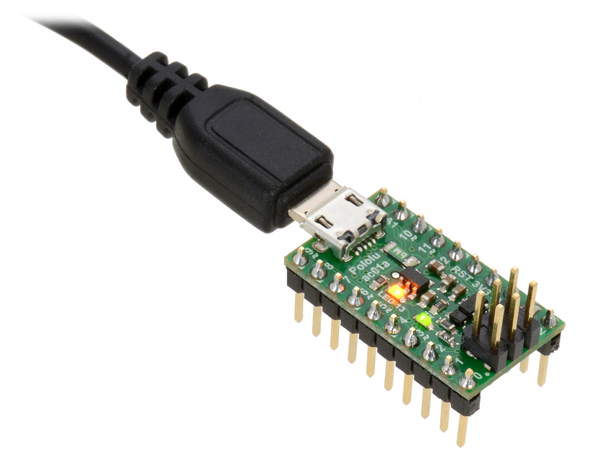
3. A-Star 32U4 Micro
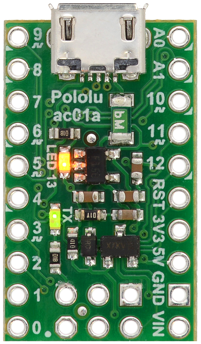 |
A-Star 32U4 Micro, top view. |
|---|
3.1. A-Star 32U4 Micro pinout and components
Pinout
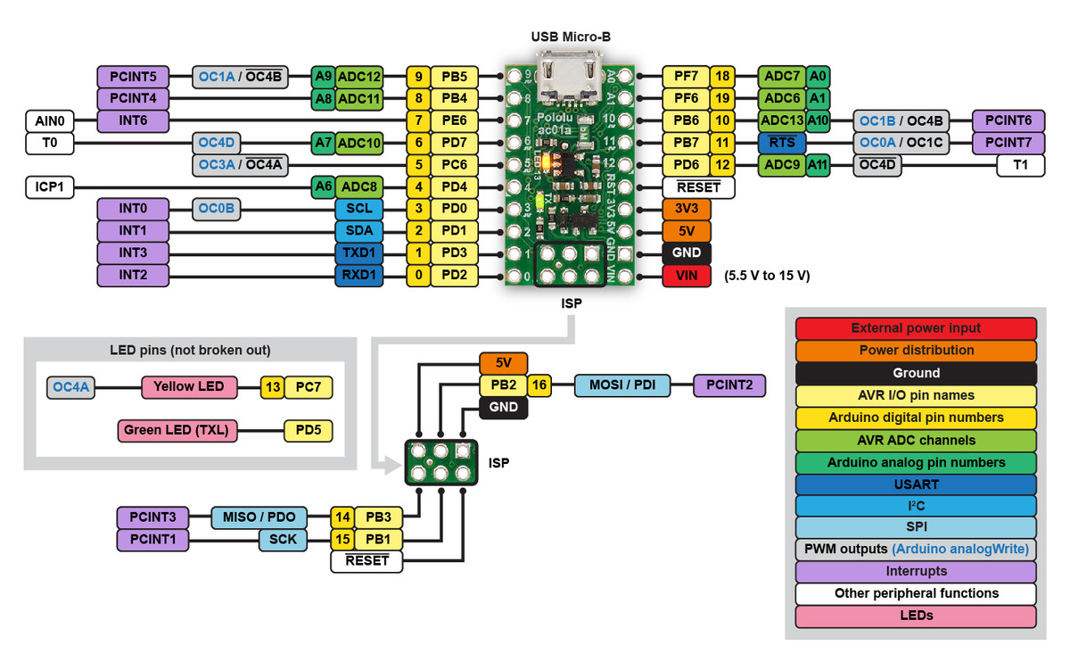 |
The diagram above identifies the I/O and power pins on the A-Star 32U4 Micro; it is also available as a printable PDF (409k pdf). For more information about the ATmega32U4 microcontroller on this board, see Atmel’s ATmega32U4 documentation.
Printed on the A* circuit board are indicators that you can use to quickly identify each pin’s capabilities: a triangle next to the pin means it can be used as an analog input, and a square wave symbol under the pin number means it can be used as a PWM output.
LEDs
The A-Star 32U4 Micro has two indicator LEDs.
The yellow LED is connected to Arduino pin 13, or PC7. You can drive this pin high in a user program to turn this LED on. The A-Star 32U4 Bootloader fades this LED on and off while it is waiting for a sketch to be loaded.
The green LED is connected to PD5 and lights when the pin is driven low. While the board is running the A-Star 32U4 Bootloader or a program compiled in the Arduino environment, it will flash this LED when it is transmitting data via the USB connection.
Connectors
The A-Star 32U4 includes a USB Micro-B connector that can be used to connect to a computer’s USB port via a USB A to Micro-B cable (not included). The USB connection can be used to transmit and receive data from the computer, and a preloaded USB bootloader makes it possible to program the board over USB. The USB connection can also provide power to the A-Star.
The board also has a 6-pin ISP header that allows it to be programmed with an external programmer, such as our USB AVR programmer v2.1. Pin 1 of the header is indicated with a small white dot and has an octagonal shape. Three of the pins on this header can be used as an SPI interface or as general-purpose digital I/O, as shown in the pinout diagram. In the Arduino environment, you can refer to these three pins using either their pin numbers or the names of their SPI functions (which are defined as aliases); for example, digitalRead(15) and digitalRead(SCK) are equivalent.
Power
The A-Star 32U4 Micro can either be powered directly from the USB 5 V supply or from a separate source on the VIN pin. The board features a power selection circuit that allows both USB and VIN to be connected at the same time; if this is done, the A-Star will draw power from VIN.
USB power input: The A-Star can be powered from the USB 5 V bus voltage (VBUS) if it is connected to a USB cable. It will draw power from USB only if VIN is disconnected. A resettable PTC fuse on VBUS makes it less likely for the A-Star (and the connected computer or other device) to be damaged if too much current is drawn from the USB connection.
VIN power input: The A-Star can be powered from VIN if you connect a 5.5 V to 15 V power supply (such as a battery or wall power adapter) to the VIN and GND pins, with the positive terminal connected to VIN.
When powering the A-Star 32U4 Micro from VIN, a minimum voltage of 5.5 V is required to ensure that the board’s 5 V supply is stable. Even if power is being provided to the A-Star via USB, connecting a voltage higher than 0 V but lower than 5.5 V to VIN is not recommended, as this can interfere with the power selection circuit and cause the 5 V line to drop (potentially triggering a brown-out reset).
5V power output: This pin provides access to the board’s 5 V supply, which comes from either the USB 5 V bus voltage or a low-dropout (LDO) regulator on VIN, depending on which power source is connected. The regulator can supply up to 100 mA, although some of this is used by the board itself (typically about 25 mA) or used to provide current for the GPIO pins or 3.3 V power output (see below).
3V3 power output: This pin gives access to the output of the internal 3.3 V regulator inside the ATmega32U4. The microcontroller uses this regulated voltage for USB signaling, but up to about 50 mA is available for powering external circuits or devices.
When the A-Star 32U4 Micro is being powered through VIN, the sum of the 5V output current, 3V3 output current, GPIO output current, and current used by the board itself should not exceed the 100 mA that the regulator can provide.
3.2. A-Star 32U4 Micro schematic and dimensions
Schematic diagram
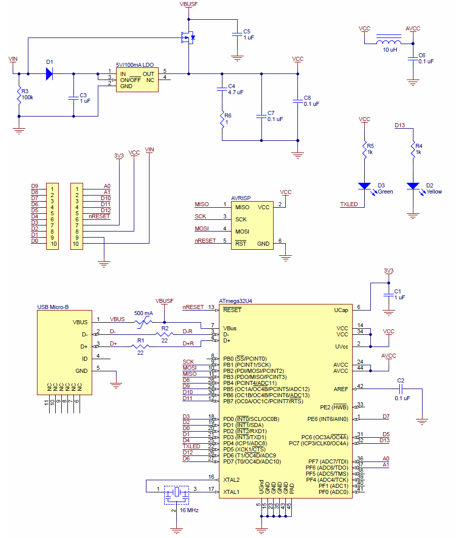 |
Pololu A-Star 32U4 Micro schematic diagram. |
|---|
This schematic is also available as a PDF: A-Star 32U4 Micro schematic diagram (253k pdf).
Dimension diagram
A dimension diagram of the A-Star 32U4 Micro is available as a PDF: A-Star 32U4 Micro dimension diagram (255k pdf).
4. A-Star 32U4 Mini
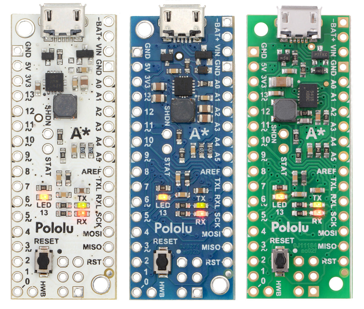 |
A-Star 32U4 Mini ULV, LV, and SV. |
|---|
4.1. A-Star 32U4 Mini pinout and components
Pinout
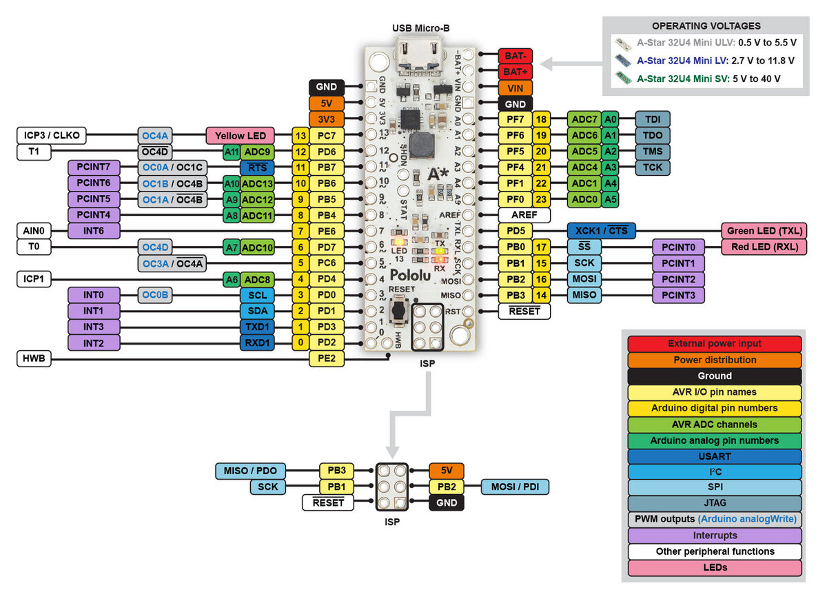 |
This diagram identifies the I/O and power pins on the A-Star 32U4 Mini (ULV, LV, and SV versions); it is also available as a printable PDF (223k pdf). For more information about the ATmega32U4 microcontroller and its peripherals, see Atmel’s ATmega32U4 documentation.
Printed on the A* circuit board are indicators that you can use to quickly identify each pin’s capabilities: a triangle next to the pin means it can be used as an analog input, and a square wave symbol under the pin number means it can be used as a PWM output.
LEDs
The A-Star 32U4 Mini has three indicator LEDs.
The yellow LED is connected to Arduino pin 13, or PC7. You can drive this pin high in a user program to turn this LED on. The A-Star 32U4 Bootloader fades this LED on and off while it is waiting for a sketch to be loaded.
The green LED is connected to the pin labeled TXL, or PD5, and lights when the pin is driven low. While the board is running the A-Star 32U4 Bootloader or a program compiled in the Arduino environment, it will flash this LED when it is transmitting data via the USB connection.
The red LED is connected to the pin labeled RXL (usable as Arduino pin 17), or PB0, and lights when the pin is driven low. While the board is running the A-Star 32U4 Bootloader or a program compiled in the Arduino environment, it will flash this LED when it is receiving data via the USB connection.
Connectors
The A-Star 32U4 includes a USB Micro-B connector that can be used to connect to a computer’s USB port via a USB A to Micro-B cable (not included). The USB connection can be used to transmit and receive data from the computer, and a preloaded USB bootloader makes it possible to program the board over USB. The USB connection can also provide power to the A-Star.
The board also has a 6-pin ISP header that allows it to be programmed with an external programmer, such as our USB AVR programmer v2.1. Pin 1 of the header is indicated with a small dot and has an octagonal shape.
Power
The A-Star 32U4 Mini can either be powered directly from the USB 5 V supply or from an external voltage source, which is regulated to 5 V by its onboard switching regulator.
The board’s power selection circuit uses the TPS2113A power multiplexer from Texas Instruments to choose whether its 5 V supply is sourced from USB or an external supply via the regulator, allowing both sources to be connected at the same time and enabling the A-Star to safely and seamlessly transition between them. The TPS2113A is configured to select external power unless the regulator output falls below about 4.5 V. If this happens, it will select the higher of the two sources, which will typically be the USB 5 V bus voltage if the A* is connected to USB. The currently selected source is indicated by the STAT pin in the middle of the board; this pin is an open-drain output that is low if the external power source is selected and high-impedance if the USB supply is selected. The current limit of the TPS2113A is set to about 1.9 A. For more information about the power multiplexer, see the TPS2113A datasheet (1k redirect).
In some situations, it might be undesirable for the A-Star 32U4 Mini to draw power from an external source when it is connected to USB. If this is the case, the regulator can be disabled by driving the regulator shutdown pin, SHDN, high; this shuts down the regulator and causes the power mux to fall back to USB power. For example, this could allow a battery-powered device to turn off the regulator and avoid draining its battery while it is connected to a computer.
The input voltage range of the regulator depends on the particular version of the A-Star 32U4 Mini:
- ULV: 0.5 V to 5.5 V (see Section 4.2 for regulator details)
- LV: 2.7 V to 11.8 V (see Section 4.3 for regulator details)
- SV (see Section 4.4 for regulator details):
- original ac02c version: 5 V to 36 V
- newer ac02f version: 5 V to 40 V
Reverse-protected power inputs: The BAT+ and BAT- pins are power inputs with reverse-voltage protection. These are the recommended pins to use when connecting an external power supply because they allow the A-Star’s reverse-voltage protection circuit to help prevent it from being damaged by accidentally-reversed power connections.
VIN power output (or alternative input): When power is supplied through the BAT pins, the VIN pin can be used as an output to supply reverse-protected power to other devices. Alternatively, the external supply can be connected directly between VIN and GND, bypassing the reverse-voltage protection.
5V power output: This pin provides access to the board’s 5 V supply, which comes from either the USB 5 V bus voltage or the onboard switching regulator, depending on which power sources are connected and enabled. Note that some of the available current on the 5 V line is used by the board itself (typically about 30 mA) or used to provide current for the GPIO pins or 3.3 V power output (see below).
3V3 power output: This pin gives access to the output of the internal 3.3 V regulator inside the ATmega32U4. The microcontroller uses this regulated voltage for USB signaling, but up to about 50 mA is available for powering external circuits or devices.
When the A-Star 32U4 Mini is being powered through VIN, the sum of the 5V output current, 3V3 output current, GPIO output current, and current used by the board itself should not exceed the maximum current that the regulator can provide; see the following sections for details about the regulator on each version.
4.2. A-Star 32U4 Mini ULV regulator
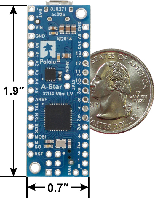
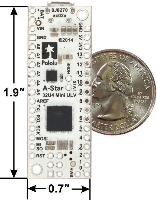 |
A-Star 32U4 Mini ULV, bottom view with dimensions. |
|---|
The A-Star 32U4 Mini ULV can be powered from a 0.5 V to 5.5 V external source. The input voltage is regulated to 5 V by a TPS61202 switching step-up (boost) converter from Texas Instruments. (We also make a standalone regulator based on this integrated circuit.)
The regulator’s low minimum input voltage makes it possible to power this A* with 1 to 3 NiMH, NiCd, or alkaline cells or from a single lithium cell. Unlike standard boost regulators, the TPS61202 also features a linear down-regulation mode that is automatically enabled when the input voltage exceeds 5 V, allowing it to handle input voltages as high as 5.5 V.
As shown in the left graph below, the ULV’s switching regulator has an efficiency – defined as (Power out)/(Power in) – of 70% to 90% for most combinations of input voltage and load.
|
|
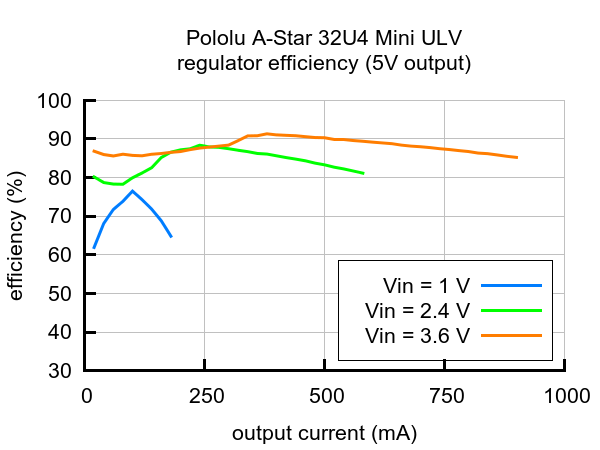
The A-Star’s components, including the microcontroller and LEDs, draw 30 mA to 40 mA in typical applications. The rest of the regulator’s achievable output current, which depends on input voltage as well as ambient conditions, can be used to power other devices. The right graph above shows output currents at which the voltage regulator’s over-temperature protection typically kicks in after a few seconds. These currents represent the limit of the regulator’s capability and cannot be sustained for long periods; a good estimate for the maximum continuous regulator output current is 60% to 70% of the values shown in the graph.
4.3. A-Star 32U4 Mini LV regulator
 |
A-Star 32U4 Mini LV, bottom view with dimensions. |
|---|
The A-Star 32U4 Mini LV can be powered from a 2.7 V to 11.8 V external source. The input voltage is regulated to 5 V by a TPS63061 switching step-up/step-down (buck-boost) converter from Texas Instruments. (We also make a standalone regulator based on this integrated circuit.)
The regulator’s flexibility in input voltage is especially well-suited for battery-powered applications in which the battery voltage begins above 5 V and drops below 5 V as the battery discharges. Without the typical restriction on the battery voltage staying above 5 V throughout its life, a wider range of battery types can be considered. For example:
- A 4-cell battery holder, which might have a 6 V output with fresh alkalines or a 4.0 V output with partially discharged NiMH cells, can be used to power this A*.
- A disposable 9 V battery powering the board can be discharged to under 3 V instead of cutting out at 6 V, as with typical linear or step-down regulators.
As shown in the left graph below, the LV’s switching regulator has an efficiency – defined as (Power out)/(Power in) – of 80% to 90% for most combinations of input voltage and load.
|
|

The A-Star’s components, including the microcontroller and LEDs, draw 30 mA to 40 mA in typical applications. The rest of the regulator’s achievable output current, which depends on input voltage as well as ambient conditions, can be used to power other devices. The right graph above shows output currents at which the voltage regulator’s over-temperature protection typically kicks in after a few seconds. These currents represent the limit of the regulator’s capability and cannot be sustained for long periods; a good estimate for the maximum continuous regulator output current is 60% to 70% of the values shown in the graph.
4.4. A-Star 32U4 Mini SV regulators
There have been two versions of the A-Star 32U4 Mini SV: the original ac02c version and its replacement, the newer ac02f version. The ac02f version uses an improved 5 V regulator that can deliver more current (800 mA vs 500 mA) and operates to 40 V instead of 36 V. The easiest way to distinguish between the two versions is via the silkscreen on the side of the board opposite the USB connector, where the original version is labeled ac02c and the new version is labeled ac02f. The new version also uses an ENIG finish, so the plating on the exposed copper looks gold, and it has unplated mounting holes. See the picture below for a side-by-side comparison:
 |
A-Star 32U4 Mini SV: comparison of original ac02c version (left) to newer ac02f version (right). |
|---|
The A-Star 32U4 Mini SV (ac02c) is the original version of the Mini SV, and it can be powered from a 5 V to 36 V external source. The input voltage is regulated to 5 V by a 500 mA ISL85415 switching step-down (buck) converter from Renesas (which acquired Intersil). (We also make a standalone regulator based on this integrated circuit.)
The A-Star 32U4 Mini SV (ac02f) is the newest version of the Mini SV, and it can be powered from a 5 V to 40 V external source. The input voltage is regulated to 5 V by an 800 mA ISL85418 switching step-down converter, which is part of the same family as the ISL85415. (We also make a standalone regulator based on the 1 A version of this integrated circuit.)
The graphs below show the efficiency of the two SV versions, where efficiency is defined as (Power out)/(Power in):
|
|
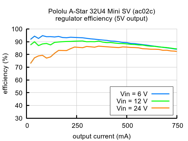

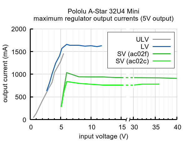
The A-Star’s components, including the microcontroller and LEDs, draw 30 mA to 40 mA in typical applications. The rest of the regulator’s achievable output current, which depends on input voltage as well as ambient conditions, can be used to power other devices. The green lines in the graph below show the output currents where the regulator’s output voltage drops below 4.75 V. These currents are close to the limits of the regulator’s capability and generally cannot be sustained for long periods; under typical operating conditions, a safe limit for the maximum continuous regulator output current is approximately 500 mA for ac02c and 800 mA for ac02f.
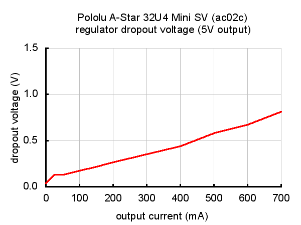
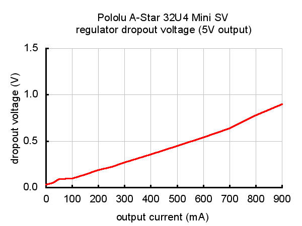
 |
The dropout voltage of a step-down regulator is defined as the minimum amount by which the input voltage much exceed the regulator’s target output voltage in order to assure the target output can be achieved. As can be seen in the graphs below for the two versions of the Mini SV, the dropout voltages of the Mini SV’s regulators increase approximately linearly with the output current. For light loads where the dropout voltage is small, the boards can operate down to 5 V. However, for larger loads, the dropout voltage should be taken into consideration when selecting a power supply; operating above 6 V will ensure the full output current is available.
|
|
Note: Batteries can have much higher voltages than their nominal voltages when fully charged, so be careful with nominal voltages above 24 V. A 36 V battery is not appropriate for this product.
4.5. A-Star 32U4 Mini schematic and dimensions
Schematic diagram
The schematic diagram for the A-Star 32U4 Minis is available as a PDF: A-Star 32U4 Mini schematic diagram (243k pdf).
Dimension diagrams
Dimension diagrams for the A-Star 32U4 Minis are available as PDFs:
- A-Star 32U4 Mini ULV dimension diagram (342k pdf)
- A-Star 32U4 Mini LV dimension diagram (346k pdf)
- A-Star 32U4 Mini SV dimension diagram (208k pdf)
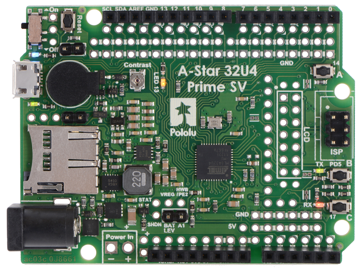
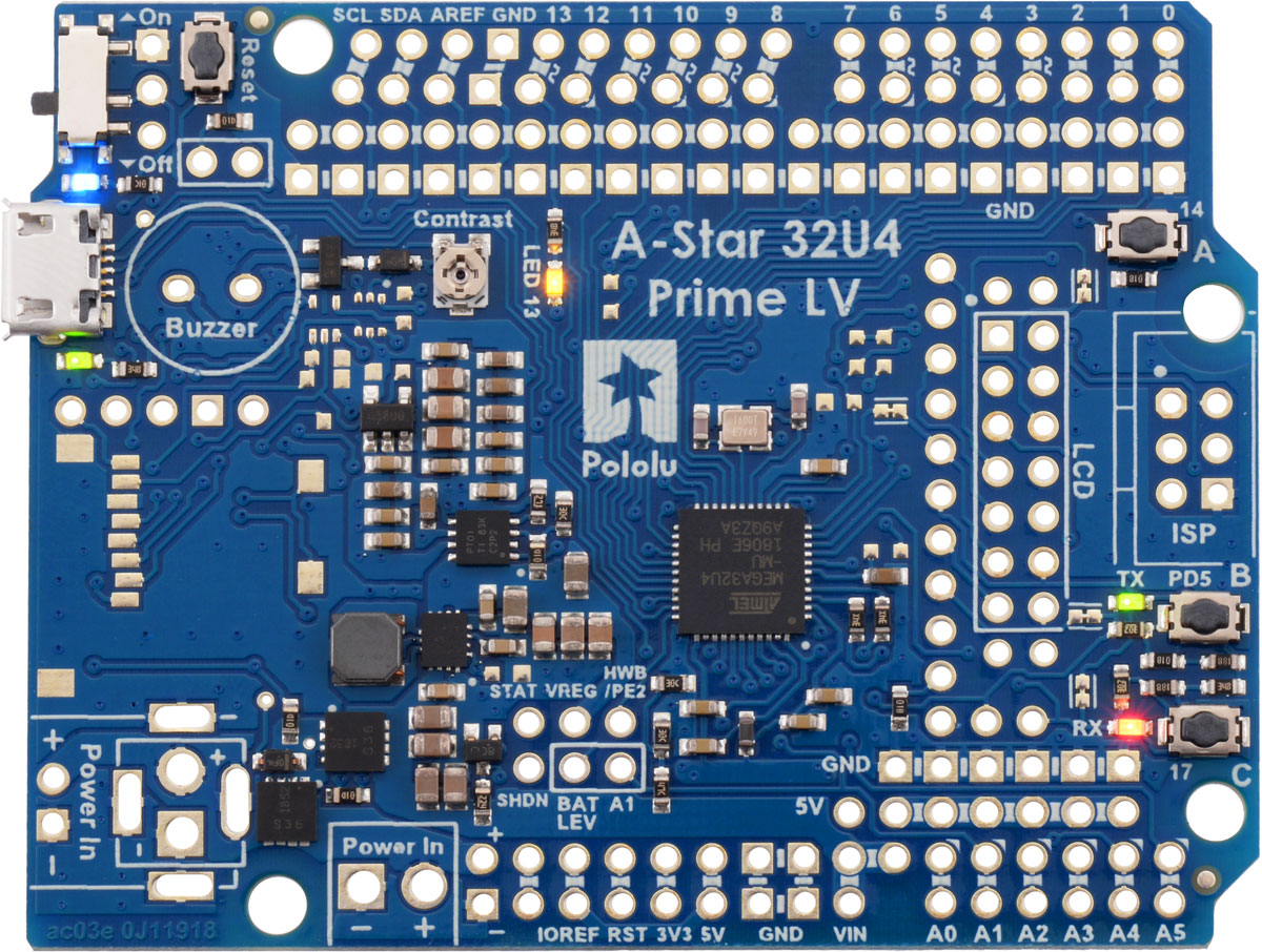
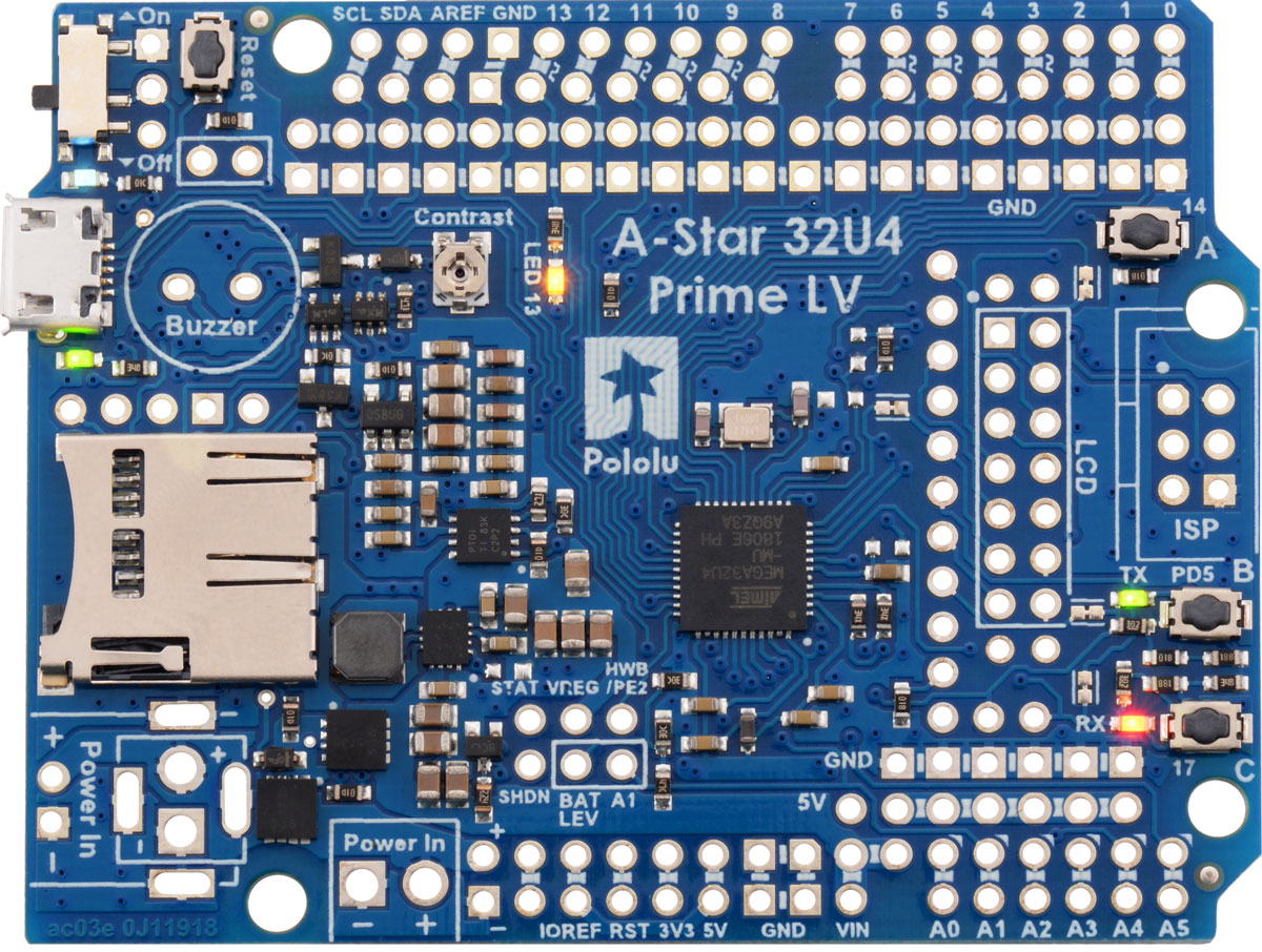
5. A-Star 32U4 Prime
|
|
5.1. A-Star 32U4 Prime configurations
The A-Star 32U4 Prime LV (blue solder mask, 2 V to 16 V operating voltage range) and SV (green solder mask, 5 V to 36 V operating voltage range) are each available in five different versions, allowing you to choose the right amount of customizability and features for your application. (The pictures here show the LV board, but they also reflect the corresponding SV configurations.)
 |
A-Star 32U4 Prime LV (SMT Components Only)
A-Star 32U4 Prime SV (SMT Components Only)
This version comes with all surface-mount components soldered to the board (including the USB connector, pushbuttons, and power switch), except for the microSD card connector and level shifters, which are not populated. It comes with no headers, DC barrel jack, or buzzer.
 |
A-Star 32U4 Prime LV microSD (SMT Components Only)
A-Star 32U4 Prime SV microSD (SMT Components Only)
This version adds the microSD card connector and level shifters, but is otherwise identical to the preceding version.
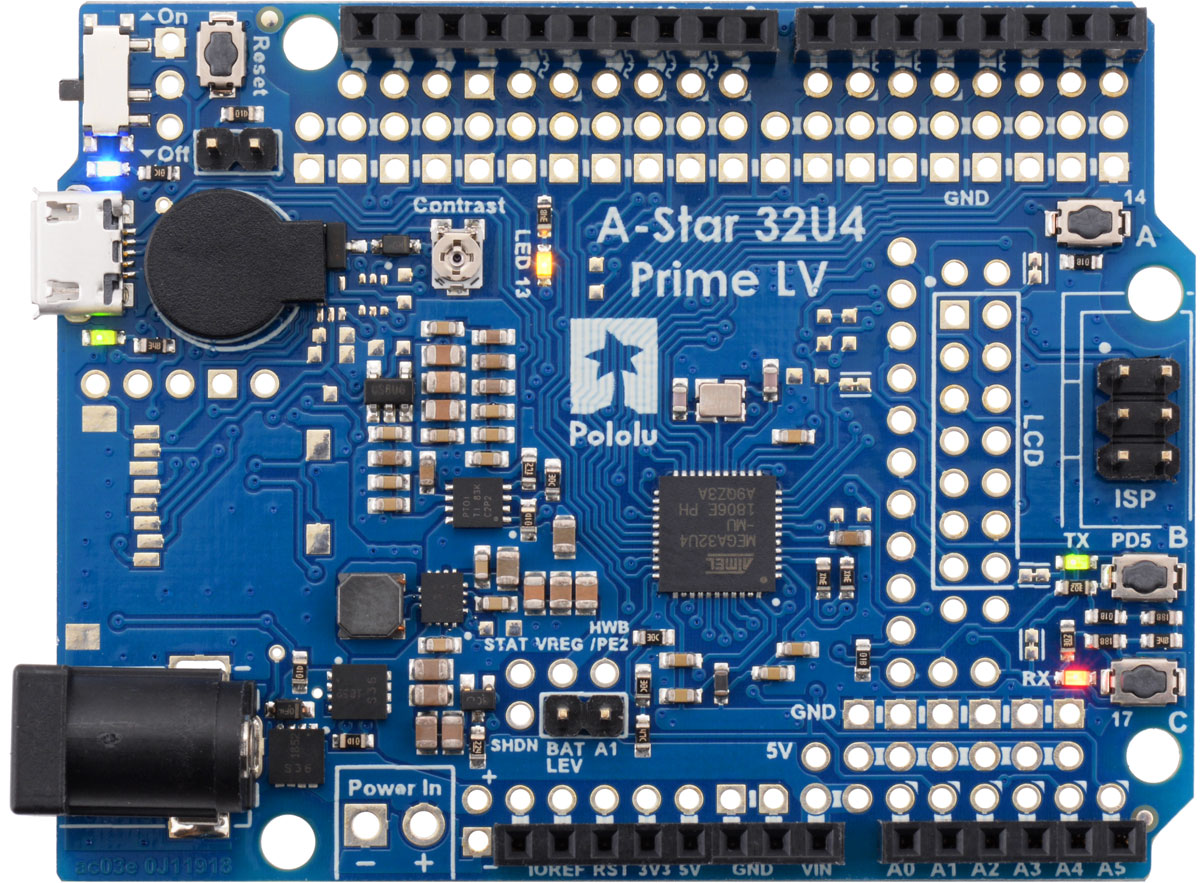 |
A-Star 32U4 Prime LV
A-Star 32U4 Prime SV
This version comes with all surface-mount components except for the microSD card connector and level shifters. These through-hole parts are also soldered in:
- four standard Arduino female headers (one 1×6, two 1×8, one 1×10) on the outermost pins, matching an Arduino Leonardo or Uno R3
- 6-pin ISP header (2×3 male)
- DC barrel jack
- buzzer
- 1×2 low-profile male header for buzzer jumper (shorting block included)
- 1×2 low-profile male header for battery level jumper (shorting block included)
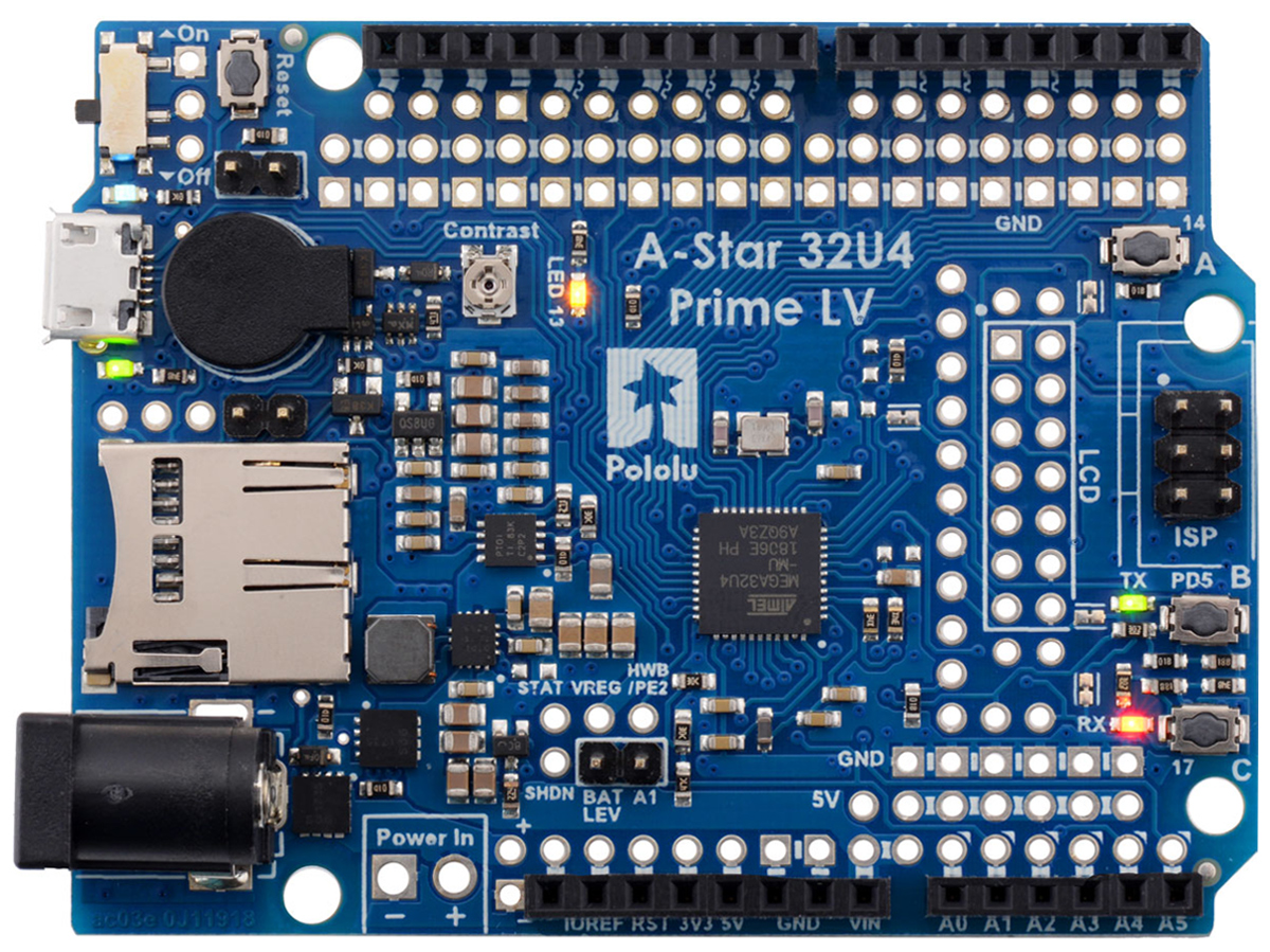 |
A-Star 32U4 Prime LV microSD
A-Star 32U4 Prime SV microSD
This version adds the microSD card connector and level shifters, as well as a third 1×2 low-profile male header and shorting block for the microSD CS jumper, but is otherwise identical to the preceding version.
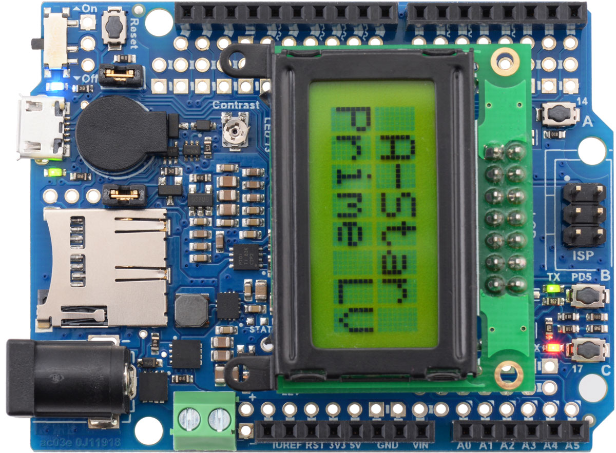 |
A-Star 32U4 Prime LV microSD with LCD
A-Star 32U4 Prime SV microSD with LCD
This version is the same as the preceding version, but it comes with a 8×2 character LCD (with 2×7 female header soldered), and the following parts are additionally soldered to the board:
- LCD connector (2×7 male header)
- 3.5 mm screw terminal block
For users wishing to populate some or all of the through-hole parts on an SMT-only version of the A-Star 32U4 Prime (or to add more functionality to another version), we offer an A-Star Prime accessory pack that contains these items:
- four standard Arduino female headers (one 1×6, two 1×8, one 1×10)
- four 1×25 male header strips
- 2×3 male header (ISP)
- 2×7 male header (LCD)
- 2×7 female header (LCD)
- 1×2 female header
- 1×10 low-profile male header strip
- three low-profile shorting blocks
- buzzer
- DC barrel jack
- 2-pin 3.5 mm screw terminal block
The 8×2 character LCD is also available separately.
Note: The A-Star 32U4 Prime does not come with a microSD card. The microSD connector is an optional feature that can be used to increase the data storage available to the board, but it is not required.
5.2. A-Star 32U4 Prime pinout and components
Pinout
 |
This diagram identifies the I/O and power pins on the A-Star 32U4 Prime (LV and SV versions); it is also available (along with the power distribution diagram below) as a printable PDF (1MB pdf). For more information about the ATmega32U4 microcontroller and its peripherals, see Atmel’s ATmega32U4 documentation.
The outermost rows of pins of the A-Star 32U4 Prime correspond to the pins on an Arduino Leonardo, and each is duplicated on a second inner row for more convenient access. Printed on the A* circuit board are indicators that you can use to quickly identify each I/O pin’s capabilities: a triangle by the inner through hole means the pin can be used as an analog input, and a square wave symbol next to the hole pair means the pin can be used as a PWM output.
Additional rows of power and ground pins also run along most of the I/O pins to allow easy connections to devices like sensors and servos. The innermost pin is ground, and the second-innermost is power, which is not connected by default. The power pins are split into three buses: one bus for pins A0–A4 along the bottom, and two buses along the top, split between digital pins 7 and 8. You can configure each bus separately by using a jumper to connect it to a voltage source of your choice. (Access points for 5V and VIN are adjacent to the A0–A4 bus, so it can be conveniently connected to either supply with a shorting block.)
 |
Compatibility with Arduino shields and accessories
The A-Star 32U4 Prime matches the Arduino Leonardo and the Arduino Uno R3 in the shape of its circuit board and the arrangement of its pins. Furthermore, it uses the same ATmega32U4 microcontroller as the Leonardo, running at the same voltage and frequency, so the A* should generally work with any shield or accessory that is compatible with the Leonardo (including our Zumo Robot for Arduino).
LEDs
The A-Star 32U4 Prime has five indicator LEDs.
A blue power LED located next to the power switch indicates when the onboard regulator is active (an external power supply is connected and the switch is turned on).
A green power LED next to the USB connector indicates when the USB bus voltage (VBUS) is present.
A yellow user LED is connected to Arduino pin 13, or PC7. You can drive this pin high in a user program to turn this LED on. The A-Star 32U4 Bootloader fades this LED on and off while it is waiting for a sketch to be loaded.
A green user LED is connected to PD5 and lights when the pin is driven low. While the board is running the A-Star 32U4 Bootloader or a program compiled in the Arduino environment, it will flash this LED when it is transmitting data via the USB connection.
A red user LED is connected to Arduino pin 17, or PB0, and lights when the pin is driven low. While the board is running the A-Star 32U4 Bootloader or a program compiled in the Arduino environment, it will flash this LED when it is receiving data via the USB connection.
The AStar32U4Prime library contains functions that make it easier to control the three user LEDs. All three user LED control lines are also LCD data lines, so you will see them flicker when you update the LCD. The green and red user LEDs also share I/O lines with pushbuttons (see below).
Pushbuttons
The A-Star 32U4 Prime has four pushbuttons: a reset button next to the power switch and three user pushbuttons located along the right edge of the board. The user pushbuttons, labeled A, B, and C, are on Arduino pin 14 (PB3), PD5, and Arduino pin 17 (PB0), respectively. Pressing one of these buttons pulls the associated I/O pin to ground through a resistor.
The three buttons’ I/O lines are also used for other purposes: pin 14 is MISO on the SPI interface, PD5 and pin 17 control the green and red user LEDs, and all three pins are LCD data lines. Although these uses require the pins to be driven by the AVR (or SPI slave devices in the case of MISO), resistors in the button circuits ensure that the A-Star will not be damaged even if the corresponding buttons are pressed at the same time, nor will SPI or LCD communications be disrupted. The functions in the AStar32U4Prime library take care of configuring the pins, reading and debouncing the buttons, and restoring the pins to their original states.
Note that button A cannot be used if the microSD CS pin is tied to ground with a jumper (see microSD card connector and level shifters below).
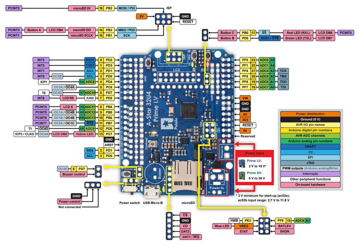
 |
Buzzer and CS-GND jumpers on the A-Star 32U4 Prime. |
|---|
Buzzer
The assembled versions of the A-Star 32U4 Prime come with a buzzer that can be used to generate simple sounds and music. The buzzer is not present on the SMT-only versions, but the buzzer driver circuit is still populated, allowing you to solder in your own buzzer or speaker. The stock buzzer is available as part of the A-Star 32U4 Prime accessory pack.
A through-hole jumper next to the buzzer provides a way to connect the buzzer input to digital pin 6 (which also serves as OC4D, a hardware PWM output from the AVR’s 10-bit Timer4). If you alternate between driving the buzzer pin high and low at a given frequency, the buzzer will produce sound at that frequency. You can play notes and music with the buzzer using functions in the AStar32U4PrimeBuzzer library.
microSD card connector and level shifters
Some versions of the A-Star 32U4 Prime include an onboard microSD card connector that enables the microcontroller to read from and write to microSD memory cards. The card socket is connected to the SPI interface on the ATmega32U4 through level-shifting circuits, allowing the 5 V microcontroller to safely communicate with standard 3.3 V SD cards. DI, DO, and SCLK on the card are connected to MOSI, MISO, and SCK on the AVR, respectively. The Arduino SD library can be used to access the file system on an inserted microSD card.
A fourth pin, CS (chip select), must be held low to enable communication with the microSD card in SPI mode. This can be done by connecting one of the microcontroller’s I/O lines to CS (the SD library examples use digital pin 4 by default) and driving the pin low to select the microSD card. The CS line also controls whether the output of the DO level shifter is enabled: when CS is high, the level shifter places its output into a high-impedance state, allowing the MISO line to be driven by other SPI slave devices, used as an LCD control line, or read as a pushbutton input.
Alternatively, you can tie CS low more easily by shorting it to the adjacent ground pin, causing the microSD card to always be selected and the DO level shifter output to always be enabled. This allows you to avoid using an extra I/O line and making an additional connection, but the DO level shifter output will override the pushbutton on the same pin and prevent any presses on button A from being detected. You should remove the CS-GND jumper when no microSD card is present, as asserting CS with no microSD card inserted can put the DO level shifter output into an undefined state.
The CD (card detect) pin next to the connector can be used to detect the presence of a microSD card: it is floating when a card is inserted and shorted to ground when a card is not present. Two additional SD data lines (DAT1 and DAT2), which are unused in SPI mode, are also broken out for advanced uses.
LCD
The A-Star 32U4 Prime has a mounting location for a 2×7 header where you can connect a character LCD with the common HD44780 parallel interface (109k pdf). The A* is optionally available with a male header installed here and an 8×2 character LCD (with corresponding female header) included; on other versions, you can add your own display using the connectors of your choice. A larger LCD can be connected with a ribbon cable and optionally a shrouded box header.
The LCD control lines are broken out to a column of through holes next to the LCD connector, labeled on the back side of the board. By default, some of these are connected to I/O lines from the ATmega32U4 to allow control of the LCD in 4-bit mode, but you can remap the connections by cutting the surface-mount jumpers indicated in the picture below and making new connections between I/O lines and LCD control pins.
 |
The AStar32U4PrimeLCD library provides functions to display data on a connected LCD. It is designed to gracefully handle alternate use of the LCD data lines by only changing pin states when needed for an LCD command, after which it will restore them to their previous states. This allows the LCD data lines to be used for other functions (such as pushbutton inputs and LED drivers).
Other connectors
The A-Star 32U4 includes a USB Micro-B connector that can be used to connect to a computer’s USB port via a USB A to Micro-B cable (not included). The USB connection can be used to transmit and receive data from the computer, and a preloaded USB bootloader makes it possible to program the board over USB. The USB connection can also provide power to the A-Star.
The board also has a 6-pin ISP header that allows it to be programmed with an external programmer, such as our USB AVR programmer v2.1. Pin 1 of the header is indicated with a small dot and has an octagonal shape. Three of the pins on this header can be used as an SPI interface or as general-purpose digital I/O, as labeled on the back side of the board and shown in the pinout diagram. In the Arduino environment, you can refer to these three pins using either their pin numbers or the names of their SPI functions (which are defined as aliases); for example, digitalRead(15) and digitalRead(SCK) are equivalent. If you have an SMT-only version of the A-Star, it is possible to solder a shrouded box header to this location; the outlines on the board indicate the correct connector orientation.
Power
The A-Star 32U4 Prime can either be powered directly from the USB 5 V supply or from an external voltage source, which is regulated to 5 V by its onboard switching regulator. The slide switch on A* controls whether the external source is connected to the input of the regulator, providing a convenient way to switch off external power to the A-Star without unplugging any connections. The adjacent set of three pins provides a place to connect your own power switch: to enable external power, connect the middle pin to ground (accessible through the upper pin).
When the A-Star is connected to a computer via USB, it will receive 5V power even when the power switch is off. This can be useful if you want to upload or test a program without drawing external power (to avoid draining a battery pack, for example).
The board’s power selection circuit uses the TPS2113A power multiplexer from Texas Instruments to choose whether its 5 V supply is sourced from USB or an external supply via the regulator, allowing both sources to be connected at the same time and enabling the A-Star to safely and seamlessly transition between them. The TPS2113A is configured to select external power unless the regulator output falls below about 4.5 V. If this happens, it will select the higher of the two sources, which will typically be the USB 5 V bus voltage if the A* is connected to USB. The currently selected source is indicated by the STAT pin in the middle of the board; this pin is an open-drain output that is low if the external power source is selected and high-impedance if the USB supply is selected. The current limit of the TPS2113A is set to about 1.9 A. For more information about the power multiplexer, see the TPS2113A datasheet (1k redirect).
In some situations, it might be undesirable for the A-Star 32U4 Prime to draw power from an external source when it is connected to USB, even if the power switch is left on. If this is the case, the regulator can be disabled by driving the regulator shutdown pin, SHDN, high; this shuts down the regulator and causes the power mux to fall back to USB power. For example, this could allow a battery-powered system to automatically turn off the regulator while it is connected to a computer.
The input voltage range of the regulator depends on the particular version of the A-Star 32U4 Prime:
- LV (ac03b): 2.7 V to 11.8 V (see Section 5.3 for regulator details)
- LV (ac03e): 2 V to 16 V (see Section 5.3 for regulator details)
- SV: 5 V to 36 V (see Section 5.4 for regulator details)
Reverse-protected and switched power inputs: The connection points labeled “Power In” are power inputs with reverse-voltage protection that are controlled by the power switch. These are the recommended pins to use when connecting an external power supply because they allow the A-Star’s reverse-voltage protection circuit to help prevent it from being damaged by accidentally-reversed power connections, and they enable the A-Star’s power switch to disconnect the supply.
A number of different connectors can be soldered to the board and used to provide power, including a DC barrel jack or a 3.5 mm screw terminal block (the assembled versions of the board come with one or both of these populated).
Warning: You must never connect different power sources to multiple Power In locations at the same time, as doing so will create a short between the supplies.
VIN power output (or alternative input): When power is supplied through the Power In pins, the VIN pin can be used as an output to supply reverse-protected and switched power to other devices. Alternatively, the external supply can be connected directly between VIN and GND, bypassing the reverse-voltage protection and power switch.
5V power output: This pin provides access to the board’s 5 V supply, which comes from either the USB 5 V bus voltage or the onboard switching regulator, depending on which power sources are connected and enabled. Note that some of the available current on the 5 V line is used by the board itself (typically at least 30 mA, but potentially much more if peripherals like the buzzer are active) or used to provide current for the GPIO pins or 3.3 V regulator (see below).
3V3 power output: This pin gives access to the output of the onboard 3.3 V linear regulator. The microSD card, if present, draws power from the 3.3 V line; the remainder (up to a few hundred milliamps) is available for powering external circuits or devices.
When the A-Star 32U4 Prime is being powered through Power In, the sum of the 5V output current, 3V3 output current, GPIO output current, and current used by the board itself should not exceed the maximum current that the switching regulator can provide.
In a battery-powered application, it might be useful for the A-Star to monitor the battery’s voltage level. The BATLEV pin provides access to a voltage divider that outputs a fraction of the VIN voltage (one-third on the ac03b LV, one-fourth on the ac03e LV, and one-eighth on the SV), and this voltage can be read by connecting it to the adjacent analog pin 1 (A1) (or another analog input). The readBatteryMillivoltsLV3(), readBatteryMillivoltsLV4(), and readBatteryMillivoltsSV() functions in the AStar32U4 library can be used to determine the battery voltage from this reading.
5.3. A-Star 32U4 Prime LV regulator
There have been two versions of the A-Star 32U4 Prime LV: the original ac03b version and its replacement, the newer ac03e version. The ac03e version uses an improved 5 V regulator that can deliver more current (1.8 A vs 1.5 A) and operates from 2 V to 16 V instead of 2.7 V to 11.8 V. The easiest way to distinguish between the two versions is via the silkscreen on the bottom side of the board, above and to the left of the Pololu logo, where the original version is labeled ac03b and the new version is labeled ac03e. See the picture below for a side-by-side comparison:
 |
A-Star 32U4 Prime LV: comparison of original ac03b version (left) to newer ac03e version (right). |
|---|
The A-Star 32U4 Prime LV (ac03b) is the original version of the Prime LV, and it can be powered from a 2.7 V to 11.8 V external source. The input voltage is regulated to 5 V by a 1.5 A TPS63061 switching step-up step-down (buck-boost) converter from Texas Instruments. (We also make a standalone regulator based on this integrated circuit.)
The A-Star 32U4 Prime LV (ac03e) is the newest version of the Prime LV, and it can be powered from a 2 V to 16 V external source (though it requires at least 3 V at start-up). The input voltage is regulated to 5 V by a 1.8 A TPS630701 switching step-up step-down (buck-boost) converter from Texas Instruments. (We also make a standalone regulator based on this integrated circuit.)
For both versions of the Prime LV, the regulators’ flexibility in input voltage is especially well-suited for battery-powered applications in which the battery voltage begins above 5 V and drops below 5 V as the battery discharges. Without the typical restriction on the battery voltage staying above 5 V throughout its life, a wider range of battery types can be considered. For example:
- A 4-cell battery holder, which might have a 6 V output with fresh alkalines or a 4.0 V output with partially discharged NiMH cells, can be used to power this A*.
- A disposable 9 V battery powering the board can be discharged to under 3 V instead of cutting out at 6 V, as with typical linear or step-down regulators.
The graphs below show the efficiency of the two LV versions, where efficiency is defined as (Power out)/(Power in):
|
|
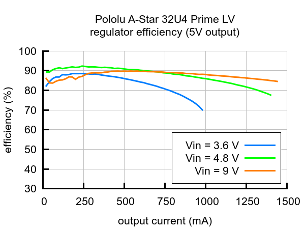

The A-Star’s components, including the microcontroller and LEDs, draw 30 mA to 40 mA in typical applications. The rest of the regulator’s achievable output current, which depends on input voltage as well as ambient conditions, can be used to power other devices. Maximum ouput currents for both versions of the A-Star Prime LVs are shown in the graph below. These currents are close to the limits of the regulators’ capabilities and generally cannot be sustained for long periods; under typical operating conditions, a safe limit for the maximum continuous regulator output current is approximately 1.5 A for ac03b and 1.8 A for ac03e.
 |
Note that the startup current for the regulator on the A-Star 32U4 Prime LV (ac03e) is limited to approximately 700 mA, and currents in excess of this are only available after the output has finished rising to 5 V.
5.4. A-Star 32U4 Prime SV regulator
 |
The A-Star 32U4 Prime SV can be powered from a 5 V to 36 V external source. The input voltage is regulated to 5 V by a 1 A ISL85410/ISL854102 switching step-down (buck) converter from Intersil. (We also make a standalone regulator based on this integrated circuit.)
As shown in the left graph below, the SV’s switching regulator has an efficiency – defined as (Power out)/(Power in) – of 80% to 95% for most combinations of input voltage and load.
|
|
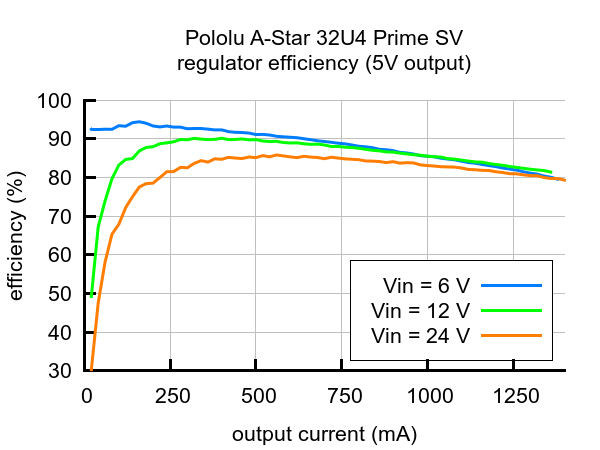

The A-Star’s components, including the microcontroller and LEDs, draw 30 mA to 40 mA in typical applications (without the buzzer, microSD card, or an LCD). The rest of the regulator’s achievable output current, which depends on input voltage as well as ambient conditions, can be used to power other devices. The right graph above shows the output currents where the regulator’s output voltage drops below 4.75 V. These currents are close to the limits of the regulator’s capability and generally cannot be sustained for long periods; under typical operating conditions, a safe limit for the maximum continuous regulator output current is approximately 1 A.
The dropout voltage of a step-down regulator is defined as the minimum amount by which the input voltage much exceed the regulator’s target output voltage in order to assure the target output can be achieved. As can be seen in the graph below, the dropout voltage of the Prime SV’s regulator increases approximately linearly with the output current. For light loads where the dropout voltage is small, the board can operate down to 5 V. However, for larger loads, the dropout voltage should be taken into consideration when selecting a power supply; operating above 6 V will ensure the full output current is available.
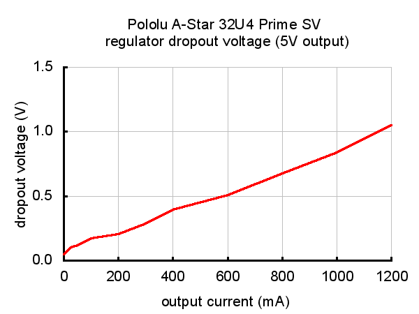 |
Typical dropout voltage of the 5 V regulator on the A-Star 32U4 Prime SV. |
|---|
Note: Although the ISL85410/ISL854102 is rated for a maximum operating input voltage of 36 V, it is not appropriate to power the Prime SV with a 36 V battery, as battery voltages can be much higher than nominal voltages when they are charged. The maximum nominal battery voltage we recommend is 24 V, and if you approach that limit, you should take extra precautions to prevent LC voltage spikes from damaging the board (see this application note for more information). A good practice is to ensure that the A-Star’s power switch is off before connecting it to a voltage source.
5.5. A-Star 32U4 Prime schematic and dimensions
Schematic diagram
The schematic diagrams for the A-Star 32U4 Primes are available as PDFs:
- A-Star 32U4 Prime LV schematic diagram (ac03e) (382k pdf)
- A-Star 32U4 Prime LV schematic diagram (ac03b) (686k pdf)
- A-Star 32U4 Prime SV schematic diagram (564k pdf)
Dimension diagram
The dimension diagrams for the A-Star 32U4 Primes are available as PDFs:
5.6. A-Star 32U4 Prime demo program
The A-Star 32U4 Prime LV microSD with LCD and A-Star 32U4 Prime SV microSD with LCD each come preloaded with a program that demonstrates many of its features and allows you to test that it is working correctly, and this demo program will run when you first turn on the board.
The demo program uses the standard A-Star 32U4 Prime LCD pins, buzzer pin, button pins, microSD pins, and pin 4. To avoid damage or improper operation, if you have shields or other electronics connected, make sure they do not use those pins in a conflicting way.
|
Buzzer and CS-GND jumpers on the A-Star 32U4 Prime. |
|---|
When the demo program starts, you should see the words “A-Star Prime” and then “Demo Program” appear. If you do not see any text on the LCD, you may need to adjust the contrast potentiometer. The demo program is not usable without an LCD. If a buzzer is soldered in and the buzzer shorting block is installed, you should also hear a beep when the demo program starts.
 |
Battery level jumper on the A-Star 32U4 Prime. |
|---|
After the program has started, press the B button to proceed to the main menu. Press C or A to scroll forward or backward through the menu, and press B to make a selection or to exit one of the demos. There are six demos accessible from the menu:
- Keyboard: This demo makes the A-Star act as a two-key keyboard. If the A-Star is connected to a computer via USB, you can press button A or button C to send the corresponding key presses to the computer.
- LEDs: Blinks the red, green, and yellow user LEDs.
- Music: Plays an adaptation of J. S. Bach’s Fugue in D Minor for microcontroller and buzzer, while scrolling a text display. This demonstrates the ability for the A-Star to play music in the background.
- Power: Displays information about the board’s power sources. The top line displays the measured voltage on VIN, in millivolts. For this measurement to work, a jumper should be installed to connect A1 to BATLEV. The board should also be powered from one of the connection points labeled “Power In”, and the power switch must be in the “On” position, or else the reading will be 0 mV. The bottom line displays “USB=Y” if power from the USB connector is detected and “USB=N” if it is not detected.
- SD card: This demo communicates with the microSD card to get the size of the card’s main partition and then displays it on the LCD, in units of megabytes. To use this part of the program, you will need to install a jumper between GND and CS. (You will also need to have a version of the board with a microSD card socket and you will need to insert a formatted microSD card into the socket.) While the CS-GND jumper is installed, button A will not work. Also, if the CS-GND jumper is installed and the microSD card is not inserted, the program might detect spurious presses on button A. To avoid these issues, you can connect CS to pin 4 using a male-female jumper wire instead of installing the jumper.
- Serial: This demo uses the A-Star’s virtual USB serial port to send and receive data from the computer. You can connect to the A-Star’s serial port using a standard terminal program or by using the Serial Monitor feature from the Tools menu in the Arduino IDE. Any characters you send to the A-Star will be displayed on the LCD, and information about the received characters will be sent back to the computer. If you press the A or C buttons, a message will be sent to the computer saying they were pressed.
The A-Star 32U4 Prime versions with included LCDs also come with the buzzer and battery voltage sensing jumpers installed by default and the contrast potentiometer adjusted properly, so the LCD, buzzer, and voltage sensing should work by default.
The source code of the demo program is included with the AStar32U4Prime library, so you can compile it and load it onto any A-Star 32U4 Prime using the Arduino IDE.
6. Getting started
6.1. Installing Windows drivers
If you use Windows XP, you will need to have either Service Pack 3 or Hotfix KB918365 installed before installing the A-Star drivers. Some users who installed the hotfix have reported problems that were solved by upgrading to Service Pack 3, so we recommend Service Pack 3 over the hotfix.
If you use Windows on an Arm-based PC, Windows will refuse to install these drivers due to different requirements for digital signatures. You should be able to skip this section and still use the device.
Before you connect your Pololu A-Star 32U4 (or another of our 32U4 family of boards) to a computer running Microsoft Windows, you should install its drivers:
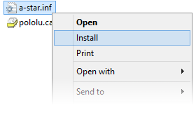
- Download the A-Star Windows Drivers (7k zip) and extract the ZIP file to a temporary folder on your computer. (These files are also available in the “drivers” directory from the A-Star repository on GitHub.)
- Open the “a-star-windows” folder. Right-click on “a-star.inf” and select “Install”.
 |
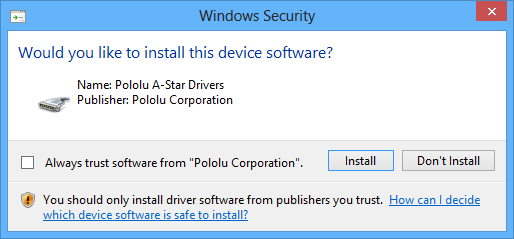
- Windows will ask you whether you want to install the drivers. Click “Install” (Windows 10, 8, 7, and Vista) or “Continue Anyway” (Windows XP).
 |
- Windows will not tell you when the installation is complete, but it should be done after a few seconds.
Windows 11, Windows 10, Windows 8, Windows 7, and Windows Vista users: After installing the drivers, your computer should automatically recognize the device when you connect it via USB. No further action from you is required. However, the first time you connect an A-Star device to your computer, Windows will take several seconds to recognize the device and configure itself properly. The first time you program the device, Windows will again take several seconds to recognize the A-Star USB bootloader, and this could cause the programming operation to fail the first time. Also, Windows will need to re-recognize the device and the bootloader if you connect the board to another USB port that it has not been connected to before.
Windows XP users: After installing the drivers, you will need to follow steps 5–9 for each new A-Star device you connect to your computer. You will also need to follow these steps the first time you attempt to program the device in order to make Windows recognize the bootloader, and when you connect the device to a different USB port that it has not been connected to before.
- Connect the device to your computer’s USB port.
- When the “Found New Hardware Wizard” is displayed, select “No, not this time” and click “Next”.
- On the second screen of the “Found New Hardware Wizard”, select “Install the software automatically” and click “Next”.
- Windows XP will warn you again that the driver has not been tested by Microsoft and recommend that you stop the installation. Click “Continue Anyway”.
- When you have finished the “Found New Hardware Wizard”, click “Finish”.
COM port details
After installing the drivers and plugging in an A-Star, in the “Ports (COM & LPT)” category of the Device Manager, you should see a COM port for the A-Star’s running sketch named “Pololu A-Star 32U4”.
You might see that the COM port is named “USB Serial Device” in the Device Manager instead of having a descriptive name. This can happen if you are using Windows 10 or later and you plugged the A-Star into your computer before installing our drivers for it. In that case, Windows will set up your A-Star using the default Windows serial driver (usbser.inf), and it will display “USB Serial Device” as the name for the port. The port will still be usable, but it will be hard to tell if it is the right one because of the generic name shown in the Device Manager. We recommend fixing the names in the Device Manager by right-clicking on each “USB Serial Device” entry, selecting “Update Driver Software…”, and then selecting “Search automatically for updated driver software”. Windows should find the drivers you already installed, which contain the correct name for the port.
If you are using Windows 10 or later and choose not to install the drivers, the A-Star will still be usable. To tell which “USB Serial Device” in your Device Manager is the A-Star, double-click on each one and look at the “Hardware Ids” property in the “Details” tab. An A-Star running a sketch will have the ID USB\VID_1FFB&PID_2300&MI_00, while an A-Star in bootloader mode will have the ID USB\VID_1FFB&PID_0101.
If you want to change the COM port numbers assigned to your A-Star, you can do so using the Device Manager. Double-click a COM port to open its properties dialog, and click the “Advanced…” button in the “Port Settings” tab.
6.2. Programming using the Arduino IDE
 |
Programming the A-Star 32U4 from the Arduino IDE. |
|---|
Our 32U4 family of boards can be programmed from the popular Arduino integrated development environment (IDE). The Arduino IDE is a cross-platform, open source application that integrates a C++ code editor, the GNU C++ compiler, and a program upload utility. To get started programming your device with the Arduino IDE (version 1.6.4 or later), follow these steps:
- Download the Arduino IDE from the Arduino Download page, install it, and start it.
- In the Arduino IDE, open the File menu (Windows/Linux) or the Arduino menu (macOS) and select “Preferences”.
- In the Preferences dialog, find the “Additional Boards Manager URLs” text box (highlighted in the picture below). Copy and paste the following URL into this box:
https://files.pololu.com/arduino/package_pololu_index.json
If there are already other URLs in the box, you can either add this one separated by a comma or click the button next to the box to open an input dialog where you can add the URL on a new line.
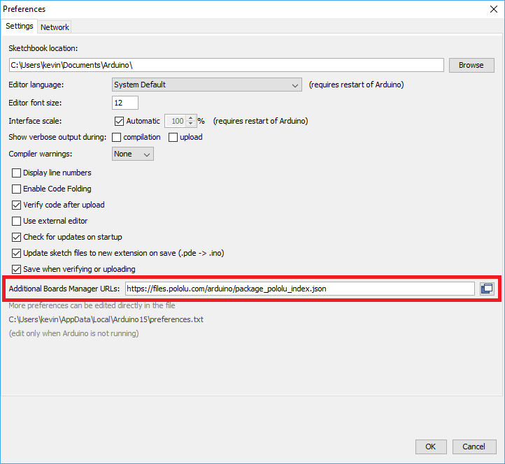 |
Adding a Boards Manager index for Pololu boards in the Arduino IDE’s Preferences dialog. |
|---|
- Click the “OK” button to close the Preferences dialog.
- In the Tools > Board menu, select “Boards Manager…” (at the top of the menu).
- In the Boards Manager dialog, search for “Pololu A-Star Boards”.
- Select the “Pololu A-Star Boards” entry in the list, and click the “Install” button.
- After the installation finishes, click the “Close” button to close the Boards Manager dialog.
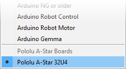
- In the Tools > Board menu, select the “Pololu A-Star 32U4” entry. If you do not see your device listed in the Board menu, try restarting the Arduino IDE.
 |
Selecting the Pololu A-Star 32U4 in the Boards menu. |
|---|
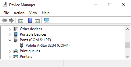
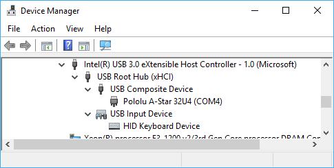
- In the Tools > Port menu, select the port for the device. On Windows you can determine what COM port the device is assigned to by looking at the “Ports (COM & LPT)” section of the Device Manager. On Linux, the port name will begin with “/dev/ttyACM”. On Mac OS X, the port name will begin with “/dev/tty.usbmodem”.
 |
Windows 10 Device Manager showing the A-Star’s virtual COM port. |
|---|
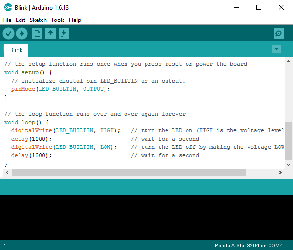
- Open up the “Blink” Arduino example, which can be found under File > Examples > 01.Basics > Blink. The code in this example will blink the yellow LED. When you select the Blink example, a new Arduino IDE window will open up. It is OK to close the first window.
 |
Selecting the Blink example in the Arduino IDE. |
|---|
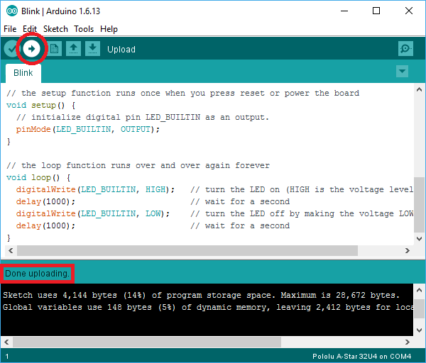
- Press the “Upload” button to compile the sketch and upload it to the device. If everything goes correctly, you will see the message “Done uploading” appear near the bottom of the window. If you are using Windows and you have not previously programmed an A-Star device on this USB port, then Windows might take several seconds to recognize the A-Star bootloader. The bootloader times out after 8 seconds and goes back to running the sketch, so the upload might fail if Windows does not recognize it quickly enough. If this happens, try again. If you are using Windows XP and have not programmed an A-Star on this USB port, you will have to go through the Found New Hardware Wizard again as described in the previous section, but the second time you try to upload it should work. If the Arduino IDE has trouble connecting to the port or using it, try unplugging the device, closing any programs that might be using the serial port, restarting the Arduino IDE, and then plugging the device back in.
 |
Uploading a sketch to the A-Star using the Arduino IDE. |
|---|
- If you uploaded the Blink sketch, then the yellow LED should be blinking once every two seconds. However, we ship some A-Stars with that same example already programmed onto it, so you might not be convinced that anything has changed. Try changing the delay values in the sketch to something else and uploading again to see if you can change the speed of the LED.
The A-Star 32U4 boards are similar enough to the Arduino Leonardo that you do not actually have to install the add-on. If you want to, you can just select the “Arduino Leonardo” board in the Arduino IDE. Note that if you upload a sketch to the device this way, your computer will then recognize it as a Leonardo (for example, its entry in the Windows Device Manager will display “Arduino Leonardo”).
After you succeed in programming your device from the Arduino IDE, there are many resources you can use to learn more:
- The Arduino IDE has many examples that can run on A-Stars.
- The Arduino website has a Language Reference, a wiki called the The Arduino Playground, and other resources.
- The A-Star 32U4 boards are similar to the Arduino Leonardo and Arduino Micro, so you can search the Internet for relevant projects that use one of those boards.
- The Related Resources section lists many more resources.
Disabling ModemManager in Linux
If you are using Linux and have trouble following the instructions above, your issue might be caused by a program called ModemManager. This program automatically connects to serial ports and sends modem commands to them, interfering with other software using those ports. You can run ps ax | grep -i Modem to see if ModemManager is running. On Ubuntu, the command to permanently disable ModemManager is:
sudo systemctl disable ModemManager
6.3. Programming using avr-gcc and AVRDUDE
This section explains how to program our 32U4 family of boards using the avr-gcc toolchain and AVRDUDE. This section is intended for advanced users who do not want to use the Arduino IDE as described in the previous section.
Getting the prerequisites
If you are using Windows, we recommend downloading WinAVR, which contains the avr-gcc toolchain and a command-line utility called AVRDUDE that can be used to upload programs to the A-Star bootloader. If the version of GNU Make that comes with WinAVR crashes on your computer, we recommend using the Pololu version of GNU Make.
If you are using macOS, we recommend first installing Homebrew. Then run the following commands to install AVRDUDE and homebrew-avr:
brew install avrdude
xcode-select --install
brew tap osx-cross/avr
brew install avr-gcc
If you are using Linux, you will need to install avr-gcc, avr-libc, and AVRDUDE. Ubuntu users can get the required software by running:
sudo apt-get install gcc-avr avr-libc avrdude
After you have installed the prerequisites, open a command prompt and try running these commands to make sure all the required utilities are available:
avr-gcc -v
avr-objcopy -V
make -v
avrdude
If any of those commands fail, make sure the desired executable is installed on your computer and make sure that it is in a directory listed in your PATH environment variable.
Compiling an example program
Copy the following code to a file named “main.c”:
#define F_CPU 16000000
#include <avr/io.h>
#include <util/delay.h>

int main()
{
  DDRC |= (1 << DDC7);    // Make pin 13 be an output.
  while(1)
  {
    PORTC |= (1 << PORTC7);   // Turn the LED on.
    _delay_ms(500);
    PORTC &= ~(1 << PORTC7);  // Turn the LED off.
    _delay_ms(500);
  }
}
In the same folder, create a file named “Makefile” with the following contents:
PORT=\\\\.\\GLOBALROOT\\Device\\USBSER000
MCU=atmega32u4
CFLAGS=-g -Wall -mcall-prologues -mmcu=$(MCU) -Os
LDFLAGS=-Wl,-gc-sections -Wl,-relax
CC=avr-gcc
TARGET=main
OBJECT_FILES=main.o

all: $(TARGET).hex

clean:
	rm -f *.o *.hex *.obj *.hex

%.hex: %.obj
	avr-objcopy -R .eeprom -O ihex $< $@

%.obj: $(OBJECT_FILES)
	$(CC) $(CFLAGS) $(OBJECT_FILES) $(LDFLAGS) -o $@

program: $(TARGET).hex
	avrdude -p $(MCU) -c avr109 -P $(PORT) -U flash:w:$(TARGET).hex
Make sure that the PORT variable in the Makefile is the name of the device’s virtual serial port. In Windows, \\\\.\\GLOBALROOT\\Device\\USBSER000 should work if the A-Star is the only USB device connected that is using the usbser.sys driver, but you can change it to be the actual name of the COM port (e.g. COM13).
In a command prompt, navigate to the directory with the Makefile and main.c. If you run the command make, the code should get compiled and produce a file named “main.hex”.
Programming
To program the A-Star device, you will need to get it into bootloader mode first. One way to do this is to reset the AVR twice within 750 ms. Most of the boards in our 32U4 family have a reset button that can be used to reset the board. On any of our 32U4 family of boards, a pushbutton can be connected between the GND and RST pins to serve as a reset button, or you can use a wire. Once the device is in bootloader mode, quickly run the command make program to program it. If you wait longer than 8 seconds, the A-Star bootloader will exit and the AVR will go back to running the user program.
7. A-Star 32U4 Arduino library
The A-Star 32U4 can be programmed from the Arduino IDE as described in the preceding sections.
To help interface with all the on-board hardware on the A-Star 32U4, we provide the AStar32U4 library. The AStar32U4 library documentation provides detailed information about the library, and the library comes with several example sketches.
If you are using version 1.6.2 or later of the Arduino software (IDE), you can use the Library Manager to install this library:
- In the Arduino IDE, open the “Sketch” menu, select “Include Library”, then “Manage Libraries…”.
- Search for “AStar32U4”.
- Click the AStar32U4 entry in the list.
- Click “Install”.
If this does not work, you can manually install the library:
- Download the latest release archive from GitHub and decompress it.
- Rename the folder “a-star-32u4-arduino-library-master” to “AStar32U4”.
- Move the “AStar32U4” folder into the “libraries” directory inside your Arduino sketchbook directory. You can view your sketchbook location by opening the “File” menu and selecting “Preferences” in the Arduino IDE. If there is not already a “libraries” folder in that location, you should make the folder yourself.
- After installing the library, restart the Arduino IDE.
After you install the AStar32U4 library, you can learn more about it by trying the included example sketches and by reading the AStar32U4 library documentation.
8. The A-Star 32U4 USB interface
Our 32U4 family of boards are based on a single ATmega32U4 AVR microcontroller that runs the user program and also handles the USB connection to the computer. The AVR has a full-speed USB transceiver built into it and can be programmed to present almost any type of USB device interface to the computer.
USB is an asymmetric system that consists of a single “host” connected to multiple “devices”. The host is typically a personal computer. The ATmega32U4 can only act as a USB device, so an A-Star device cannot be connected to other USB devices like mice and keyboards; it can only be connected to a host such as your computer.
Programming an ATmega32U4 board using the Arduino IDE as described earlier will automatically configure it as a composite device with a single virtual serial port. If you program the microcontroller with an Arduino sketch that implements another USB device class, like HID or MIDI, you will see additional child devices as well.
On a Windows computer, you can see the virtual serial port by going to your computer’s Device Manager and expanding the “Ports (COM & LPT)” list. You should see a COM port labeled “Pololu A-Star 32U4”. In parentheses after the name, you will see the name of the port (e.g. “COM3” or “COM4”). Windows will assign a different COM port number to the device depending on what USB port you plug it into and whether it is in bootloader mode or not. If you need to change the COM port number assigned to the A-Star, you can do so using the Device Manager. Double-click on the COM port to open its properties dialog, and click the “Advanced…” button in the “Port Settings” tab. From this dialog you can change the COM port assigned to the device.
|
Windows 10 Device Manager showing the A-Star’s virtual COM port. |
|---|
On a Windows computer, you can see the rest of the USB interface by going to the Device Manager, selecting View > Devices by connection, and then expanding entries until you find the “Pololu A-Star 32U4” COM port. Near it, you should see the parent composite device.
 |
The Windows 10 Device Manager in “Devices by connection” mode, showing that the A-Star is a composite device. |
|---|
On a Linux computer, you can see details about the USB interface by running lsusb -v -d 1ffb: in a Terminal. The virtual serial port can be found by running ls /dev/ttyACM* in a Terminal.
On a Mac OS X computer, the virtual serial port can be found by running ls /dev/tty.usbmodem* in a Terminal.
You can send and receive bytes from the virtual serial port using any terminal program that supports serial ports. Some examples are the Serial Monitor in Arduino IDE, the Pololu Serial Transmitter Utility, Br@y Terminal, PuTTY, TeraTerm, Kermit, and GNU Screen. Many computer programming environments also support sending and receiving bytes from a serial port.
9. The A-Star 32U4 Bootloader
Our 32U4 family of boards come with a USB bootloader that can be used in conjunction with the Arduino IDE or AVRDUDE to load new programs onto the device. This section documents some technical details of the bootloader for advanced users who want to better understand how it works. If you just want to get started using your device, it is fine to skip this section.
The A-Star 32U4 Bootloader is based on the Caterina bootloader, which is the bootloader used on the Arduino Leonardo, Arduino Micro and several other ATmega32U4 boards. The bootloader is open source and its source code is available on GitHub. The bootloader occupies the upper four kilobytes of the ATmega32U4’s program memory, leaving 28 KB for the user program. The bootloader’s USB interface consists of a single virtual serial port that accepts the programming commands defined in AVR109. The bootloader always runs first immediately after the AVR is reset.
Startup logic
The main difference between the A-Star 32U4 Bootloader and Caterina is in the startup logic. This is the part of the bootloader that runs immediately after the AVR is reset, and it decides whether to run the user program or run the rest of the bootloader. The startup logic of the Caterina bootloader is designed so that when the RST line goes low, the bootloader will run. This means that if you want to restart your program using the RST line, it will take 8 seconds before the bootloader times out waiting for an upload and the sketch starts.
The A-Star 32U4 Bootloader has different startup logic that allows you to use the RST line to reset the board with a smaller delay. If the RST line goes low once, the user program will run after a 750 ms delay. If the RST line goes low twice within 750 ms, then the bootloader will run. (This behavior is the same as on boards like SparkFun’s Pro Micro.)
The start-up logic of the A-Star 32U4 Bootloader is shown in the flowchart below:
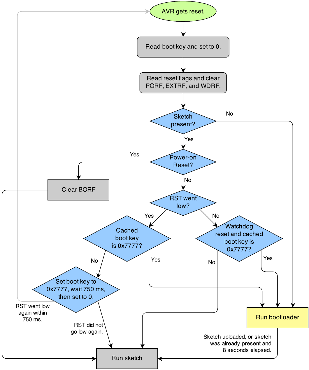 |
The startup logic for the A-Star 32U4 bootloader. |
|---|
Brown-out detection
Unlike many other ATmega32U4 boards, our 32U4 family of boards have brown-out detection enabled. The brown-out threshold is 4.3 V, and if the voltage on VCC goes below this then the AVR will reset. The bootloader was designed so that the user program can detect brown-out resets. To do so, check to see if the BORF bit in the MCUSR register is set, and then clear it later. Here is some example code you could put in your setup function for detecting brown-out resets:
pinMode(13, OUTPUT);
if (MCUSR & (1 << BORF))
{
  // A brownout reset occurred.  Blink the LED
  // quickly for 2 seconds.
  for(uint8_t i = 0; i < 10; i++)
  {
    digitalWrite(13, HIGH);
    delay(100);
    digitalWrite(13, LOW);
    delay(100);
  }
}
MCUSR = 0;
10. Reviving an unresponsive A-Star
In order to load a new program onto your A-Star 32U4 device, you will need to get it into bootloader mode and send programming commands to it over its virtual serial port using appropriate software. If you are programming the device from the Arduino IDE, the sketch loaded onto the device will generally support a special USB command for putting it in bootloader mode, and the Arduino IDE sends that command automatically when you click the Upload button. However, you might find yourself in a situation where the device is unresponsive and that method will not work. This can happen for two reasons:
- You accidentally loaded a malfunctioning program onto the device that is incapable of responding to the special USB command. For example, your program might be stuck in an infinite loop with interrupts disabled.
- You loaded a program which uses a non-standard type of USB interface or no USB interface.
The following sections provide different procedures you can use to revive your device.
10.1. Reviving using the Arduino IDE
This section explains three special methods for programming an A-Star (or another of our 32U4 family of boards) using the Arduino IDE in case your usual method of programming is not working.
Reset button
If you have an A-Star 32U4 Micro, you should connect a momentary pushbutton between the GND and RST pins to serve as a reset button. Other boards in our 32U4 family have a reset button you can use. Alternatively, you can use a wire to temporarily connect GND and RST together instead of using a reset button.
Resetting the board twice within 750 ms makes the board go into bootloader mode. The bootloader will exit after 8 seconds and try to run the sketch again if it has not started receiving programming commands. To revive the device, you need to make sure you start sending it programming commands before the 8-second period is over.
In bootloader mode, the yellow LED (the one labeled LED 13) fades in and out. It is useful to look at this LED so you can know what mode the microcontroller is in. Also, we recommend enabling verbose output during upload using the Arduino IDE’s “Preferences” dialog. Looking at the LED and looking at the verbose output during the following procedures will help you understand what is going on.
The substitute port method
This method has been tested on Arduino 1.8.19 and Arduino 2.0.3 but requires extra hardware.
- Connect a substitute serial port device to your computer. This should be a device that is recognized by the Arduino IDE as a serial port, but it should not be an A-Star 32U4, Arduino Leonardo, Arduino Micro, or any other device that disappears and reappears as a new device when a piece of software like the Arduino IDE opens the port, sets the baud rate to 1200, and then closes the port. It should also be a device that will not cause any problems if it receives data from the Arduino IDE. Here are some examples of substitute serial port devices:
- A USB-to-serial adapter such as the CP2102N
- A Pololu USB AVR Programmer v2.1
- An Arduino Uno R3
- A non-USB serial port such as
/dev/ttyS0on a Raspberry Pi
- Connect the 32U4 device to your computer via USB.
- In the “Tools” menu, open the “Board” sub-menu and select “Pololu A-Star 32U4”.
- In the “Tools” menu, open the “Port” sub-menu and select the substitute serial port.
- Click the Upload button. The Arduino IDE will compile your sketch and start uploading it.
- As soon as the box near the bottom of the IDE says “Uploading…”, reset the board twice to get into bootloader mode.
If you wait longer than 10 seconds to get the board into bootloader mode in the last step, the Arduino IDE will give up waiting for the bootloader’s serial port and instead attempt to send programming commands to the substitute serial port.
The uploading-before-bootloader method
The goal of the uploading-before-bootloader method is to select a non-existent serial port in the Arduino IDE and then make sure the Arduino IDE enters the uploading phase before the microcontroller goes into bootloader mode. This method has been tested on Arduino 1.8.19. This method does not work on Arduino 2.0.0 or 2.0.3 (and probably does not work on any 2.x versions) because those versions of the IDE give a fatal error message if the selected serial port is not present at the beginning of the uploading phase (“Failed uploading: no upload port provided”).
- Connect the 32U4 device to your computer via USB.
- In the “Tools” menu, open the “Board” sub-menu and select “Pololu A-Star 32U4”.
- In the “Tools” menu, open the “Port” sub-menu and check to see if any ports are selected. If the “Port” menu is grayed out or no ports in it are selected, that is good, and you can skip to step 6.
- Reset the board twice to get the board into bootloader mode. While the board is in bootloader mode, quickly select the new serial port that corresponds to the bootloader in the “Port” menu.
- After 8 seconds, the bootloader will exit and attempt to run the sketch again. Wait for the bootloader to exit. Verify that either the “Port” menu is grayed out or no ports in it are selected.
- Click the Upload button. The Arduino IDE will compile your sketch and start uploading it.
- As soon as the box near the bottom of the IDE says “Uploading…”, reset the board twice to get into bootloader mode.
The Arduino IDE will stay in the uploading phase for 10 seconds, waiting for a new serial port to appear. Once the serial port of the bootloader appears, the Arduino IDE will connect to it and send programming commands.
The bootloader-before-uploading method
This method has been tested on Arduino 2.0.3 but the timing requirements of the last step are so tight that the method might be impossible on slower computers.
- Connect the 32U4 device to your computer via USB.
- In the “Tools” menu, open the “Board” sub-menu and check to see if the “Pololu A-Star 32U4 (bootloader port)” entry is visible. If this entry is visible, you can skip to step 6.
- Using a text editor, open the file named boards.txt that provides the “Pololu A-Star” board entries. In Windows, you can typically find this file in %LocalAppData%\Arduino15\packages\pololu-a-star\hardware\avr\. In Linux, you can typically find this file in ~/.arduino15/packages/pololu-a-star/hardware/avr/. On macOS, you can typically find this file in ~/Library/Arduino15/packages/pololu-a-star/hardware/avr/. If you installed the boards manually instead of using the Board Manager, you can find it in [sketchbook location]/hardware/pololu/avr.
- In the boards.txt file that you opened, find the lines at the bottom of the file that start with
#a-star32U4bp. Uncomment each of those lines by deleting the “#” character, and then save the file. - Close the Arduino IDE and restart it.
- In the “Tools” menu, open the “Board” sub-menu and select “Pololu A-Star 32U4 (bootloader port)”. This entry is configured so that the Arduino IDE will send programming commands directly to selected serial port, instead of trying to send a special USB command to the port to get it into bootloader mode and then waiting for the new port to appear. By selecting this entry, the timing of the programming process below becomes easier, especially on Windows.
- Prepare the computer to show you a list of its virtual serial ports. If you are using Windows, this means you should open the Device Manager. If you are on Linux or macOS, this means you should open a Terminal and type the command
ls /dev/tty*but do not press enter until the board is in bootloader mode in the next step. - Reset the board twice to get the board into bootloader mode. While it is in bootloader mode, quickly look at the list of serial ports provided by your operating system in order to determine what port the bootloader is assigned to.
- In the Arduino IDE, click the “Verify” button to compile your sketch. This could make the timing easier during the next step.
- Reset the board twice to get the board into bootloader mode again. As soon as the yellow LED starts fading in and out, indicating the board is in bootloader mode, quickly select the serial port of the bootloader in the Arduino IDE (in Tools > Port) and then quickly click the Upload button.
The Arduino IDE will compile your sketch and then upload it to the selected serial port.
If the compilation of the sketch takes longer than 8 seconds, then this procedure will fail because the bootloader will time out and start trying to run the malfunctioning sketch again. If that happens, try the last two steps again using a simpler sketch such as the Blink example that can be found under File > Examples > 01.Basics > Blink. Also, make sure your computer is not too busy performing other tasks in the background, and make sure you performing the last step as fast as you can.
This method can also work in the older Arduino 1.8.19 with some modifications. You should select the correct port in the Port menu prior to the last step (e.g. by temporarily putting the board into bootloader mode and then selecting it). This makes the timing of the last step easier because you can just click the “Upload” button instead of clicking three times to select a port. Also, if the timing of the last step is still too tight, you can actually click Upload before putting the board into bootloader mode, but you need to get the board into bootloader mode while the IDE is still compiling, before the upload phase begins. (Neither of these optimizations are possible on Arduino 2.0.3 because it erases your serial port selection if the port disappears.) However, if you are using Arduino 1.8.19, the uploading-before-bootloader method documented above is probably easier.
After reviving your device, be sure to change the Board setting back to “Pololu A-Star 32U4” and select the right Port.
10.2. Reviving using AVRDUDE
This section explains a special method for reviving an A-Star (or another of our 32U4 family of boards) using the command-line utility AVRDUDE in case your usual method of programming is not working. AVRDUDE stands for “AVR Downloader/UploaDEr”, and it is compatible with the A-Star bootloader.
If you have an A-Star 32U4 Micro, you should connect a momentary pushbutton between the GND and RST pins to serve as a reset button. Other boards in our 32U4 family have a reset button you can use. Alternatively, you can use a wire to temporarily connect GND and RST together instead of using a reset button.
- Connect the device to your computer via USB.
- Prepare the computer to show you a list of its virtual serial ports. If you are using Windows, this means you should open the Device Manager. If you are on Linux or Mac OS X, this means you should open a Terminal and type the command
ls /dev/tty*but do not press enter until the board is in bootloader mode in the next step. - Press the reset button twice within 750 ms to make the AVR go into bootloader mode. You should see the yellow LED fading in and out when the AVR is in bootloader mode. While it is in bootloader mode, quickly look at the list of serial ports provided by your operating system in order to determine what port the bootloader is assigned to.
- Type the following command in your terminal and replace COM4 with the name of the bootloader’s serial port, but do not press enter yet. This command will erase the malfunctioning program on the device but preserve the bootloader.
avrdude -c avr109 -p atmega32U4 -P COM4 -e
- Press the reset button twice within 750 ms to make the AVR go into bootloader mode.
- Quickly run the command you typed previously. The command needs to be run within 8 seconds of starting the bootloader, or else the bootloader will exit and try to run the malfunctioning program again.
By following the instructions above, the malfunctioning program on the device will be erased and the device will stay in bootloader mode indefinitely. You can now load another program onto it using the Arduino IDE or AVRDUDE.
11. Related Resources
To learn more about using the Pololu A-Star boards, see the following list of resources:
- The Arduino IDE has many examples that can run on the A-Stars.
- The Arduino website has a Language Reference, a wiki called the The Arduino Playground, and other resources.
- The A-Star boards are similar to the Arduino Leonardo and Arduino Micro, so you can search the Internet for relevant projects that use one of those boards.
- Atmel’s ATmega32U4 documentation has the ATmega32U4 datasheet and many related documents.
- AVR Libc Home Page: this page documents the standard library of functions that you can use with GNU C and C++ compilers for the AVR.
- A-Star 32U4 Arduino library
- AStar32U4 library documentation
- LUFA – the Lightweight USB Framework for AVRs
- WinAVR
- Microchip Studio for AVR and SAM Devices
- AVRDUDE
- AVR Freaks
Datasheets for some of the components found on the A-Star 32U4 boards are available below (not all components apply to every board):
- Texas Instruments TPS2113A power multiplexer datasheet (1k redirect)
- Texas Instruments DRV8838 motor driver datasheet (1k redirect)
- Maxim MAX14870 motor driver datasheet (492k pdf)
Finally, we would like to hear your comments and questions on the A-Star section of the Pololu Robotics Forum!
Related products


Home | Forum | Blog | Support | Ordering Information | Lists | Distributors | BIG Order Form | About | Contact
© 2001–2026 Pololu Corporation
