Pololu Blog »
Brandon's line following robot: The Chariot
 |
Deciding where to start
For the recent LVBots line following competition, my first instinct was to try to come up with some unique alternative design for a robot that would be competitive with the traditional differential drive robots. However, I knew the winning robot from the last LVBots line following competition (Mostly Red Racer) would be returning, and it had an impressive time to beat. I also remembered spending so much time designing and assembling the hardware for my last line following robot, that I ended up not having enough time to tune the PID coefficients and get the performance I was hoping for. After brainstorming a few ideas, I ended up deciding to keep it simple and make sure I had enough time to get a robot I was happy with, which I ultimately named “The Chariot” because of its shape. The Chariot ended up winning second place in the competition, which I was very happy with. Instead of focusing this blog post on how you can make your own version of The Chariot, I will try to explain my thought process throughout the design and build process. In other words, my hope is that after reading through this post, it will be clear why I chose the parts that I did.
Choosing parts
The first thing I decided was how I was going to power The Chariot. When designing a line following robot, one thing to keep in mind is that the performance can change significantly when your battery voltage changes (e.g. when the batteries are recharged or drained). A great way to prevent this inconsistency is to use a voltage regulator. I chose to use a regulator from the D24V25Fx family of step-down regulators, which allow for output current of around 2.5 A and come in a variety of output voltages from 3.3 V to 9 V. I ended up choosing the 7.5 V D24V25F7 regulator because it fit well with the rest of my system. I also had an extra 3S LiPo battery that I decided to use as my main power source.
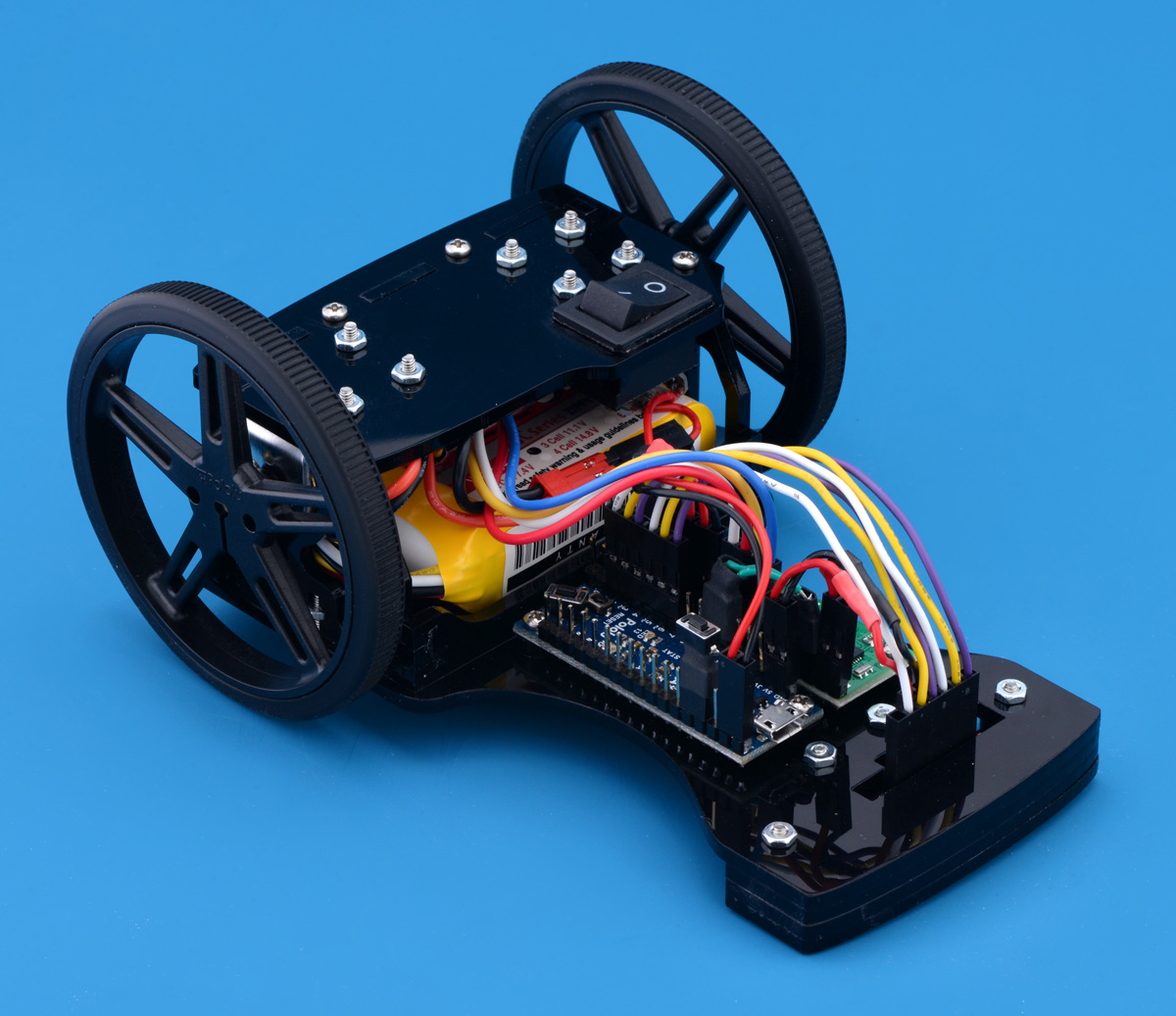
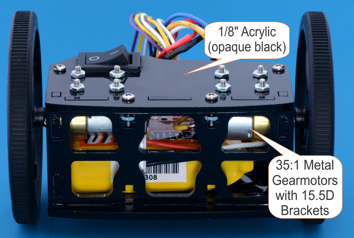
I used a pair of our 35:1 Metal Gearmotors 15.5Dx30L mm and compatible mounting brackets. These motors have a free-run speed of about 575 RPM at 7.5V and plenty of torque for my lightweight robot. Also, the 3mm-diameter D-shaped output shaft is compatible with our Pololu Wheels. I also used a lightweight 3/8″ plastic ball caster as a third contact point. After some quick calculations, I determined the 70 mm wheels should give my robot a theoretical maximum free-run speed of around 2 m/s. I used the speed of a 3pi robot, which is roughly 1m/s, as a base-line goal to beat.
 |
 |
Next, I looked for a motor driver. I wanted a small dual motor driver that did not use a lot of I/O pins to drive from a microcontroller. The Qik 2s9v1 Dual Serial Motor Controller fit these criteria and worked great with the motors I chose. Since the Qik accepts serial commands and has an Arduino library, it was easy to integrate into my system. For my main microcontroller, I used the A-Star 32U4 Mini LV. This Arduino-compatible programmable controller is based on the ATmega32U4 from Atmel and has an onboard switching step-up/step-down regulator that allows it to be powered efficiently from 2.7 V to 11.8 V. It is also small and uses a Micro-B USB connection for programming. The only part left to pick was the line sensors. For that, I used a QTR-8RC Reflectance Sensor Array, but since I did not need all 8 sensors in the array, I broke the board into two parts, leaving me with a 6 sensor array for The Chariot and an extra 2 sensor board for a later project.
 |
 |
Designing a chassis
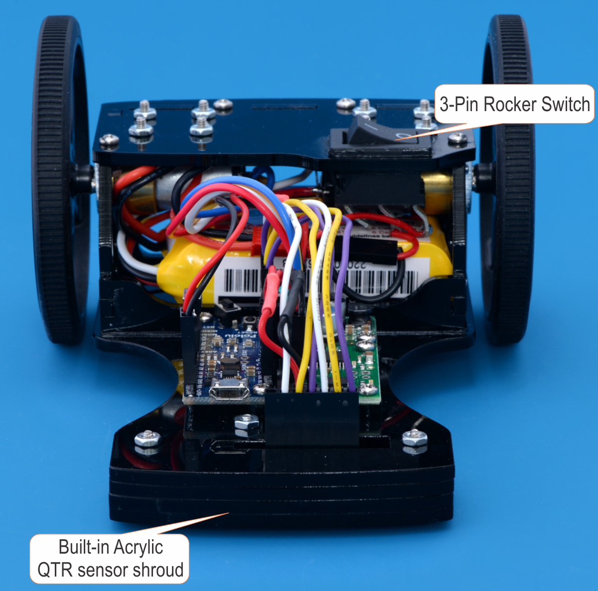
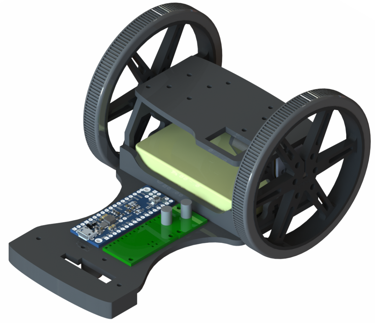
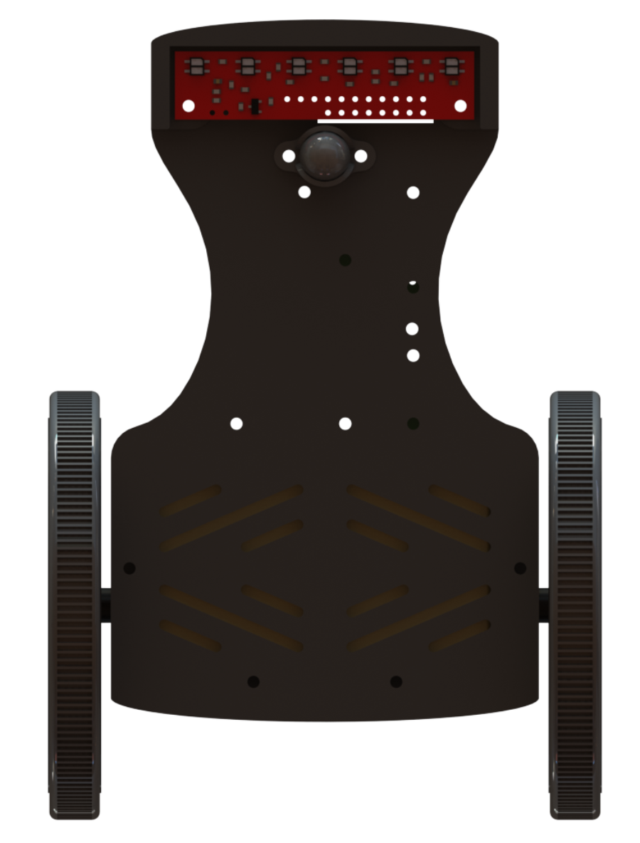
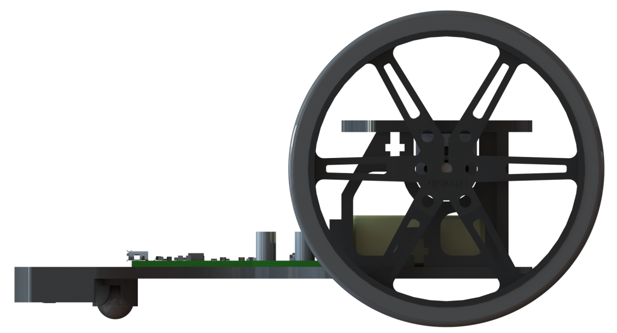
I designed the chassis for my robot using SolidWorks. Using 1/8″ thick acrylic from our Custom Laser Cutting Service allowed The Chariot to be sturdy but lightweight (about 210 g including components and hardware). I knew from past experience that having too much weight extended in front of the robot makes it difficult to control during turns, so I kept my battery located under the motors. To allow easy access to the battery, I used a few t-slots intended for #2-56 screws and nuts to hold it all together. If you are designing something like this in acrylic, I recommend reading this How to make snug joints in acrylic guide, which has some useful tips. I also remembered robots using IR sensors having problems with interference from the lighting in the competition room during a few of the previous competitions. To help prevent this problem, I designed a shield around where the QTR sensor array was mounted. The pictures below show the rendered model I designed in SolidWorks.
 |
|
|
Following a line
Unlike the previous line following competition, I had enough time to tune my robot to a performance I was comfortable with (not too fast that it was unreliable, but fast enough to be competitive). I even had time to add a second button on the day of the competition to program in an “aggressive mode” and a “conservative mode”. This allowed me to have a faster (but less reliable) setting for The Chariot, just in case I felt like it needed a small boost during the competition. While it was a nice feature to have, it was a little too unreliable. After losing an early race because The Chariot missed a turn and lost the line, I stuck with the conservative option.
The competition was a bracket-style, double elimination, line following race. Two robots would face-off for 3 laps around mirrored courses, clock their times, then switch courses. The one with the single fastest time won the heat. That format allowed a more exciting structure since there were head-to-head races, while also letting us directly compare robots with others we might not have raced against. For more information about the rules, see the LVBots line following rules. The Chariot ended up in the final race against last year’s champion, Ben’s Mostly Red Racer. Coming into the final race from the loser’s bracket meant that the Chariot had to win twice to be declared the winner, but the Mostly Red Racer was too fast, with three laps clocking in 24.4 seconds and an average speed of 1.20 m/s. The Chariot was close behind, getting second place with a time of 25.1 seconds and an average speed of 1.17 m/s. Overall, I am very happy with the second place result, and while I did not beat the defending champion, I did beat my personal best.
Related products


-
Jon's line following robot: Usain Volt 2.0
- 4 May 2015Like other developers and engineers here, I made a robot for the LVBots Line Following Contest. This post describes my robot, Usain Volt 2.0, and...
-
Claire's line following robot: Oddish
- 7 May 2015A few weeks ago the local robotics club, LVBots, hosted a line following competition here at Pololu, and like many of the engineers here, I built a...
19 comments


I am glad you like my line follower. It is not clear to me what part of the robot you are requesting more details about, but if you are mostly interested in the line following code, I would suggest looking at our example line follower code for the Zumo Robot for Arduino, v1.2 (which is what my code is based on).
I have never made an advanced line following robot quite like the one you described. I recommend getting the basic line following working before connecting additional sensors.
Please let me know if I misunderstood your request or if you have more specific questions about my robot.
By the way, if you have more general questions about building your line follower, you might try posting them on our forum to see if anyone there has suggestions.
-Brandon

......sauvikray001@gmail.com...
I do not currently have my code available; however, as I mentioned in my last comment, my code is based on our example line follower code for the Zumo Robot for Arduino, V1.2. Other than converting the motor commands into the corresponding TTL serial commands for the Qik 2s9v1 motor controller, the biggest change I made to that code was probably tuning the PID coefficients. Since this varies for every system, I suspect my code would not be any more helpful than that sample code.
I see you also posted a request for help on our forum. That seems like a more appropriate place to continue the discussion if you have more questions.
-Brandon

Prodigydx@hotmail.co.za
I am glad you are interested in my design! I made my design files for the laser-cut pieces available via Thingiverse; you can use this link to access those files when they are available (this is my first time uploading and publishing a creation on Thingiverse, and they require a minimum wait time of 24 hours between account creation and publishing your first creation, so you might have to wait until around this time tomorrow).
For the mechanical components, you can find 3D models for the motor and motor bracket on their respective product pages. We do not currently have models available for the wheels or ball caster, although it is something we are looking into. For now, you can find dimension diagrams for them on their respective product pages. Please let me know if I left something out or you have any additional questions.
Brandon

Thank you so much. I 3D printed it and it looks amazing. My collegues were impressed so i referred them to your blog.
Much appreciated for your help.
James

Any tips on how to tune the PID control? What order to tune them, things to look out for while watching the robot run around the track? Do I tune it up slow and then increase the speed on the PWM and retune. How much swing would you leave either side of the base PWM, tune in the middle 128 and allow 0 to 255 to be min and max or close the range down a bit. Maybe increase the voltage on the motors.
Any help is much appreciated.
Thanks.
The Chariot and Mostly Red Racer (the winner of the competition) both used PD control (no integral). The integral term is useful for counter-acting some external force consistently working against the robot. When following a line, you do not typically have that kind of constant force working against your robot's goal, so in most cases you can simplify by leaving out the Integral term.
I find it easiest to start tuning at a somewhat slow speed and gradually increase your speed once your P and D coefficients are working fairly well. At slow enough speeds, you probably don't need a D term at all, especially for a relatively straight line. If you want to be able to drive quickly around sharper turns, you will need your P term to be large, which will likely cause an overshoot. This is where the D term comes in to compensate. Essentially, the D term takes a history of the error and reacts to the change accordingly. If the error is getting smaller, it acts to weaken your robot's response to avoid overshoot. Similarly, if the error is getting bigger, the D term should act to increase your robot's response. There are a lot of good tips for tuning in Ben's posts in this thread. You might consider creating your own thread on our forum if you run into more specific questions when tuning your robot.
Brandon

I'm currently building my own line following robot based on your design but there is something that I can't figure out still...How exactly did you connect the battery to the switch? As I understand from the photos included and my basic understanding of circuitries you used a connector to plug the battery to and then you soldered the positive end of the connector to the rocker switch and another wire from the switch to connect it to the microcontroller and soldered one more wire to the connector and connected it to the microcontroller as ground? Is that correct? Additionally, as you don't mention such thing and I can't see it in the photos either, you did not use any kind of low voltage cut off circuitry to protect the LiPo battery,right? In general, how did you take care/maintained the battery itself?
Any additional tip or suggestion would be greatly appreciated.
Thanks in advance.
I did not use any low-voltage cutoff circuitry. I was careful to not run the robot for too long between charges, and in general it only runs for a couple minutes at a time, so it was easy to check the battery regularly. I considered adding a simple voltage divider from the battery to one of the free pins on the A-Star 32U4 Mini to alert me (with an LED) when the battery voltage dropped too low, but it did not seem necessary for the short run time.
Brandon

Brandon

Could you upload here your schematic diagram here? We would like to build a line follower robot too. And also, can we use a Arduino UNO with this?
You should be able to swap an Arduino Uno in for the A-Star 32U4 in this system, but it is much larger, so you would probably need to find a different way to mount it.
Brandon

I was really amazed by your line follower and I'm going to built that one I just wanted to know the schematic diagram of the chariot cause I'm little confused about the pinnings and also the code thank you very much!!
Unfortunately, my code ended up fairly messy by the time of the competition, and I have not cleaned it up since then, so I do not think it would be very useful in its current state. If you have never programmed a line following robot before, you might find the line following example for our 3pi robot helpful as starting point for understanding how the PID algorithm works.
I do not currently have a wiring diagram to share, but the connections are fairly simple. The power from the battery runs through the rocker switch and to the input of the voltage regulator. If I were building this robot again, I would probably use a pushbutton power switch instead of the rocker switch. The output of the regulator goes to the VIN of the A-Star and VMOT on the Qik motor controller. The A-Star's 5V output (from its onboard regulator) supplies the VCC power to the Qik as well as the power to the reflectance sensor array. I used digital pins 2-7 on the A-Star for the 6 reflectance sensors and pins 10 and 11 for communicating with the Qik via software serial. There is also a common ground connection for all of the boards.
Brandon

The main reason I used a voltage regulator was to keep the motor voltage consistent even when the batteries start draining or get freshly charged. I noticed with my previous line followers that I would spend a good deal of time increasing the speed and tuning the robot, only to have the performance get worse when I recharged the batteries. I prefer a regulated motor supply voltage to keep the robot's performance predictable, especially during a competition when you might not have time to fully charge your batteries between each run.
I have not tried a swivel caster with a robot of this scale, but in my experience with larger robots, swivel casters tend to re-direct the robot when attempting to turn since they are directional. The benefit of using a ball caster is that it can freely move in any direction at any time. Since your robot will be on a carpeted surface, you might consider using a larger ball caster than the 3/8" one I used. We carry some all the way up to 1" diameter.
Brandon
Post a comment


Home | Forum | Blog | Support | Ordering Information | Lists | Distributors | BIG Order Form | About | Contact
© 2001–2026 Pololu Corporation
