Pololu Blog »
Jon's line following robot: Usain Volt 2.0
 |
Like other developers and engineers here, I made a robot for the LVBots Line Following Contest. This post describes my robot, Usain Volt 2.0, and details some of what I was thinking when I designed it. If you want to know more about the competition rules and how it was judged, see the LVBots line following rules.
Planning
During my preparation for the last line following competition, I remember how horrible it was to program my line following robot to get it to actually follow a line. It had fast, low-torque gearmotors that were supplied with a high voltage (the robot was scrapped and its parts reused, but I think I used the 10:1 HP micro metal gearmotors and a 3S LiPo), which made it very difficult to control (for those with experience driving manual cars, think of trying to get around using nothing but fifth gear) and very difficult to get to follow a line without resorting to speeds and duty cycles that would barely allow it to push itself through the course. Knowing that my hardware decisions held me back last year, I decided to base this year’s design off of Ben’s line follower, Mostly Red Racer, which won the last line following competition. I did some calculations based off of Ben’s motor selection, supplied motor voltage, and wheel diameter to come up with his robot’s base speed, which I used to explore possible wheel, motor, and voltage combinations that would make sense for my robot. Thanks to our adjustable, high current regulators, I was able to select a motor and wheel combination that, with a single regulator, could be supplied a voltage that would start the robot off slower than Ben’s, and then with an adjustment be supplied a higher voltage to theoretically surpass Ben’s robot’s base speed.
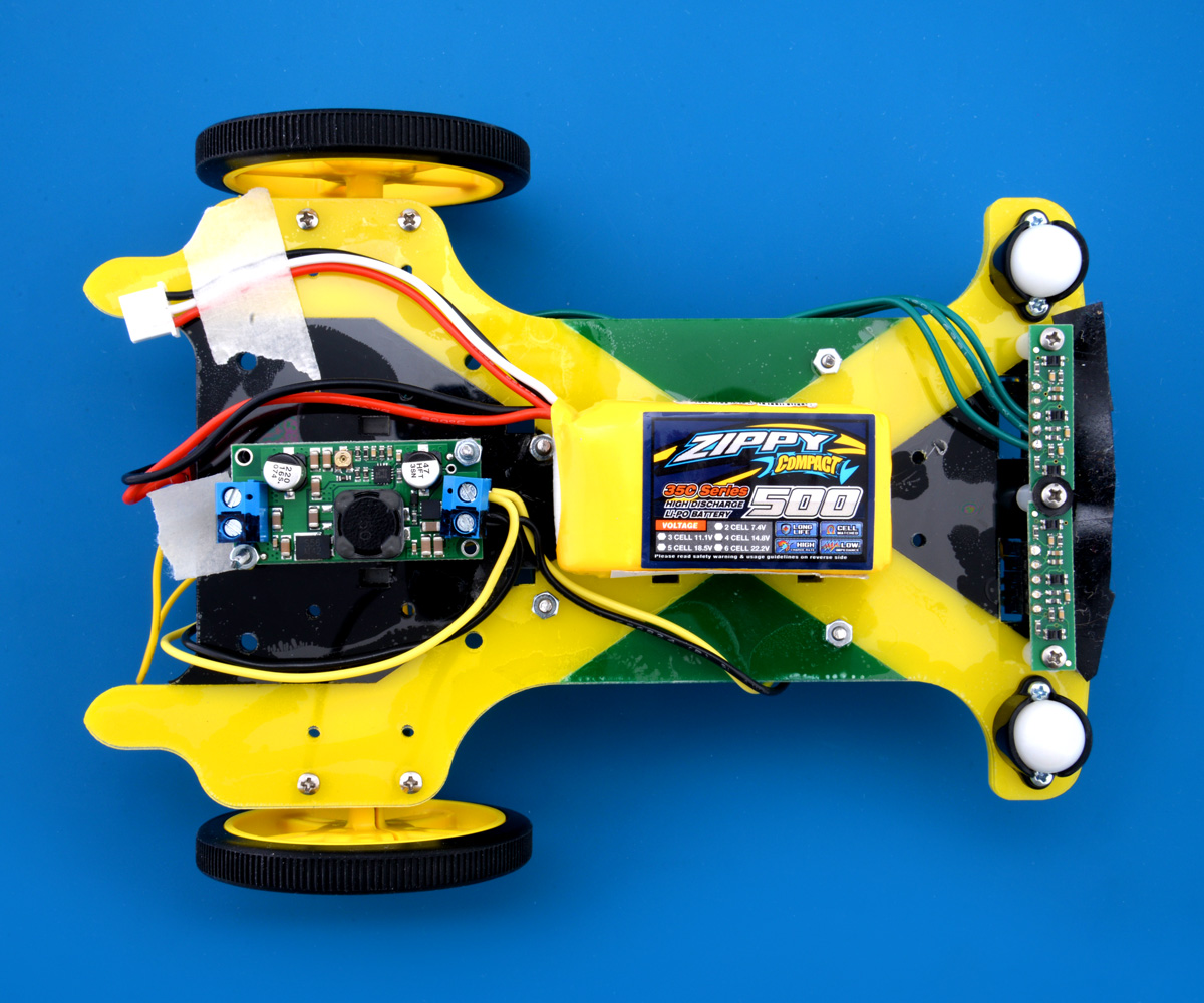
The name of my line follower is a throwback to Usain Volt, which was what I named my dead reckoning robot that didn’t reckon well, though it could follow a line. Usain Volt is, of course, a play on Usain Bolt, and the robot’s chassis and wiring has a color scheme and overall shape that is intended to resemble the bobsled of the Jamaican bobsleigh team. Fun fact: Usain Volt 2.0’s right wheel is one of the yellow 60mm wheels used on the original Usain Volt. (The original plan was to use both wheels, but one had formed a severe crack which eventually resulted in a catastrophic accident mid-turn during one of my line following test runs.)
Hardware
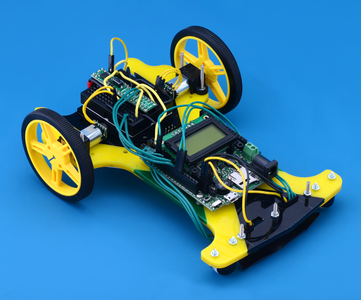
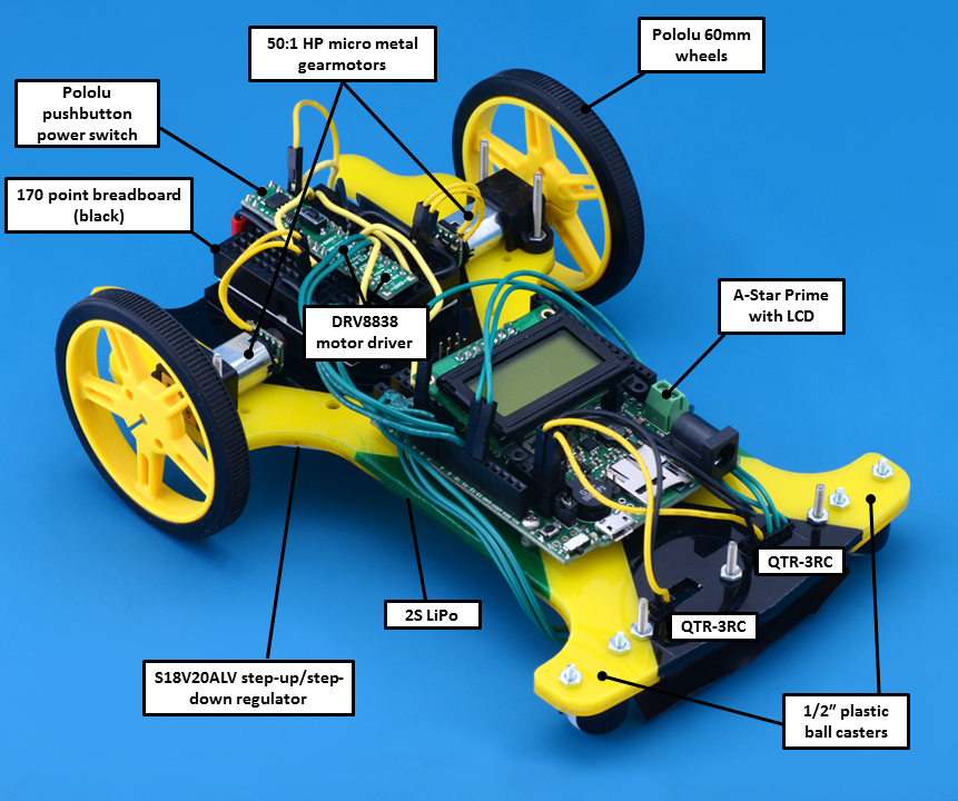
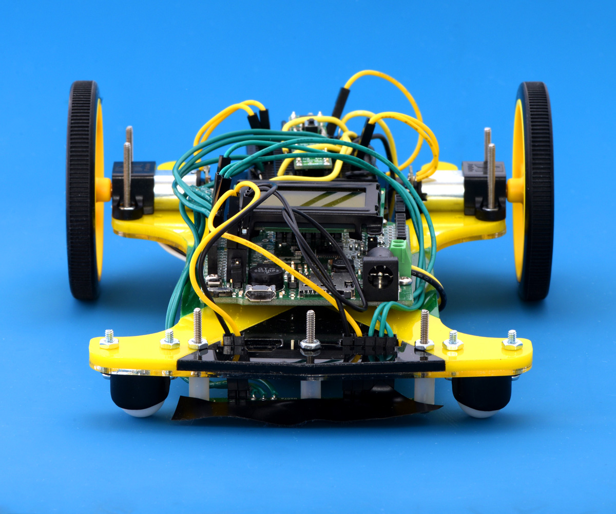
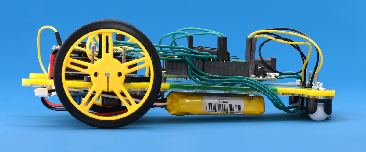
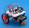
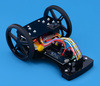
Like Mostly Red Racer, Usain Volt 2.0 is a two-wheeled differential drive robot. The drivetrain consists of two 50:1 HP gearmotors directly connected to a pair of 60mm Pololu wheels, and driven by two DRV8838 motor drivers (another fun fact: I routed that board!). Unlike Mostly Red Racer, Usain Volt 2.0 uses two 1/2″ plastic ball casters to support the chassis, intended partly to make the top view of the robot more resemble a bobsled, and partly to corner better. Two QTR-3RC sensors are used to detect the line, and a Pololu pushbutton power switch toggles power to an adjustable 4-12V buck/boost regulator and an A-Star Prime SV, which controls everything. The whole robot is powered by a low-profile 2S LiPo located on the underside of the chassis.
 |
|
|
|
 |
Construction
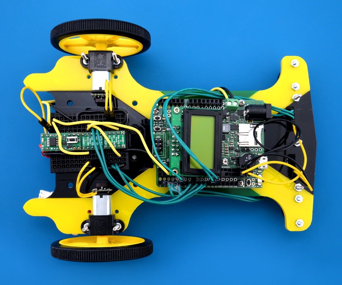
To mount all of my hardware, I made a chassis that was basically two layers of acrylic that were cut with Pololu’s laser cutting service. The top layer was made up of yellow, green, and black sections of 1/8″ acrylic that, when pieced together, would resemble the Jamaican flag. The bottom layer was a single piece of clear 1/16″ acrylic equal in size to the combined sections of the top layer, so that I could use acrylic glue to mate the two layers together. The bottom layer being clear allows people to see my color scheme when the robot is viewed from the bottom. However, a downside to the bottom layer being clear is that when the robot is held up to the light at certain angles, you can see exactly where the acrylic glue spread to bond the two layers together.
I used a black breadboard to hold the pushbutton power switch and motor drivers (the breadboard has an adhesive backing, which is convenient for mounting to flat surfaces), and a mix of premium jumper wires and solid core wires were used for the connections between the electronics. The A* Prime, regulator, and QTR sensors are mounted with #2-56 sized screws and nuts and offset with spacers so any soldered joints don’t just rest on the acrylic. The robot’s battery is held in place with double-sided tape.
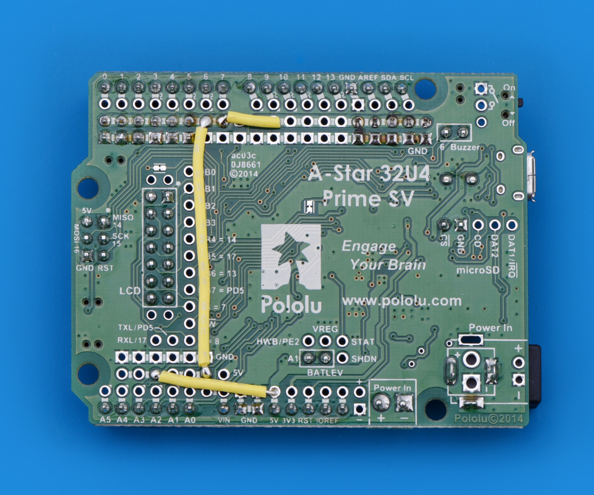
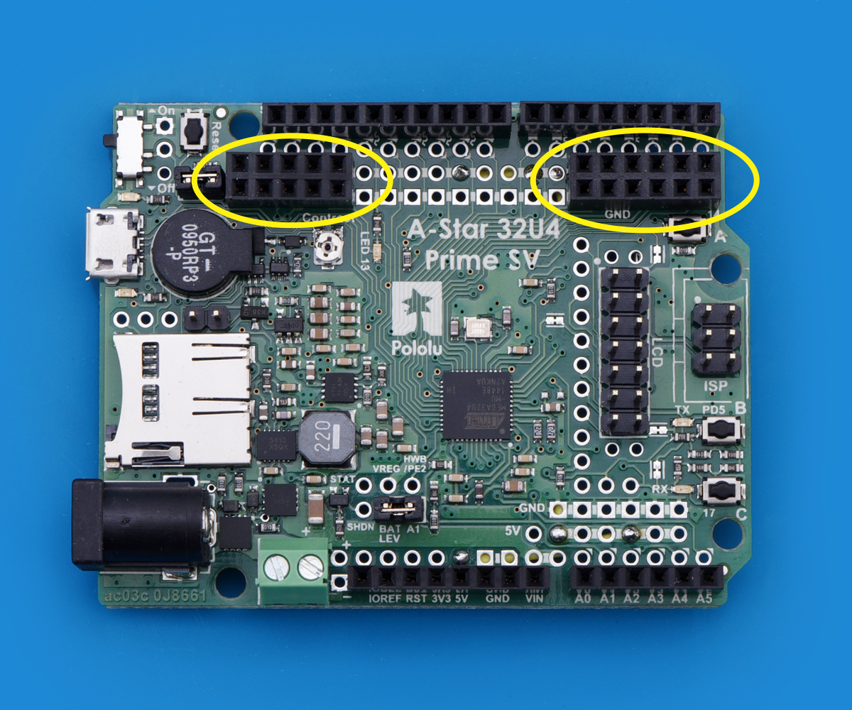
The A* Prime was especially fun and convenient to work with since it has many features useful for prototyping and making connections. In particular, I enjoyed using the additional ground and power access points (it has over 40 of each) to connect to my QTR sensors and motor drivers quickly with something simple like a solid core or premium jumper wire. Right next to the available ground rails on the Prime is a power rail that users can supply their own voltage to. Because the Prime’s 5V on-board switching regulator can provide up to 1.5A (plenty enough current for the logic power on both DRV8838s and both QTR sensor arrays, which draw current in bursts), I chose to solder some wires between the 5V pin and the power rails to permanently make that 5V available. I also added some female headers to make the power rail accessible to solid core wire. You can see my modifications in the pictures below:
|
|
Also, while programming, I found the A* Prime’s included pushbuttons and buzzer especially useful for various things like starting my QTR sensor calibration routine, knowing when the routine has finished, and starting the robot’s line following routine to begin a race. Although I did not use the LCD, I expect it to be a very useful debugging tool as I try to shave time off of Usain’s laps.
Future plans
I’m proud to have made a robot that can follow lines faster than an unmodified 3pi (it averaged 1.07 m/s during its best race)! It looks like my method of selecting hardware worked just fine, and I can now concentrate on improving the code. Right now, my sketch is a straightforward PID loop, and I want to incorporate some kind of speeding up during the straightaways, as well as tune the PID further to increase the overall base speed and reduce the overshoot on the turns. I suspect this is not the last time you’ll see Usain Volt 2.0; I included a set of mounting holes to add a second layer above the breadboard, which I could use to mount another, more powerful processor, and the micro metal gearmotors I am using have an extended motor shaft, which allows me to add magnetic encoders. Both of those features are key to reusing the robot for something like the 2014 dead reckoning competition.
Related products


-
David's line following robot that learns the course
- 1 May 2015Several people here made robots to compete in the recent LVBots line following competition. The goal of the competition is to make an autonomous...
-
Brandon's line following robot: The Chariot
- 6 May 2015For the recent LVBots line following competition, my first instinct was to try to come up with some unique alternative design for a robot that would...
15 comments

Ted

I did not have trouble uploading to the A-Star 32U4 Prime while working on my robot. However, in general, sometimes if the serial monitor window is left open while unplugging and replugging the A-Star, there can be problems. Those problems can be fixed by unplugging USB, closing all programs that might be using the serial port, and trying again. If you want help troubleshooting your particular problem, you can ask for help on our forum.
-Jon
The forums were helpful. It turned out that plugging into a different USB port on my computer fixes the problem. Strange that one port works and the other sometimes works. It might be that the port that worked has the regular USB label and the problem port is labeled SS-USB ).
Ted

Sure, I can share those files with you; I'll make them accessible via Thingiverse. However, this is my first time uploading and publishing a creation on Thingiverse, and they require a minimum wait time of 24 hours between account creation and publishing your first creation. For now, I was able to prepare and save a web page that they will be available at, so when it is published (by about this time tomorrow), I expect that you should be able to use this link to access those files.
As for your laser-cutting question, I am not sure about the least expensive way to get those pieces cut, but you could use our laser-cutting service (and you can ask them specific questions about laser-cutting, too.).
-Jon
Wanted to thank you for making your files available. We have built our first car for something other than line following and had a great time doing it. It was a huge help to have your thoughts on building your car, the list of parts, and the template. We really appreciate it!
I am glad my write-up was useful! We would love to hear about your car when it is finished, especially if you are using some of our products. For that, you might consider replying here or starting a new thread on the Share Your Projects part of our forum.
-Jon

I see you posted your chassis in Thingsverse (http://www.thingiverse.com/thing:1187952). I wanted to know if you happen to have a 3D compatible file for 3D printing. You listed dxf and cdr files that aren't compatible and therefore unprintable.
I'm very interested in this chassis and I've been trying to convert or modify the files you posted but I have been unsuccessful.
I would appreciate it if you could share with us some .stl file for 3D printing or something like that.
Thank you very much.
-MelZero.
I noticed you made a comment on my Thingiverse web page asking a similar question. I posted a reply there, which is a more appropriate site to talk about this.
-Jon

I do not have a wiring diagram for my robot. However, we describe the connections for our electronics on their product pages, which should make it easier to understand how to make your own connections. If you have questions about how to use any of our products, you can always email us or post to our forum.
As for code, I do not think it is useful to upload mine seeing as how its entirely based on and not much different than our 3pi's PID line following code, which you can find inside the 3pi's user's guide.
Also, I wrote my code in the Arduino IDE, which uses a language based on C/C++ (not Python).
-Jon

-Jon

I've tried the simplified PID from online tutorials and I'm going to try the PID algorithm from 3pi. Tell me, please, what are the differences between the code from 3pi and this robot? Only in changing the coefficients?

Brandon
Post a comment


Home | Forum | Blog | Support | Ordering Information | Lists | Distributors | BIG Order Form | About | Contact
© 2001–2025 Pololu Corporation
