Development Boards (Programmable Controllers) » Arduino-Compatible » Shields for Arduino »
Pololu Dual VNH5019 Motor Driver Shield for Arduino

Get your Arduino moving! This shield makes it easy to control two high-power DC motors with your Arduino or Arduino-compatible board. Its dual robust VNH5019 motor drivers operate from 5.5 to 24 V and can deliver a continuous 12 A (30 A peak) per motor, or a continuous 24 A (60 A peak) to a single motor connected to both channels. These great drivers also offer current-sense feedback and accept ultrasonic PWM frequencies for quieter operation. The Arduino pin mappings can all be customized if the defaults are not convenient, and the motor driver control lines are broken out along the left side of the shield for general-purpose use without an Arduino.
 Compare all products in Shields for Arduino or Brushed DC Motor Drivers.
| Description | Specs (13) | Pictures (6) | Resources (9) | FAQs (0) | On the blog (2) | Distributors (49) |
|---|
Overview
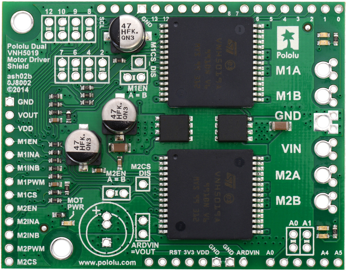 |
Pololu dual VNH5019 motor driver shield for Arduino. |
|---|
This motor driver shield and its corresponding Arduino library make it easy to control two bidirectional, high-power, brushed DC motors with an Arduino or compatible board, such as the A-Star 32U4 Prime. The board features a pair of robust VNH5019 motor drivers from ST, which operate from 5.5 to 24 V and can deliver a continuous 12 A (30 A peak) per channel, and incorporates most of the components of the typical application diagram on page 14 of the VNH5019 datasheet (1MB pdf), including pull-up and protection resistors and FETs for reverse battery protection. It ships fully populated with its SMD components, including the two VNH5019 ICs, as shown in the picture to the right; stackable Arduino headers and terminal blocks for connecting motors and motor power are included but are not soldered in (see the Included Hardware section below).
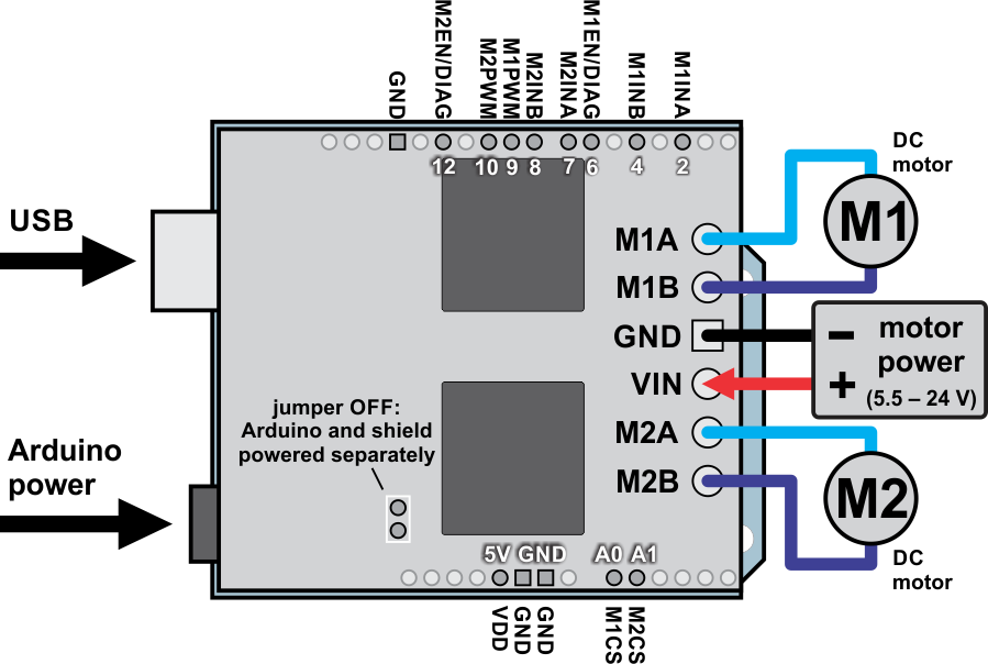
This versatile motor driver is intended for a wide range of users, from beginners who just want a plug-and-play motor control solution for their Arduinos (and are okay with a little soldering) to experts who want to directly interface with ST’s great motor driver ICs. The Arduino pin mappings can all be customized if the defaults are not convenient, and the VNH5019 control lines are broken out along the left side of the board for general-purpose use without an Arduino (see the right connection diagram below). This versatility, along with an option to power the Arduino directly from the shield, sets this board apart from similar competing motor shields.
|
|

For a lower-power, lower-cost alternative to this shield, please consider the Dual MC33926 Motor Driver Shield, which has a very similar design and can deliver a continuous 3 A per channel.
For high-power motor driver shields that operate to higher voltages and can deliver more current, see the newer Dual G2 High-Power Motor Driver Shields.
Features
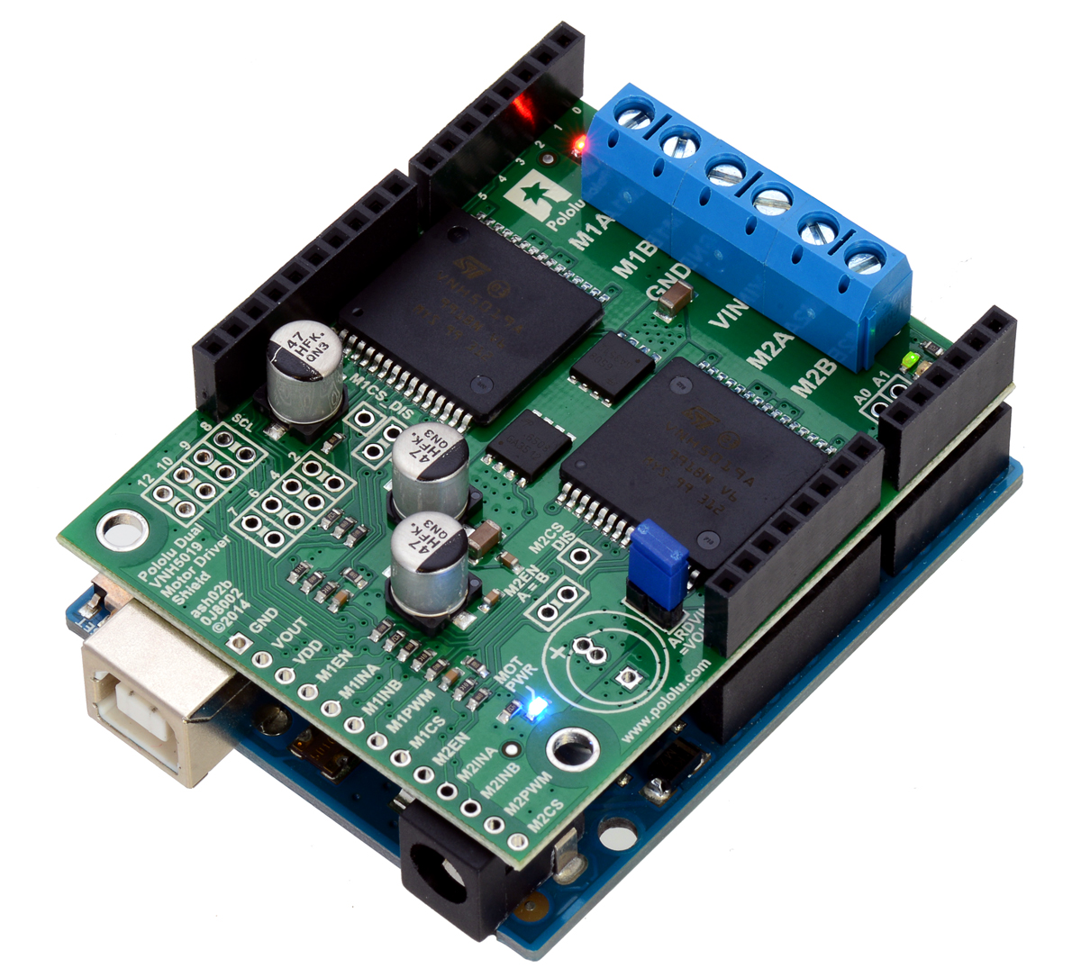 |
Pololu dual VNH5019 motor driver shield, assembled and connected to an Arduino Uno R3. |
|---|
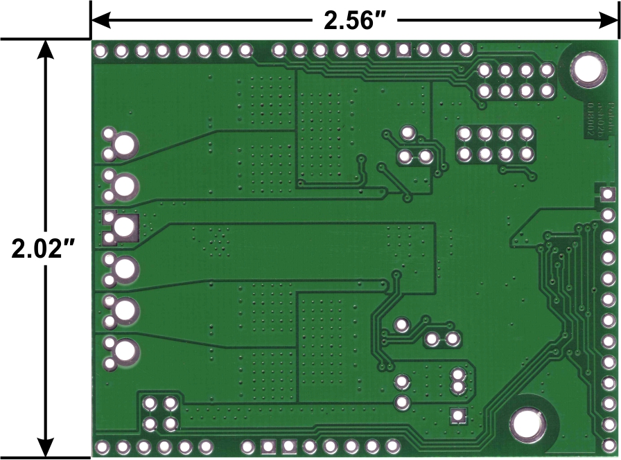 |
Pololu dual VNH5019 motor driver shield for Arduino, bottom view with board dimensions. |
|---|
- Wide operating voltage range: 5.5 – 24 V1
- High output current: up to 12 A continuous (30 maximum) per motor
- Motor outputs can be combined to deliver up to 24 A continuous (60 A maximum) to a single motor
- Inputs compatible with both 5V and 3.3V systems (logic high threshold is 2.1 V)
- PWM operation up to 20 kHz, which is ultrasonic and allows for quieter motor operation
- Current sense voltage output proportional to motor current (approx. 140 mV/A; only active while H-bridge is driving)
- Motor indicator LEDs show what the outputs are doing even when no motor is connected
- Can be used with an Arduino or Arduino clone (through shield headers) or other microcontroller boards (through 0.1″ header along the left side)
- When used as a shield, the motor power supply can optionally be used to power the Arduino base as well
- Arduino pin mappings can be customized if the default mappings are not convenient
- Arduino library makes it easy to get started using this board as a motor driver shield
- Detailed user’s guide
- Reverse-voltage protection to -16 V
- Robust drivers:
- Can survive input voltages up to 41 V
- Undervoltage and overvoltage shutdown
- High-side and low-side thermal shutdown
- Short-to-ground and short-to-Vcc protection
1 While the overvoltage protection typically kicks in at 27 V, it can trigger at voltages as low as 24 V, so we do not recommend using this motor driver with 24 V batteries, which significantly exceed 24 V when fully charged. If the shield is configured to power an Arduino or Arduino clone, the supply voltage must conform to that Arduino’s input voltage requirements.
Included Hardware
 |
Pololu dual VNH5019 motor driver shield for Arduino with included hardware. |
|---|
This motor driver board ships with all of the surface-mount parts populated. However, soldering is required for assembly of the included through-hole parts. The following through-hole parts are included:
- one extended/stackable 1×10 female header (for Arduino shields)
- two extended/stackable 1×8 female headers (for Arduino shields)
- two extended/stackable 1×6 female headers (for Arduino shields)
- three 2-pin 5mm terminal blocks (for board power and motor outputs)
- 40-pin 0.1″ straight breakaway male header (may ship in several pieces, such as two 20-pin strips)
A 0.1″ shorting block (for optionally supplying shield power to Arduino) is also included.
You can solder the terminal blocks to the six large through-holes to make your motor and motor power connections, or you can break off a 12×1 section of the 0.1″ header strip and solder it into the smaller through-holes that border these larger holes. Note, however, that the terminal blocks are only rated for 16 A, and each header pin pair is only rated for a combined 6 A, so for higher-power applications, thick wires should be soldered directly to the board.
When not using this board as an Arduino shield, you can solder the 0.1″ headers to the logic connections along the left side of the board to enable use with custom cables or solderless breadboards, or you can solder wires directly to the board for more compact installations. Note that motor and motor power connections should not be made through a breadboard.
The motor driver includes three 47 uF electrolytic power capacitors, and there is room to add additional capacitors (e.g. to compensate for long power wires or increase stability of the power supply). Additional power capacitors are usually not necessary, and no additional capacitors are included with this motor driver.
The two mounting holes are intended for use with #4 screws (not included). They have a horizontal separation of 0.30″ and a vertical separation of 1.70″.
An Arduino is not included.
Schematic Diagram
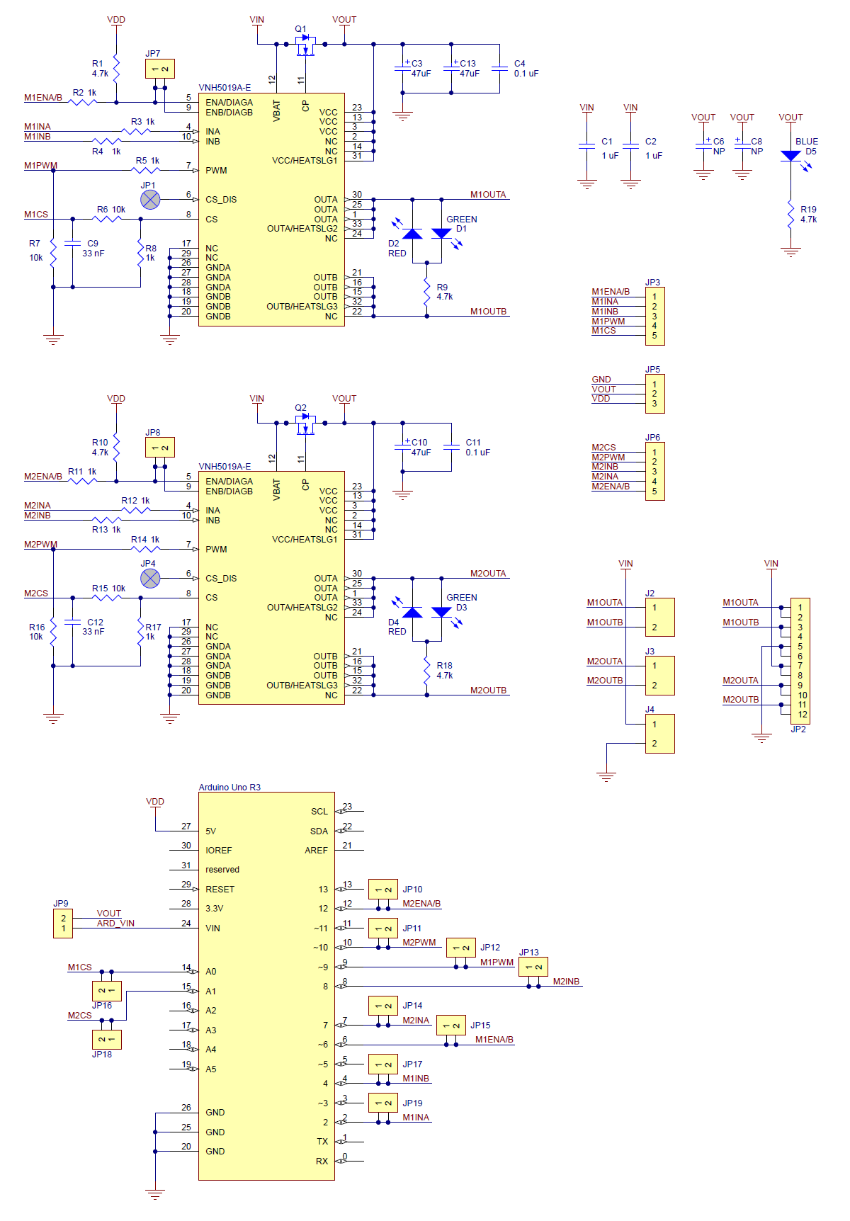 |
Schematic diagram of the Pololu dual VNH5019 motor driver shield for Arduino. |
|---|
This schematic is also available as a downloadable pdf: dual VNH5019 motor driver shield schematic (356k pdf)
VNH3SP30, VNH2SP30, and VNH5019 Comparison
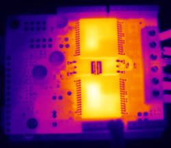 |
Thermal image of the top side of the dual VNH5019 motor driver shield during one of our current tests. |
|---|
In addition to this VNH5019 shield, we offer carrier boards for two similar, older motor drivers from ST: the VNH3SP30 and the VNH2SP30. The VNH5019 is the only one of the three with a practical operating voltage above 16 V. The VNH5019 is the only driver of the three available on a Pololu Arduino shield.
The current-related values in the table below (i.e. the entries to which footnote 3 applies) are the results of tests on only one or two of each driver version, so they do not capture potential unit-to-unit variation, and they were performed using the single driver versions, not the dual carriers. As such, the values should be treated as rough estimates of performance, not as performance guarantees. While these tests seem to indicate that the VNH2SP30 runs a bit cooler—and hence can deliver more continuous current—than the VNH5019, it is important to note that the three driver versions were tested at different times under potentially different conditions, so the results are not necessarily accurate indications of relative performance.
In our tests, we noticed that the thermal protection on the VNH5019 was activating at a lower temperature (153°C) than on the VNH2SP30 (170°C), which could partially account for the shorter VNH5019 overheating times. However, we also observed that the VNH5019 was reaching slightly higher temperatures than the VNH2SP30 when used under the same conditions: the VNH5019 reached a temperature of 85°C after 3 minutes at 10 A while the VNH2SP30 reached a temperature of 80°C.
The following table offers a comparison of the single-carrier versions of all three drivers:
| VNH3SP30 | VNH2SP30 | VNH5019 | |
|---|---|---|---|
| Operating voltage: (1) | 5.5 – 16 V (2) | 5.5 – 16 V | 5.5 – 24 V |
| MOSFET on-resistance (per leg): | 34 mΩ typ. | 19 mΩ max. | 18 mΩ typ. |
| Max PWM frequency | 10 kHz | 20 kHz | 20 kHz |
| Current sense | n/a | 0.13 V/A typ. | 0.14 V/A typ. |
| Over-voltage shutoff | 36 V min. (2) / 43 V typ. | 16 V min. / 19 V typ. | 24 V min. / 27 V typ. |
| Logic input high threshold | 3.25 V min. | 3.25 V min. | 2.1 V min. |
| Time to overheat at 20 A (3) | 8 s | 35 s | 20 s |
| Time to overheat at 15 A (3) | 30 s | 150 s | 90 s |
| Current for infinite run time (3) | 9 A | 14 A | 12 A |
1 The VNH3SP30 can survive input voltages up to 40 V, and the VNH2SP30 and VNH5019 can survive input voltages up to 41 V, but the over-voltage shutoff will kick in at lower voltages.
2 While VNH3SP30’s over-voltage shutoff doesn’t activate until 36 V, in our experience, shoot-through currents make PWM operation impractical above 16 V.
3 Typical results using the Pololu motor driver carrier boards with 100% duty cycle at room temperature (with no forced airflow or heat sinking beyond the carrier PCB).
Real-world power dissipation consideration
Each motor driver IC has a maximum continuous current rating of 30 A. However, the chips by themselves will overheat at lower currents (see the table above for typical values). The actual current you can deliver will depend on how well you can keep the motor drivers cool. The shield’s printed circuit board is designed to draw heat out of the motor driver chips, but performance can be improved by adding heat sinks. In our tests, we were able to deliver short durations (on the order of milliseconds) of 30 A and several seconds of 20 A without overheating. At 6 A, the chip gets just barely noticeably warm to the touch. For high-current installations, the motor and power supply wires should also be soldered directly instead of going through the supplied terminal blocks, which are rated for up to 16 A.
This product can get hot enough to burn you long before the chip overheats. Take care when handling this product and other components connected to it.
Many motor controllers or speed controllers can have peak current ratings that are substantially higher than the continuous current rating; this is not the case with these motor drivers, which have a 30 A continuous rating and over-current protection that can kick in as low as 30 A (50 A typical). Therefore, the stall current of your motor should not be more than 30 A. (Even if you expect to run at a much lower average current, the motor can still draw short bursts of high currents, such as when it is starting, if special steps are not taken.)
Current sense outputs
The voltages on the M1CS and M2CS pins are each approximately equal to 140 mV per amp of output current of the corresponding motor. The current sense readings are more accurate at higher currents. Note that the output is only active while the H-bridge is driving; it is inactive (low) when the driver is coasting (motor outputs are high impedance) or braking. During the coast portion of the drive/coast cycle, current will continue to circulate through the motor, but the voltage on the FB pin will not accurately reflect the motor current.
The current sense output pins are designed for PWM frequencies of 5 kHz or higher. If you use a PWM frequency lower than 5 kHz and want to measure the current, we recommend adding an extra capacitor between the current sense output pin and GND to smooth out the signal. For example, if you use a PWM frequency of 490 Hz and want to measure the current of M1, you should add a 1 µF capacitor (or larger) between M1CS and GND.
Note that while the M1CS and M2CS voltages can potentially exceed 3.3 V at high currents, the current sense circuit should be safe for use with many 3.3V analog inputs. Most MCUs have integrated protection diodes that will clamp the input voltage to a safe value, and since the CS circuit has a 10 kΩ resistor in series with the output, only a few hundred microamps at most will flow through that diode.
Note: The datasheet refers to the motor driver IC by the full part number VNH5019A-E, but the “A” seems to simply indicate that it was packaged in tubes. It mentions VNH5019TR-E as another valid part number for this IC (indicating tape-and-reel packaging).
This newer version (ash02b) of our dual VNH5019 motor driver shield replaces the original version. The new version adds pass-throughs for the four new pins on the Arduino Uno R3. Generally speaking, most users should not notice any other differences between the two shield versions; details can be found in this section of the user’s guide. The easiest way to distinguish between the two versions is via the silkscreen in the top left corner, where the new version is labeled ash02b and the original version is labeled ash02a.
Related products


Home | Forum | Blog | Support | Ordering Information | Lists | Distributors | BIG Order Form | About | Contact
© 2001–2026 Pololu Corporation
