Encoder for Pololu Wheel 42x19mm

This quadrature encoder works with our micro metal gearmotors, 42×19mm wheel, and extended bracket to measure the rotation speed and direction of the wheel. With twelve teeth on the wheel, the system provides a resolution of 48 counts per revolution, which corresponds to a linear resolution of just under 3 mm or 1/8″
| Description | Specs (0) | Pictures (8) | Resources (3) | FAQs (0) | On the blog (1) | Distributors (0) |
|---|
Discontinuation notice: We have released a newer encoder solution for our micro metal gearmotors that provides many more counts per revolution and does not put any restrictions on the gearbox output shaft. This older encoder is now only available by large-volume special order; please contact us for more information.
Overview
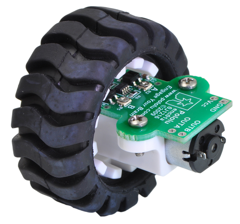 |
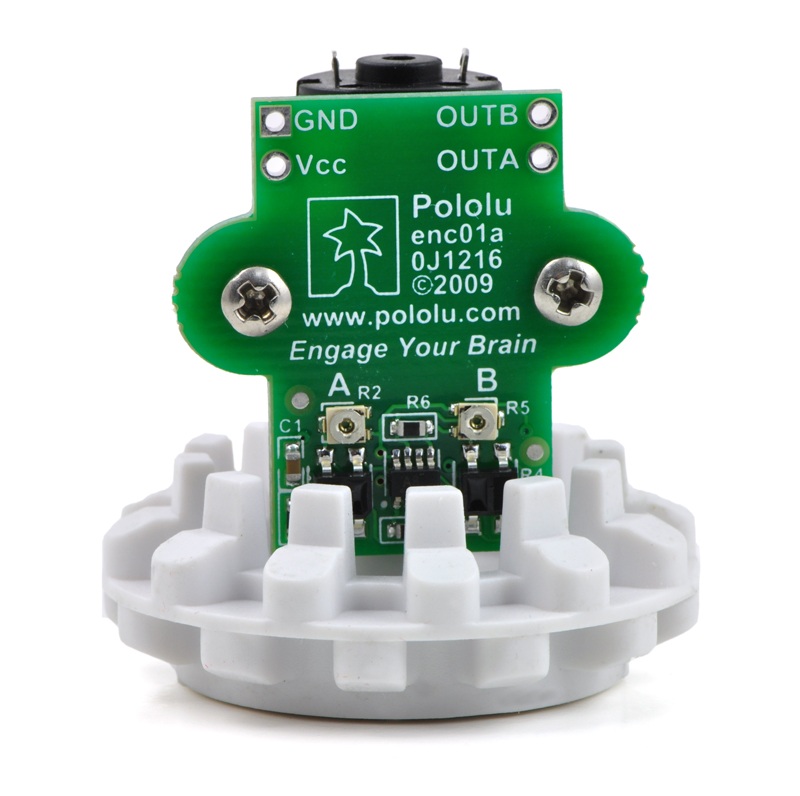
This quadrature encoder board is designed to work with Pololu micro metal gearmotors by holding two infrared reflectance sensors inside the hub of a Pololu 42×19mm wheel and measuring the movement of the twelve teeth along the wheel’s rim. The two sensors are spaced to provide waveforms approximately 90 degrees out of phase, allowing the direction of rotation to be determined and providing four counts per tooth for a resolution of 48 counts per wheel rotation. Each analog sensor signal is fed to a comparator with hysteresis to provide glitch-free digital outputs. The compact layout of the board fits all of the components within the envelope of the hub and tire, allowing the board to be mounted between the motor and a chassis. The encoder is calibrated for operation from 4.5 V to 5.5 V, but it can be recalibrated for operation at 3.3 V.
Example code for the encoders is provided with the Pololu AVR Library. The example shows how the encoders can be used with AVR-based robot controllers, including the Orangutan Robot Controllers and the Arduino platform.
Note that this encoder will only work with the Pololu 42×19mm wheel. If you are looking for a higher-resolution quadrature encoder that works with micro metal gearmotors and arbitrary wheels, consider the magnetic encoder pair kit for micro metal gearmotors. We also have versions of our larger 25D mm and 37D mm metal gearmotors with integrated quadrature encoders.
Note: This encoder is designed to work with our 5:1 to 298:1 micro metal gearmotors. Motors are not included and must be purchased separately. This encoder will not work with the 1000:1 gear ratio version of our micro metal gearmotors due to the longer gearbox.
Feature summary
- operating voltage: 4.5 V to 5.5 V (encoder can be modified for lower voltages)
- two digital outputs (quadrature)
- 14 mA current consumption at 5.0 V
- 48 counts per revolution (linear resolution of just under 3 mm or 1/8")
- small size: fits between motor and chassis.
- weight: 1.6 g (0.06 oz)
Using the Encoder
The encoder is designed to fit within the outline of the extended micro gearmotor brackets that are in turn designed to work with the Pololu 42×19mm wheel and Pololu micro metal gearmotors, so most applications that can use that bracket should require little or no modifications, though it should be noted that the 1/16" thickness of the PCB will change the height of a chassis relative to the wheel. For convenience, we offer an encoder set that includes two encoders, a pair of 42×19mm wheels, and a pair of extended brackets; the micro metal gearmotors are sold separately. These encoders are only compatible with the 42×19mm wheel, extended micro gearmotor bracket, and 5:1 to 298:1 versions of the micro metal gearmotors.
|
|
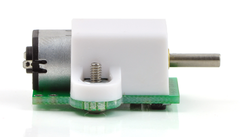
The power and output connections are brought out to the end of the PCB under the motor terminals so that wiring to all six terminals can be routed together. Wires can be soldered directly to the through-hole power and output pads, or some connectors with a 0.1" spacing, such as our 0.1" female header or 0.1" male header strip, can also be used.
The two outputs of the encoder are digital outputs that can be connected directly to digital input pins on most microcontrollers (inputs that can generate interrupts on change are recommended). With 48 state changes per revolution of the 42 mm wheel, a speed of 1 m/s (a bit over 3 feet per second) generates approximately 360 state changes per second. With two encoders used simultaneously, as is the case for most differential-drive robots, the encoders will require attention almost every millisecond. Decoding the encoder outputs should only take a few percent of the processing power of a high-performance microcontroller such as the Atmel AVR used in the Pololu Orangutan robot controllers, but the encoders might be difficult to use with slower microcontrollers without available external interrupts.
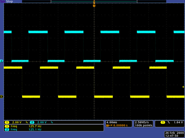 |
Oscilloscope capture of encoder outputs with the wheel spinning at 630 RPM. |
|---|
Modifying the Encoder for 3.3 V Operation
 |
The encoder is calibrated for 5.0 V operation, but it can be modified for operation at 3.3 V. The modification consists of two steps: reducing the IR emitter current-limiting resistance, and calibrating for the two phototransistor sensors (a simplified schematic diagram of the encoder is shown below). The IR emitter current-limiting resistance for the two emitters, which are in series, is implemented by R1 and R4; bypassing R4 with a short halves the resistance from power to the LEDs. R4 is labeled on the circuit board silkscreen; one simple way to bypass it is to solder a thin solid wire (such as the lead of a 1/4-watt resistor) to both sides of the resistor and then to clip off the excess wire. With the resistor bypassed and the circuit powered at 3.3 V, the encoder will draw approximately 10 mA.
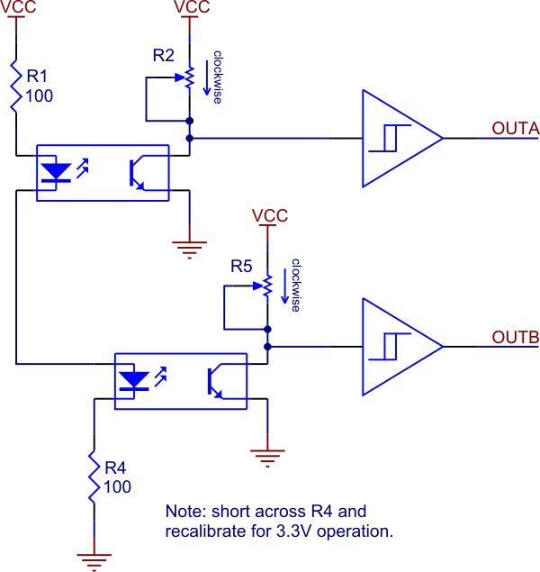 |
Schematic diagram of the encoder for the Pololu wheel 42×19mm. |
|---|
Next, the encoder must be calibrated (to compensate for the dimmer IR LEDs). Each channel has a separate trimmer potentiometer that can be adjusted such that at a constant wheel speed, the output of the channel is a square wave with 50% duty cycle. This is easiest with an oscilloscope connected to the outputs, but it can also be done with a microcontroller programmed to measure the duty cycle of the outputs. If the duty cycle is too high (or there are no low pulses at all), the potentiometer should be turned clockwise; if the duty cycle is too low, the potentiometer should be turned counter-clockwise.
Note: The trimmer potentiometer is very small, and it can be damaged by using a screwdriver that is not the correct size.
Related products


Home | Forum | Blog | Support | Ordering Information | Lists | Distributors | BIG Order Form | About | Contact
© 2001–2026 Pololu Corporation
