Support »
Jrk G2 Motor Controller User’s Guide
View document on multiple pages.
You can also view this document as a printable PDF.
- 1. Overview
- 2. Contacting Pololu
- 3. Getting started
- 4. Basic setup
- 5. Setting up the feedback method
- 6. Setting up the control method
- 7. Details
- 8. Pinout and components
- 9. Setting reference
- 10. Variable reference
- 11. Command reference
- 12. Serial command encoding
- 13. I²C command encoding
- 14. USB command encoding
- 15. Writing PC software to control the Jrk
- 15.1. Example code to run jrk2cmd in C
- 15.2. Example code to run jrk2cmd in Ruby
- 15.3. Example code to run jrk2cmd in Python
- 15.4. Running jrk2cmd with Windows shortcuts
- 15.5. Example serial code for Linux and macOS in C
- 15.6. Example serial code for Windows in C
- 15.7. Example serial code in Python
- 15.8. Example I²C code for Linux in C
- 15.9. Example I²C code for Linux in Python
- 15.10. Example I²C code for MicroPython
1. Overview
The second-generation Jrk G2 motor controllers are designed to enable easy closed-loop speed control or position control (but not both!) of a single brushed DC motor. They feature integrated support for analog voltage or tachometer (frequency) feedback and a variety of control interfaces–USB for direct connection to a computer, TTL serial and I²C for use with a microcontroller, RC hobby servo pulses for use in an RC system, and analog voltages for use with a potentiometer or analog joystick. A free configuration utility simplifies initial setup of the device, provides access to a wide array of configurable settings, and allows for in-system testing and monitoring of the controller via USB.
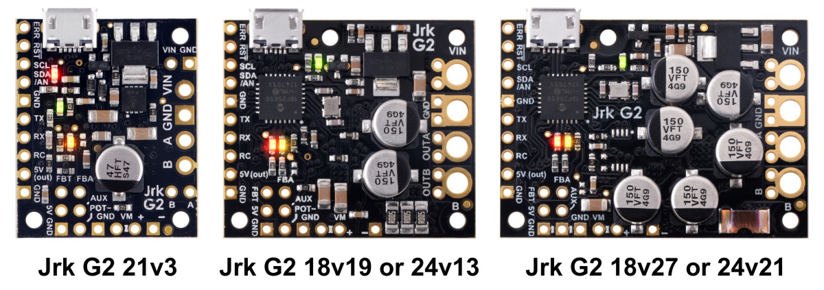 |
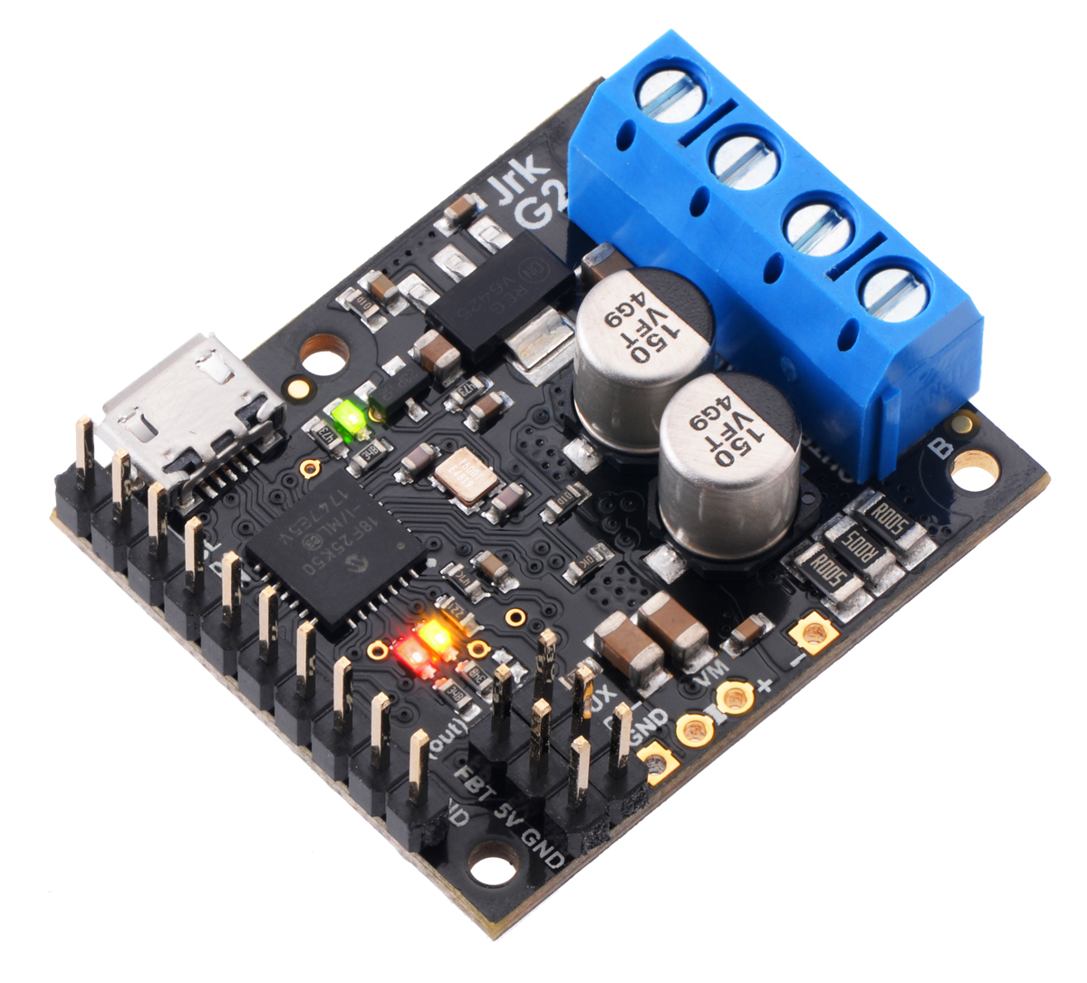
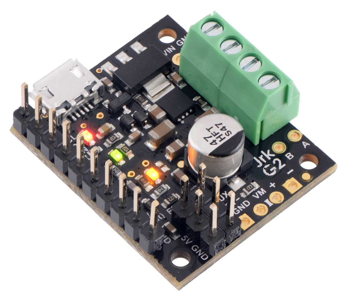
Side-by-side comparison of the different Jrk G2 USB Motor Controllers with Feedback. |
|---|
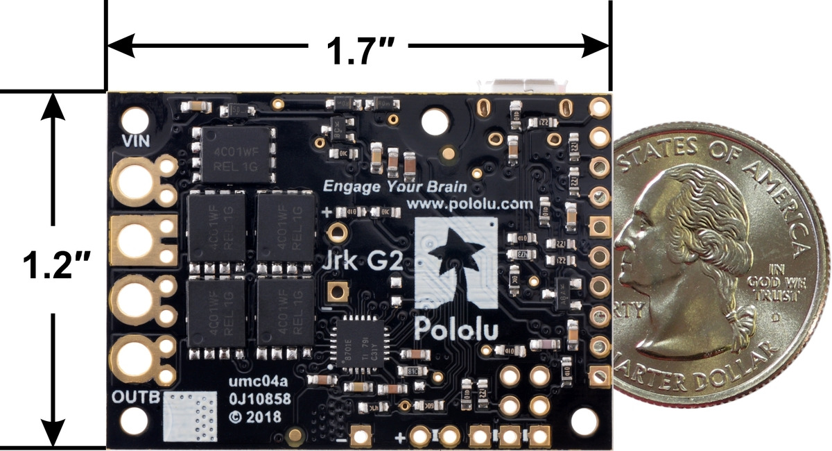
The table below lists the members of the Jrk G2 family and shows the key differences among them.
 Jrk G2 21v3 |
 Jrk G2 18v19 |
 Jrk G2 24v13 |
 Jrk G2 18v27 |
 Jrk G2 24v21 |
|
|---|---|---|---|---|---|
| Minimum operating voltage: |
4.5 V(1) | 6.5 V | 6.5 V | 6.5 V | 6.5 V |
| Recommended max operating voltage: |
28 V(2) | 24 V(3) | 34 V(4) | 24 V(3) | 34 V(4) |
| Max nominal battery voltage: |
24 V | 18 V | 28 V | 18 V | 28 V |
| Max continuous current (no additional cooling): |
2.6 A | 19 A | 13 A | 27 A | 21 A |
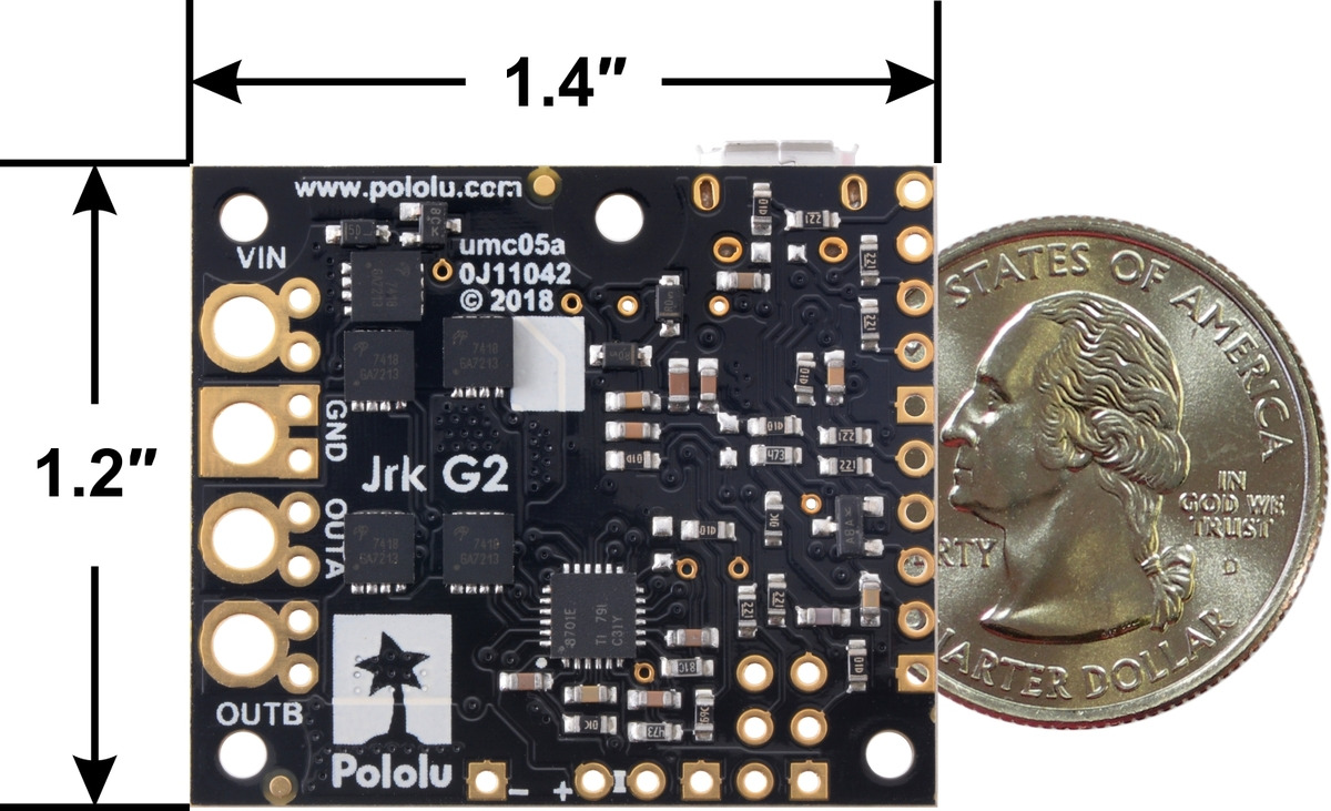
| Dimensions: | 1.0″ × 1.2″ | 1.4″ × 1.2″ | 1.7″ × 1.2″ | ||
1 The 5V logic voltage drops when powered from a supply below about 5.2 V.
2 Transient operation (< 500 ms) up to 40 V.
3 30 V absolute max.
4 40 V absolute max.
Features and specifications
- Easy open-loop or closed-loop control of one brushed DC motor
- A variety of control interfaces:
- USB for direct connection to a computer
- TTL serial operating at 5 V for use with a microcontroller
- I²C for use with a microcontroller
- RC hobby servo pulses for use in an RC system
- Analog voltage for use with a potentiometer or analog joystick
- Feedback options:
- Analog voltage (0 V to 5 V), for making a closed-loop servo system
- Frequency, for closed-loop speed control using pulse counting (for higher-frequency feedback) or pulse timing (for lower-frequency feedback)
- None, for open-loop speed control
- Note: the Jrk does not support using quadrature encoders for position control
- Ultrasonic 20 kHz PWM for quieter operation (can be configured to use 5 kHz instead)
- Simple configuration and calibration over USB with free configuration software utility (for Windows, Linux, and macOS)
- Configurable parameters include:
- PID period and PID coefficients (feedback tuning parameters)
- Maximum current
- Maximum duty cycle
- Maximum acceleration and deceleration
- Error response
- Input calibration (learning) for analog and RC control
- Optional CRC error detection eliminates communication errors caused by noise or software faults
- Reversed-power protection
- Field-upgradeable firmware
- Optional feedback potentiometer disconnect detection
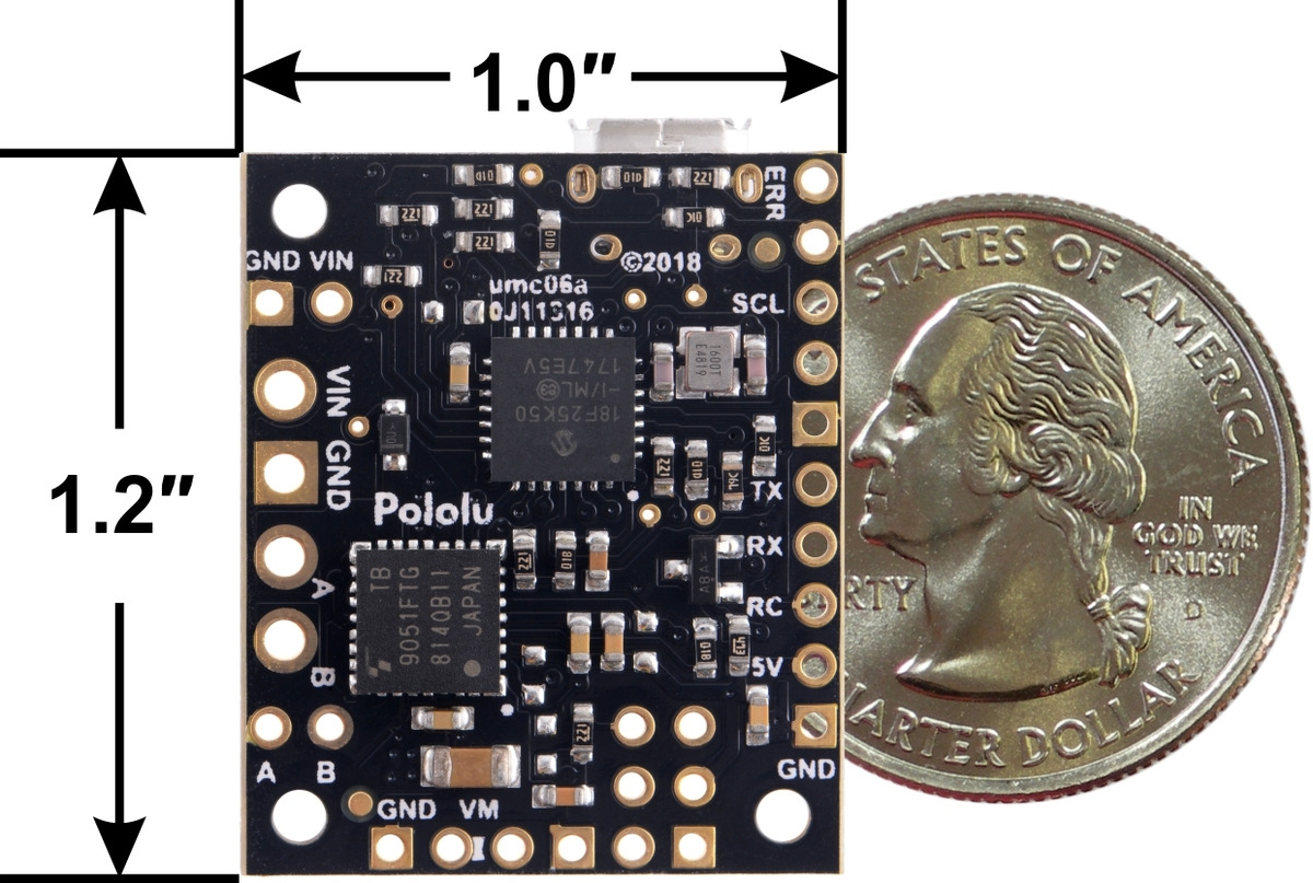 |
Jrk G2 21v3 USB Motor Controller with Feedback, bottom view with dimensions. |
|---|
|
|
Note: This guide only applies to the Jrk G2 motor controllers, which have black circuit boards. If you have one of the first-generation Jrk 21v3 or Jrk 12v12 controllers, which have green circuit boards, you can find their user’s guide here.
1.1. Supported operating systems
We support using the Jrk G2 and its configuration software on Windows 7, Windows 8, Windows 10, Windows 11, Linux, and macOS 10.11 or later. The Jrk G2 software is not likely to work on Windows 10 IoT Core, which is very different from the normal desktop versions of Windows. The software is open source, so it could be ported to more platforms.
1.2. Comparison to the original Jrk controllers
This section lists most of the things you should consider if you have an existing application using the original Jrk 21v3 or Jrk 12v12 controllers and are considering upgrading to a Jrk G2.
Motor driver improvements
Compared to the original Jrk controllers, the discrete MOSFET H-bridges on the Jrk G2 18v19, 24v13, 18v27, and 24v21 support higher operating voltages and larger output currents. Additionally, those Jrk G2 models have configurable hardware current limiting: when the motor current exceeds a configurable threshold, the motor driver uses current chopping to actively limit it.
The Jrk G2 21v3 uses a TB9051FTG motor driver that features hardware current chopping with a fixed threshold of approximately 6.5 A.
Physical connection changes
You will need to keep some things in mind when updating the physical connections of an existing application:
- The Jrk G2 circuit boards have different dimensions, mounting hole locations, and pin locations.
- On the Jrk G2, the RC pulse input should be connected to the pin named RC instead of RX.
- On the Jrk G2, analog control inputs should be connected to SDA/AN instead of RX.
- An analog control potentiometer should generally be powered from SCL and GND if you want to detect disconnection (instead of AUX and GND).
- The Jrk G2 does not have a pin named FB: analog feedback signals should be connected to the FBA pin and frequency/tachometer feedback signals should be connected to the FBT pin.
- An analog feedback potentiometer should generally be powered from AUX and POT− (21v3, 18v19, and 24v13 only), or AUX and GND.
- Unlike the FB pin on the original jrks, the FBA pin does not have a pull-up resistor. If you need one, you can add it externally or connect FBA to FBT to take advantage of the FBT pull-up resistor.
- The Jrk G2 uses a USB Micro-B connector (the original Jrks used Mini-B).
Configuration and software changes
There are several changes to keep in mind when configuring the Jrk G2 or updating any software that communicates with it:
- The Jrk G2 uses different configuration software from the original Jrk controllers. It is open source and works on Windows, Linux, and macOS. See Section 3 for installation instructions.
- The Jrk G2 serial protocol is generally a superset of the original Jrk serial protocol, so in many cases, serial interface software running on a microcontroller or computer (using the Jrk’s RX and TX lines or its virtual USB serial ports) will not need to be modified to work with the Jrk G2.
- The Jrk G2 native USB interface uses different product IDs and supports a different set of USB commands. However, the “Set target” and “Motor off” commands are unchanged.
- The “detect baud rate” feature was removed, so you will need to configure the baud rate of your Jrk ahead of time using the Jrk G2 Configuration Utility if you are controlling it over serial with a microcontroller.
- The default “Feedback mode” on the Jrk G2 is “None” instead of “Analog”.
- On the Jrk G2, the analog control input pin (SDA/AN) does not have its pull-up resistor enabled by default, but there is an option to enable it in the “Pin configuration” tab of the Jrk G2 configuration utility. (The original Jrk always enabled a pull-up on RX, which served as the analog input.)
- The Jrk G2’s “Feedback deadzone” feature has been changed so that it applies to “Duty cycle target” instead of “Duty cycle”, which makes it compatible with the new deceleration limits.
- The Jrk G2’s “Duty cycle” variable will move towards zero (either immediately or limited by the configurable deceleration limit) when there is an error, so the Jrk G2 will respect acceleration limits properly once the error is resolved.
- The 8-bit “Current” variable (which can be fetched with the serial command 0x8F) has units of 256 mA on the Jrk G2. A new 16-bit current variable is available with higher resolution.
- Unlike the original Jrk controllers, the Jrk G2 does not reset the state of all of its error flags when you click “Apply settings” in the configuration utility. Error flags will generally be preserved.
- The current limiting and current regulation options have changed. See Section 7.6 for details.
New features
The Jrk G2 also supports a variety of new, optional features. These features were added in a backward-compatible way and should not have an effect on your application unless you purposely use them. Some of the most notable new features are:
- The Jrk G2 has configurable deceleration limiting. Additionally, you can choose which errors respect the deceleration limits.
- The Jrk G2 has a new “Wraparound” option for analog feedback, which is useful for systems that continuously rotate over a full circle.
- PID coefficients and many other settings can be adjusted on the fly over serial, I²C, or USB, using the new “Set RAM settings” command.
- The new “Force duty cycle target” command lets you override the result of the PID algorithm.
- The new “Force duty cycle” command lets you override the result of the PID algorithm while also ignoring acceleration and deceleration limits.
- New frequency feedback options allow closed-loop speed control using a much larger range of tachometer frequencies.
- Measurements of the RC input, analog control input, analog feedback input, and the tachometer input can all be enabled even if the Jrk’s main algorithm is not using them to control the motor.
- The Jrk G2’s new I²C interface provides another option to connect a microcontroller to the Jrk, and allows you to control multiple Jrks without using AND gates or level shifters.
- The Jrk G2 can measure the voltage of its VIN power supply and provide this reading over serial, I²C, and USB.
2. Contacting Pololu
We would be delighted to hear from you about any of your projects and about your experience with the Jrk G2 motor controllers. You can contact us directly or post on our forum. Tell us what we did well, what we could improve, what you would like to see in the future, or anything else you would like to say!
3. Getting started
3.1. Installing Windows drivers and software
To install the drivers and software for the Jrk G2 on a computer running Microsoft Windows, follow these steps:
- Download and install the Jrk G2 Software and Drivers for Windows (11MB msi).
- During the installation, Windows will ask you if you want to install drivers. Click “Install” to proceed.
- After the installation has completed, plug the Jrk into your computer via USB. Windows should recognize the Jrk and load the drivers that you just installed.
- Open your Start Menu and search for “Jrk G2”. Select the “Jrk G2 Configuration Utility” shortcut (in the Pololu folder) to launch the software.
- In the upper left corner of the window, where it says “Connected to:”, make sure that it shows something like “18v19 #01234567”. This indicates the version and serial number of the Jrk G2 that the software has connected to. If it says “Not connected”, see the troubleshooting section below.
The Jrk’s native USB interface implements Microsoft OS 2.0 Descriptors, so it will work on Windows 8.1 or later without needing any drivers. The Jrk’s USB serial ports will work on Windows 10 or later without drivers.
This Jrk G2 software consists of two programs:
- The Jrk G2 Configuration Utility is a graphical user interface (GUI) for configuring the Jrk, viewing its status, and controlling it manually. You can find the configuration utility in your Start Menu by searching for it or looking in the Pololu folder.
- The Jrk G2 Command-line Utility (jrk2cmd) is a command-line utility that can do most of what the GUI can do, and more. You can open a Command Prompt and type
jrk2cmdwith no arguments to a see a summary of its options.
The source code for the software is available.
USB troubleshooting for Windows
If the Jrk G2 software cannot connect to your Jrk after you plug it into the computer via USB, the tips here can help you troubleshoot the Jrk’s USB connection.
If you are using the Jrk G2 configuration utility, try opening the “Connected to:” drop-down box to see if there are any entries in the list. If there is an entry, try selecting it to connect to it.
Make sure you have a Jrk G2. The Jrk G2 software does not work with the older Jrk 21v3 or Jrk 12v12. If you have one of those products, you should refer to its user’s guide instead of this user’s guide.
Make sure you are using software that supports the Jrk G2. The original Jrk Configuration Utility does not work with the Jrk G2. The Jrk G2 controllers have new USB product IDs. Third-party software for the older Jrk 21v3 and Jrk 12v12 controllers might need to be updated, depending on how the software works. If you are a developer of such software, see Section 1.2.
If you have connected any electronic devices to your Jrk besides the USB cable, you should disconnect them.
You should look at the LEDs of the Jrk. If the LEDs are off, then the Jrk is probably not receiving power from the USB port. If the green LED is flashing very briefly once per second, then the Jrk is receiving power from USB, but it is not receiving any data. These issues can be caused by using a broken USB port, using a broken USB cable, or by using a USB charging cable that does not have data wires. Using a different USB port and a different USB cable, both of which are known to work with other devices, is a good thing to try. Also, if you are connecting the Jrk to your computer via a USB hub, try connecting it directly.
If the Jrk’s green LED is on all the time or flashing slowly, but you can’t connect to it in the Jrk software, then there might be something wrong with your computer. A good thing to try is to unplug the Jrk from USB, reboot your computer, and then plug it in again.
If that does not help, you should go to your computer’s Device Manager and locate all the entries for the Jrk. Be sure to look in these categories: “Other devices”, “Ports (COM & LPT)”, and “Universal Serial Bus devices”.
If the driver for the Jrk’s native USB interface is working, you should see an entry in the “Universal Serial Bus devices” category named something like “Pololu Jrk G2 18v19” (or the corresponding name if you have a different version).
If the drivers for the Jrk’s USB serial ports are working, you should see two entries in the “Ports (COM & LPT)” category named something like “Pololu Jrk G2 18v19 Command Port” and “Pololu Jrk G2 18v19 TTL Port”. The serial ports might be named “USB Serial Device” instead if you are using Windows 10 or later and you plugged the Jrk into your computer before installing our drivers for it. The generic names in the Device Manager will not prevent you from using the ports, but we recommend fixing the names by right-clicking on each “USB Serial Device” entry, selecting “Update Driver Software…”, and then selecting “Search automatically for updated driver software”. Windows should find the drivers you already installed, which contain the correct name for the port.
If any of the entries for the Jrk in the Device Manager has a yellow triangle displayed over its icon, you should double-click on the entry to get information about the error that is happening.
If you do not see entries for the Jrk in the Device Manager, then you should open the “View” menu and select “Devices by connection”. Then expand the entries until you find your computer’s USB controllers, hubs, and devices. See if there are any entries in the USB area that disappear when you unplug the Jrk. This might give you important information about what is going wrong.
Do not attempt to fix driver issues in your Device Manager using the “Add legacy hardware” option. This is only for older devices that do not support Plug-and-Play, so it will not help. If you already tried this option, we recommend unplugging the Jrk from USB and then removing any entries you see for the Jrk by right-clicking on them and selecting “Uninstall”. Do not check the checkbox that says “Delete the driver software for this device”.
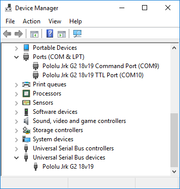 |
Windows 10 Device Manager showing the Jrk G2. |
|---|
3.2. Installing Linux software
To install the software for the Jrk G2 on a computer running Linux, follow these steps:
- Download the version for your system from this list:
- Jrk G2 Software for Linux (x86) (9MB xz) — works on 32-bit and 64-bit systems
- Jrk G2 Software for Linux (Raspberry Pi) (6MB xz) — works on the Raspberry Pi and might work on other ARM Linux systems
- In a terminal, use
cdto navigate to the directory holding the downloaded file. For example, runcd ~/Downloadsif it was downloaded to the “Downloads” folder in your home directory. - Run
tar -xvf pololu-jrk-g2-*.tar.xzto extract the software. If you downloaded multiple versions of the software, you should use an exact file name instead of an asterisk. - Run
sudo pololu-jrk-g2-*/install.shto install the software. You will need to have sudo privilege on your system and you might need to type your password at this point. Look at the output of the script to see if any errors happened. - After the installation has completed, plug the Jrk into your computer via USB. If you already connected the Jrk earlier, unplug it and plug it in again to make sure the newly-installed udev rules are applied.
- Run
jrk2cmd --listto make sure the software can detect the Jrk. This command should print the serial number and product name of the Jrk. If it prints nothing, see the “USB troubleshooting for Linux” section below. - If you are using a graphical desktop environment, run
jrk2guito start the configuration utility. In the upper left corner of the window, where it says “Connected to:”, make sure that it shows something like “18v19 #01234567”. This indicates the version and serial number of the Jrk G2 that the software has connected to. If it says “Not connected”, see the troubleshooting section below.
This Jrk G2 software consists of two programs:
- The Jrk G2 Configuration Utility (jrk2gui) is a graphical user interface (GUI) for configuring the Jrk G2 and viewing its status. You can open a terminal and type
jrk2guito run it. - The Jrk G2 Command-line Utility (jrk2cmd) is a command-line utility that can do most of what the GUI can do, and more. You can open a terminal and type
jrk2cmdwith no arguments to a see a summary of its options.
The Jrk G2 software for Linux is statically linked; it does not depend on any shared libraries. The source code for the software is available. The Jrk G2 does not require any driver installation on Linux.
Software installation troubleshooting for Linux
If you do not have sudo privilege or you do not remember your password, you can skip running install.sh and just run the programs directly from the directory you extracted them to. You should also consider moving the software to a more permanent location and adding that location to your PATH as described below.
If you get a “No such file or directory” error while running ./install.sh, it is possible that your system is missing one of the directories that the install script assumes will be present. Please contact us to let us know about your system so we can consider supporting it better in the future.
If you get the error “command not found” when you try to run jrk2cmd or jrk2gui, then you should run echo $PATH to see what directories are on your PATH, and then make sure one of those directories contains the Jrk executables or symbolic links to them. The installer puts symbolic links in /usr/local/bin, so if that directory is not on your PATH, you should run export PATH=$PATH:/usr/local/bin to add it. Also, you might want to put that line in your ~/.profile file so the directory will be on your PATH in future sessions.
If you get the error “cannot execute binary file: Exec format error” when you try to run jrk2cmd or jrk2gui, then it is likely that you downloaded the wrong version of the software from the list above. If all of the listed versions give you this error, you will probably need to compile the software from source by following the instructions in BUILDING.md in the source code. Please contact us to let us know about your system so we can consider supporting it better in the future.
If the Jrk G2 Configuration Utility window is too big to fit on your screen properly, try setting the JRK2GUI_FONT_SIZE environment variable to “6” before running the software. You can do this by running the command JRK2GUI_FONT_SIZE=6 jrk2gui in your terminal. You can experiment with font sizes other than 6 to see if they work for you. You could also add the line export JRK2GUI_FONT_SIZE=6 to your ~/.profile to make the change permanent.
USB troubleshooting for Linux
If the Jrk G2 software cannot connect to your Jrk after you plug it into the computer via USB, the tips here can help you troubleshoot the Jrk’s USB connection.
If you are using the Jrk G2 Configuration Utility, try opening the “Connected to:” drop-down box to see if there are any entries in the list. If there is an entry, try selecting it to connect to it.
Make sure you have a Jrk G2. The Jrk G2 software does not work with the older Jrk 21v3 or Jrk 12v12. If you have one of those products, you should refer to its user’s guide instead of this user’s guide.
Make sure you are using software that supports the Jrk G2. The original Jrk Configuration Utility does not work with the Jrk G2. The Jrk G2 controllers have new USB product IDs. Third-party software for the older Jrk 21v3 and Jrk 12v12 controllers might need to be updated, depending on how the software works. If you are a developer of such software, see Section 1.2.
If you have connected any electronic devices to your Jrk besides the USB cable, you should disconnect them.
You should look at the LEDs of the Jrk. If the LEDs are off, then the Jrk is probably not receiving power from the USB port. If the green LED is flashing very briefly once per second, then the Jrk is receiving power from USB, but it is not receiving any data. These issues can be caused by using a broken USB port, using a broken USB cable, or by using a USB charging cable that does not have data wires. Using a different USB port and a different USB cable, both of which are known to work with other devices, is a good thing to try. Also, if you are connecting the Jrk to your computer via a USB hub, try connecting it directly.
If the Jrk’s green LED is on all the time or flashing slowly, but you can’t connect to it in the Jrk software, then there might be something wrong with your computer. A good thing to try is to unplug the Jrk from USB, reboot your computer, and then plug it in again.
If you get a “Permission denied” error when trying to connect to the Jrk, you should make sure to copy the 99-pololu.rules file into /etc/udev/rules.d and then unplug the Jrk and plug it back in again. The install script normally takes care of installing that file for you.
If that does not help, you should try running lsusb to list the USB devices recognized by your computer. Look for the Pololu vendor ID, which is 1ffb. You should also try running dmesg right after plugging in the Jrk to see if there are any messages about it.
3.3. Installing macOS software
To install the configuration software for the Jrk G2 on a computer running macOS, follow these steps:
- Download the Jrk G2 Software for macOS (8MB pkg).
- Double-click on the downloaded file to run it, and follow the instructions.
- After the installation has completed, plug the Jrk into your computer via USB.
- In your Applications folder, look for “Pololu Jrk G2”. Double-click on “Pololu Jrk G2” to start the configuration utility.
- In the upper left corner of the window, where it says “Connected to:”, make sure that it shows something like “18v19 #01234567”. This indicates the version and serial number of the Jrk G2 that the software has connected to. If it says “Not connected”, see the troubleshooting section below.
This Jrk G2 software consists of two programs:
- The Jrk G2 Configuration Utility (jrk2gui) is a graphical user interface (GUI) for configuring the Jrk G2 and viewing its status. You can run it by clicking on “Pololu Jrk G2” in the Applications folder, or you can open a terminal and type
jrk2guito run it. - The Jrk G2 Command-line Utility (jrk2cmd) is a command-line utility that can do most of what the GUI can do, and more. You can open a terminal and type
jrk2cmdwith no arguments to a see a summary of its options.
The source code for the software is available. The Jrk G2 does not require any driver installation on macOS.
Software installation troubleshooting for macOS
If you get the error “command not found” when you try to run jrk2cmd or jrk2gui, then you should try starting a new Terminal window. The installer adds a file named 99-pololu-jrk2 in the /etc/paths.d directory to make sure the software gets added to your PATH, but the change will not take effect until you open a new Terminal window.
The Jrk G2 software will not work on versions of macOS prior to 10.11.
USB troubleshooting for macOS
If the Jrk G2 software cannot connect to your Jrk after you plug it into the computer via USB, the tips here can help you troubleshoot the Jrk’s USB connection.
If you are using the Jrk G2 Configuration Utility, try opening the “Connected to:” drop-down box to see if there are any entries in the list. If there is an entry, try selecting it to connect to it.
Make sure you have a Jrk G2. The Jrk G2 software does not work with the older Jrk 21v3 or Jrk 12v12. If you have one of those products, you should refer to its user’s guide instead of this user’s guide.
Make sure you are using software that supports the Jrk G2. The original Jrk Configuration Utility does not work with the Jrk G2. The Jrk G2 controllers have new USB product IDs. Third-party software for the older Jrk 21v3 and Jrk 12v12 controllers might need to be updated, depending on how the software works. If you are a developer of such software, see Section 1.2.
If you have connected any electronic devices to your Jrk besides the USB cable, you should disconnect them.
You should look at the LEDs of the Jrk. If the LEDs are off, then the Jrk is probably not receiving power from the USB port. If the green LED is flashing very briefly once per second, then the Jrk is receiving power from USB, but it is not receiving any data. These issues can be caused by using a broken USB port, using a broken USB cable, or by using a USB charging cable that does not have data wires. Using a different USB port and a different USB cable, both of which are known to work with other devices, is a good thing to try. Also, if you are connecting the Jrk to your computer via a USB hub, try connecting it directly.
If the Jrk’s green LED is on all the time or flashing slowly, but you can’t connect to it in the software, then there might be something wrong with your computer. A good thing to try is to unplug the Jrk from USB, reboot your computer, and then plug it in again.
Another thing to try is to run dmesg right after plugging in the Jrk to see if there are any messages about it.
4. Basic setup
4.1. Choosing the motor, power supply, and Jrk
The information in this section can help you select a motor, a power supply, and a Jrk G2 controller that will work well together.
The Jrk requires a DC power supply. The Jrk is designed to drive a brushed DC motor, either by itself or as part of a device like a linear actuator.
Voltage and current ratings
When selecting your motor, power supply, and Jrk controller, you must consider the voltage and current ratings of each.
The rated voltage of a DC motor is the voltage it was designed to run at, and this is the voltage at which it will draw its rated currents. It is fine to drive a motor with a lower voltage than what it is rated for, in which case its current draw will be proportionally lower, as well as its speed and torque. Conversely, using a higher-than-rated voltage will result in proportionally higher current draw, speed, and torque, and could negatively affect the lifetime of the motor. However, you can limit the PWM duty cycle used to drive the motor to keep its average current draw within rated limits. (For example, running a 6 V motor at 12 V but limiting its duty cycle to a maximum of 50% should generally be OK).
The stall current of a DC motor is how much current the motor will draw when power is applied but it is not spinning (for example, if the motor shaft is prevented from rotating), producing maximum torque and minimum (zero) speed. The stall current depends on the voltage that is applied to the motor, and the stall current is usually measured at the rated voltage of the motor. Most brushed DC motors are not designed to be stalled for extended periods and can be damaged if they are.
It is not unusual for the stall current of a motor to be an order of magnitude (10×) higher than its free-run current. When a motor is supplied with full power from rest, it briefly draws the full stall current, and it draws nearly twice the stall current if abruptly switched from full speed in one direction to full speed in the other direction.
The free-run current of a DC motor (or no-load current) is how much current the motor draws when it is running freely, producing maximum speed and minimum torque (since there is no external opposing torque). Like the stall current, the free-run current depends on the voltage that is applied to the motor, and is usually measured at the rated voltage of the motor.
The voltage range of your power supply is the range of voltages you expect your power supply to produce while operating. There is usually some variation in the output voltage so you should treat it as a range instead of just a single number. In particular, keep in mind that a fully-charged battery might have a voltage that is significantly higher than its nominal voltage.
The current limit of a power supply is how much current the power supply can provide. Note that the power supply will not force this amount of current through your system; the properties of the system and the voltage of the power supply determine how much current will flow, but there is a limit to how much current the power supply can provide.
The minimum operating voltage of a Jrk is the lowest voltage that is acceptable for the Jrk’s motor power supply. If you try to power the Jrk with a voltage lower than this, it might fail to deliver power to the motor, but it should not cause any permanent damage.
The absolute maximum operating voltage of a Jrk is the maximum voltage that can be tolerated by the Jrk. If the voltage of the power supply rises above this voltage, even for just a brief period of time, the Jrk could be permanently damaged.
The recommended maximum operating voltage of a Jrk is the maximum voltage we recommend using for the Jrk’s motor power supply. We have chosen this number to be significantly lower than the absolute max operating voltage so that if there is noise on the power supply it is unlikely to exceed the absolute max operating voltage.
The maximum nominal battery voltage of a Jrk is the maximum nominal voltage we recommend using for batteries that supply power to the Jrk. We have chosen this number to be significantly lower than the recommended maximum operating voltage because fully-charged batteries can have a voltage that is significantly higher than their nominal voltage.
The maximum continuous current of a Jrk indicates the motor current that it can continuously supply without overheating in typical conditions (at room temperature with no additional cooling). The Jrk’s MOSFETs can handle large current spikes for short durations (e.g. 100 A for a few milliseconds), and the Jrk’s hardware current limit can be configured to help it handle large transients, such as when starting a motor. However, note that the Jrk does not have an over-temperature shut-off. (The Jrk’s motor driver error can indicate an over-temperature fault, but the Jrk does not directly measure the temperature of the MOSFETs, which are usually the first components to overheat.) As a result, an over-temperature or over-current condition can still cause permanent damage.
The voltage and current ratings of the different Jrk G2 controllers are shown in the table below.
| Jrk G2 21v3 | Jrk G2 18v19 | Jrk G2 24v13 | Jrk G2 18v27 | Jrk G2 24v21 | |
|---|---|---|---|---|---|
| Minimum operating voltage: |
4.5 V(1) | 6.5 V | 6.5 V | 6.5 V | 6.5 V |
| Absolute max operating voltage: |
40 V(2) | 30 V | 40 V | 30 V | 40 V |
| Recommended max operating voltage: |
28 V | 24 V | 34 V | 24 V | 34 V |
| Max nominal battery voltage: |
24 V | 18 V | 28 V | 18 V | 28 V |
| Max continuous current (no additional cooling): |
2.6 A | 19 A | 13 A | 27 A | 21 A |
1 The 5V logic voltage drops when powered from a supply below about 5.2 V.
2 Operation from 28 V to 40 V should be transient (< 500 ms).
These are the main constraints you should keep in mind when selecting your power supply, Jrk controller, and motor:
- The voltage of your power supply should ideally be greater than or equal to the rated voltage of your motor so that you can get the full performance that the motor is capable of. It is OK for the power supply voltage to be higher than the rated voltage of the motor, but if it is significantly higher then you should consider configuring the Jrk’s maximum duty cycle limits in order to limit the voltage applied to the motor.
- The voltage of your power supply should be within the operating voltage range of the Jrk. Otherwise, the Jrk could malfunction or (in the case of high voltages) be damaged.
- The maximum continuous current of the Jrk and the current limit of the power supply should ideally be greater than or equal to the stall current of the motor. However, this might be impractical or unnecessary in some applications, especially with high-power motors that are not intended to be stalled for prolonged periods (and will be damaged if they are). If so, you should at least make sure that both current ratings are greater than the free-run current of the motor. The higher the stall current of your motor, the more important it is to consider using the Jrk’s acceleration limiting and hardware current limiting to prevent the motor from drawing too much current.
4.2. Connecting the motor and power supply
The information in this section can help you connect your motor and power supply to the Jrk G2.
Warning: This product is not designed to or certified for any particular high-voltage safety standard. Working with voltages above 30 V can be extremely dangerous and should only be attempted by qualified individuals with appropriate equipment and protective gear.
Warning: This product can get hot enough to burn you long before the chips overheat. Take care when handling this product and other components connected to it.
It is a good practice to check that things are working in small chunks, rather than doing your first checks after you have spent hours making a complicated system. Before connecting anything to the Jrk, we recommend connecting it to USB and running the Jrk G2 Configuration Utility, as described in Section 3.
Before connecting anything else, disconnect the Jrk from USB. Generally, rewiring anything while it is powered is asking for trouble.
You can solder the terminal blocks that come with the Jrk to the four large through-holes to make your motor and power connections, or you can solder an 8-pin piece of the 0.1″ header strip (which also comes with the Jrk) into the smaller through-holes that border these larger holes. Note, however, that the terminal blocks are only rated for 16 A, and each header pin pair is only rated for a combined 6 A, so for higher-power applications, we recommend soldering thick wires directly to the board. If you have a Jrk G2 21v3 with connectors already soldered, then you do not need to solder anything to the Jrk to make your motor and power connections.
|
|
||||
|
|
||||
|
|||||
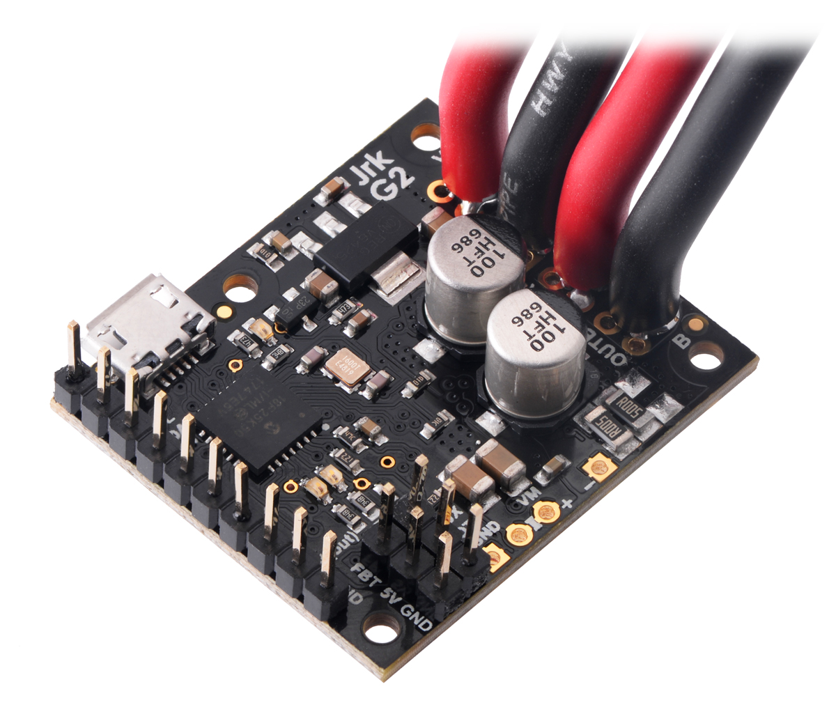
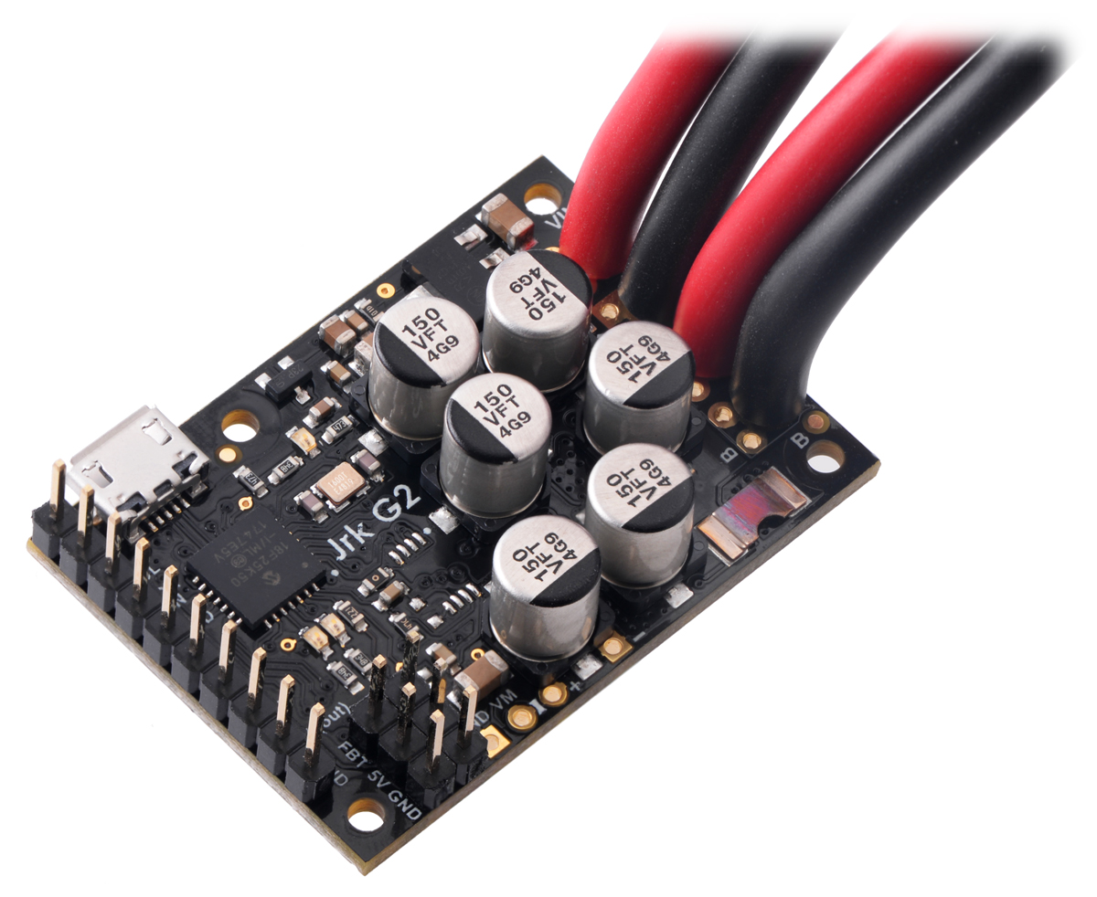

You should connect the motor leads to the OUTA and OUTB pins (which are labeled “A” and “B” on some boards). You should connect the negative terminal of the power supply to GND and the positive terminal of the power supply to VIN.
Next, turn on the power supply (if needed). Make sure that the Jrk’s yellow or red LEDs turn on at this point. If neither LED turns on, you might have connected power backwards, and you should fix it before connecting the Jrk to any other electronics.
4.3. Configuring and testing the motor
This section explains how to configure and test your motor over USB using the Jrk G2 Configuration Utility, without using feedback. It is a good idea to test the motor like this to make sure that the motor is working and that you can get the desired performance out of it before you try to set up feedback or a different input mode. Of course, this requires that you have a system that does not destroy itself when run without feedback.
If you have not done so already, you should connect your motor and power supply to the Jrk G2 as described in Section 4.2. Then, connect the Jrk to your computer via USB, open Jrk G2 Configuration Utility, and connect to the Jrk.
If you have changed any of the settings of your Jrk, you should probably reset the Jrk to its default settings by opening the “Device” menu and selecting “Restore default settings”. Then, make sure the “Input mode” is set to “Serial / I²C / USB” (in the “Input” tab) and make sure the “Feedback mode” is set to “None” (in the “Feedback” tab).
The “Motor” tab has several settings that affect the behavior of the motor. For your initial tests, we recommend changing a few of these settings to safe values to help avoid damage:
- Set the “Max. duty cycle” to a safe value, like 200 (33%).
- Set the “Max. acceleration” to a safe value, like 6. (It will take 100 PID periods, or 1 second, for the motor to reach a duty cycle of 600 (100%).)
- For now, you should probably leave the “Max. deceleration” set to its default value of 600 so that the Jrk will always stop the motor immediately when commanded.
- If there is a “Hard current limit” setting, set it to a safe value, like 3 A. (The Jrk G2 21v3 does not have configurable hardware current limiting so that setting is hidden. Its TB9051FTG motor driver always limits the current to approximately 6.5 A.)
In the “Errors” tab, set the “No power” error to enabled and latched so that your system will stop if there is a power issue and not automatically start running again until you command it to.
You might want to set other limits as necessary. You can read more about the motor settings in Section 7.6.
Click “Apply settings” to apply the new settings to the Jrk.
Click the “Run motor” button to clear any latched errors. The message at the bottom of the Jrk G2 configuration utility should now say “Motor stopped.”. If that message indicates errors instead, you can find out what errors are stopping the motor by looking in the “Errors” tab. You will need to fix those errors before you can test your motor.
You can use the slider in the “Manually set target” box to try out some different duty cycles. The slider controls the “Target” variable, and the Jrk will set the duty cycle to the target minus 2048, after accounting for the limits you have configured. A target of 2048 corresponds to the motor being stopped. One way to set the target to 2048 is to click the “Center” button. You can also stop the motor at any time by clicking the “Stop motor” button.
The green dot on the slider shows the duty cycle (plus 2048). This makes it easy to see if the Jrk’s duty cycle is different from its duty cycle target due to motor limits.
If you have a concept of “forward” for your system but the motor does not go in that direction when you drive it with positive duty cycles, you might want to swap the motor leads or enable the “Invert motor direction” option in the “Motor” tab.
If everything goes well, you should try increasing your “Max. duty cycle”, “Max. accleration”, “Hard current limit”, and other limits in to reasonable values for high-performance operation of your system. If possible, make sure you can get the desired performance out of your motor before setting up feedback.
5. Setting up the feedback method
5.1. Setting up open-loop control
To configure the Jrk G2 for open-loop speed control, you should open the Jrk G2 Configuration Utility, go to the “Feedback” tab, and set the “Feedback mode” to “None” (which is the default). We also recommend following the instructions in Section 4.3 to configure and test your motor.
When the “Feedback mode” is “None”, the Jrk calculates its “Duty cycle target” variable by simply subtracting 2048 from the “Target” variable. So a target of 2048 corresponds to the motor being off, while a target of 2648 corresponds to full speed forward (100%), and a target of 1448 corresponds to full speed reverse (−100%).
You can set the target directly over USB, serial, or I²C, or you can configure the Jrk to calculate the target by scaling the reading from an analog or RC input. If you are using an analog or RC input, you will probably want to configure the input scaling settings to map all input values to targets within the 1448 to 2648 range, so that more of your input range is usable. There is more information about setting up the scaling settings in Section 6.4 and Section 6.5.
5.2. Setting up analog feedback
This section explains how to connect an analog feedback signal to the Jrk G2 and configure the Jrk G2 to do position control. Please note that this is different from setting up an analog control signal, which is documented in Section 6.4.
Connecting analog feedback
If you have not done so already, you should follow the instructions in Section 4.3 to configure and test your motor. Next, with the system unpowered, connect your analog feedback signal to the Jrk as described below.
If you are using a potentiometer to generate the analog feedback signal, then you should connect the potentiometer’s wiper to FBA. You should connect the other two ends of the feedback potentiometer to the power pins that are in line with FBA: on the Jrk G2 18v27 and 24v21, the pins are AUX and GND, while on the other Jrk G2 versions the pins are AUX and POT−.
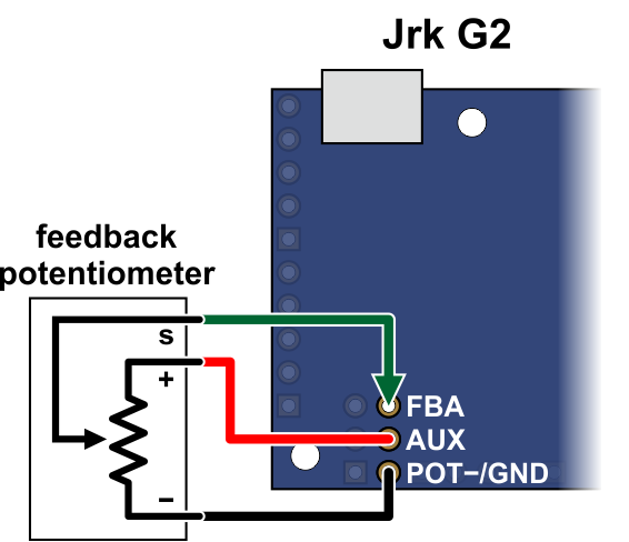 |
Connecting analog voltage feedback to the Jrk G2. |
|---|
If you are using something other than a potentiometer to generate the analog feedback signal, make sure that the ground node of that device is connected to a GND pin of the Jrk, and that the signal from that device is connected to the FBA pin. The Jrk can only accept signals between 0 V and 5 V with respect to GND; signals outside of this range could damage the Jrk.
Configuring and calibrating analog feedback
Now connect your Jrk to your computer via USB. In the Jrk G2 Configuration Utility, go to the “Feedback tab” and set the “Feedback mode” to “Analog voltage”.
If you are powering a feedback potentiometer from the AUX pin, you should check the “Detect disconnect with power pin (AUX)” checkbox. This causes the Jrk to drive AUX low periodically to help detect whether the feedback potentiometer has been disconnected.
Go to the “Errors” tab and set the “Feedback disconnect” error to “Enabled and latched”. Click the “Apply settings” button.
Turn on motor power.
Go to the “Feedback” tab, and in the “Scaling” box, click “Feedback setup wizard…”.
Steps 1 and 2 of the feedback setup wizard helps you configure the direction of your motor and the direction of your feedback. These steps ensure that a positive duty cycle corresponds to the motor moving in the direction that you consider to be forward in your system, and that this forward movement also causes the Jrk’s “Scaled feedback” variable to increase.
Step 3 of the feedback setup wizard lets you set the range of your feedback.
If possible, the range you enter in step 3 should be at least a little larger than the range of motion that you actually plan on using. Raw feedback values within this range get mapped to “Scaled feedback” values from 0 to 4095. Raw feedback values outside of the range will be mapped to a “Scaled feedback” value of either 0 or 4095, depending on whether they are below or above the range. The Jrk’s PID algorithm does not look at the raw feedback variable: it compares the “Scaled feedback” to the “Target” and drives the motor in attempt to eliminate the difference between those two, also known as the “Error”. If you set the “Target” to 0 or 4095 but something pulls your system outside of the feedback range entered in step 3, the “Scaled feedback” variable will not change so the Jrk will not know it should drive the motor to get the system back within the desired range.
Once you have finished the wizard, the new settings should be applied to the Jrk.
Testing basic feedback
At this point, the Jrk is almost ready to do position control. Go to the “PID” tab and enter a “Proportional coefficient” of 1, while leaving the other two coefficients set to zero. This will probably drive your motor at its maximum duty cycle, so make sure that this and other motor parameters are configured correctly. Click “Apply settings”.
Use the target slider at the bottom of the window to send various target values to your Jrk, and see how it behaves. The red dot on the slider shows the “Scaled feedback” value.
If you did everything correctly, your feedback system should now be active, approximately following the target value.
Troubleshooting basic feedback
If the steps above do not result in a working position feedback system, these tips can help you figure out what is wrong and get the system working.
First of all, look in the “Errors” tab and look at the status message at the bottom of the Jrk G2 Configuration Utility. These messages might tell you why things are not working.
It is possible that you did not do one of the steps of the Feedback wizard correctly. You might consider trying the wizard again and carefully reading each instruction.
To troubleshoot effectively, you should know a little bit about how the Jrk’s PID algorithm works.
- During each PID update period (which is 10 ms by default), the Jrk measures the analog voltage on the FBA pin and uses that to set the (raw) “Feedback” variable, which you can see in the Status tab of the Jrk Configuration Utility. A value of 0 should represent 0 V, while a value of 4092 represents approximately 5 V.
- The Jrk scales the raw feedback value using the scaling settings from the “Feedback” tab in order to compute the “Scaled feedback” value, which is also a number between 0 and 4095. Raw feedback values above the “Maximum” feedback value get mapped to a “Scaled feedback” value of 4095 (if the feedback direction is not inverted) or 0 (if the feedback direction is inverted. Raw feedback values below the “Minimum” feedback value get mapped to a “Scaled feedback” value of 0 (if the feedback direction is not inverted) or 4095 (if the feedback direction is inverted).
- The Jrk’s PID algorithm calculates the “Scaled Feedback” minus the “Target” (which is called the Error), multiplies it by the proportional coefficient, then multiplies by −1, and assigns that value to the “Duty cycle target” variable (assuming the derivative and integral coefficients are zero). A “Duty cycle target” of −600 represents full speed reverse while a “Duty cycle target” of 600 represents full speed forward, but the target can be outside of this range. A proportional coefficient of 1 means that the “Target” and “Scaled feedback” have to differ by 600 counts before the Jrk will drive the motor at full speed.
- The Jrk applies max duty cycle, max acceleration, and other motor limits to the “Duty cycle target” to produce the “Duty cycle” variable between −600 (full speed reverse) and 600 (full speed forward).
- The Jrk drives the motor at the specified duty cycle. The direction of the motor is determined by the sign of the “Duty cycle” variable and the “Invert motor direction” setting, which was determined in step 1 of the feedback setup wizard.
The “Status” tab displays the “Feedback”, “Scaled feedback”, “Target”, “Error”, “Duty cycle target”, and “Duty cycle” variables so you can see what is happening at each step of this process and figure out exactly where things are going wrong:
- Measure the analog voltage on the FBA pin with respect to GND and make sure it accurately reflects the position of your system.
- Compare those measurements to the “Feedback” variable, and make sure it accurately reflects the voltage on the FBA pin as described above.
- Make sure that the “Scaled feedback” values goes to roughly 4095 at your system’s extreme forward position (according to your definition of forward for your system), and goes to roughly 0 at your system’s extreme reverse position. If not, the feedback scaling settings should probably be adjusted.
- Make sure that the “Duty cycle target” is equal to the “Target” minus the “Scaled feedback” (assuming your proportional coefficient is 1 and the other coefficients are 0).
- Make sure that the “Duty cycle” responds properly to changes in the “Duty cycle target”. If the “Duty cycle” is not being calculated properly, check the limits in the “Motor” tab.
- Make sure that the “Duty cycle” goes below −150 (−25%) or above 150 (25%) when you try to drive the motor, or else you might not be applying enough power to actually move the motor.
- Make sure that when the motor is moving, a positive duty cycle corresponds to forward movement (according to your definition of forward for your system), while a negative duty cycle corresponds to reverse movement. If this is not the case, you should toggle the “Invert motor direction” checkbox in the “Motor” tab or retry the feedback setup wizard.
- Make sure that when the motor is moving with a positive duty cycle, the scaled feedback value is increasing, and that when the motor is moving with a negative duty cycle, the scaled feedback value is decreasing. If this is not the case, you should toggle the “Invert feedback direction” checkbox in the “Feedback” tab or retry the feedback setup wizard.
Tuning the PID coefficients
After getting a basic feedback system working, you might want to tune it for better performance. Tuning PID constants is a complicated process that can be approached in many different ways. Here we will give a basic procedure that works for some systems, but you will probably want to try various different methods for finding the best possible values. You will want to have the graph window open, displaying a nice view of the Error, Target, Scaled feedback, and Duty cycle. When setting the Integral coefficient, it will also be useful to look at the value of the Integral.
- Increase your “Max. duty cycle”, “Hard current limit”, and other limits to reasonable values for high-performance operation of your system.
- Try increasing the Proportional coefficient until you reach a point where the system becomes unstable. Note that the stability could be different at different target positions, so try the full range of motion when hunting for instability.
- Decrease the value from the point of instability by about 40-50%. This is the first step of the Ziegler-Nichols Method.
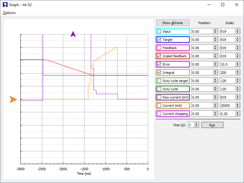 |
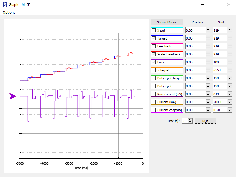
- Note how close your system gets to an error of zero using just the proportional term. You can use the integral term to get it much lower: with the integral limit set at 1000, try increasing the Integral coefficient until you see a correction that brings the error closer to zero. In the graph window shown here, you can see that the proportional term gets the error down to about 4, then the integral term builds up and, half a second later, moves the motor just a bit, reducing the error to 0.
- For systems that have a lot of friction relative to external forces, enable a “Feedback dead zone” so that the integral term doesn’t cause a slow oscillation very close to an error of zero. Watch how the integral term and duty cycle build up over time to achieve this. In this example, if the first adjustment had only reduced the error to 1, we might have considered setting a dead zone of 2 to prevent the integral term from continuing to build up at a slower rate.
- Enable the “Reset integral when proportional term exceeds max duty cycle” option to prevent the integral from winding up during large motions. This is also shown in the graph: the integral term does not start increasing until the error is close to zero.
 |
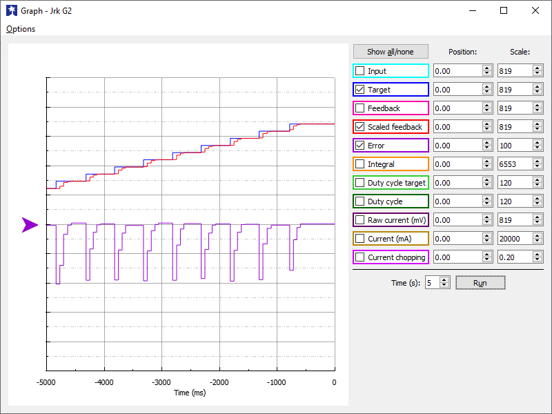
- Have your system take large steps (for example, by clicking the bar area of the Input tab scrollbar to move the target by 200) and use the graph to examine whether it consistently overshoots (the error crosses zero before coming to a stop and moving back) or undershoots (the error does not reach zero before slowing down). The graph window shown here, drawn for a system using a Derivative coefficient of zero, shows clear overshooting. In this example, the error actually oscillates back and forth several times before settling down.
 |
- Increase the Derivative coefficient to get rid of any overshooting, but not so much that it undershoots. The graph window shown here demonstrates undershooting, using a Derivative coefficient of 25. You can see that the error does not quickly reach zero. Instead, it gradually approaches zero after each step.
- Experiment with your system. Adjust any parameters as necessary to get the behavior that you need.
The following example plot shows a well-tuned system, with Proportional, Integral, and Derivative coefficients of 6.0, 0.25, and 12. When taking steps, the system stops very quickly at a position with very small error, only overshooting or undershooting by a small amount.
 |
5.3. Setting up frequency feedback
This section explains how to connect a frequency feedback signal to the Jrk G2 and configure the Jrk G2 to do PID speed control. Please note that this is different from setting up RC control, which is documented in Section 6.5.
Also, please note that the Jrk cannot detect the direction your motor is moving in this mode. It will measure the frequency on FBT using one of the methods described below and set the “Feedback” variable to 2048 plus or minus the frequency measurement (restricted to be between 0 and 4095). It will use “plus” if the “Target” variable (which specifies the desired speed) is 2048 or more, and it will use “minus” otherwise.
Connecting frequency feedback
If you have not done so already, you should follow the instructions in Section 4.3 to configure and test your motor. Next, with the system unpowered, connect your frequency feedback signal to the Jrk as described below.
You should connect the frequency feedback signal to the Jrk’s FBT pin. The Jrk will measure the signal on this line as a digital input. The voltage on FBT should be between 0 V and 5 V with respect to GND; signals outside of this range could damage the Jrk. The FBT pin is pulled up to 5 V by an on-board 100kΩ resistor.
 |
Connecting tachometer feedback to the Jrk G2. |
|---|
The sensor’s ground pin should be connected to a GND pin on the Jrk, and you can also use the nearby 5V pin to the power the sensor if needed.
If you are using one channel of a quadrature encoder to do speed control on the Jrk G2, here are some things to keep in mind:
- The Jrk G2 does not support position control with a quadrature encoder; this section is only about setting up speed control.
- The Jrk can only use one of the two signals from the quadrature encoder. That signal should be connected to FBT, while the other one is left disconnected.
Configuring frequency feedback
Now connect your Jrk to your computer via USB. In the Jrk G2 configuration utility, go to the “Feedback tab” and set the “Feedback mode” to “Frequency (speed control)”. Also, if you changed any of the settings in the “Scaling” box, you should make sure to uncheck the “Invert feedback direction” box and click the “Reset to full range” button to effectively turn off feedback scaling.
You will also need to pick your frequency feedback measurement method and configure the other frequency feedback settings appropriately. The Jrk G2 supports two measurement methods: “Pulse counting” and “Pulse timing”, and they are documented below.
Determining the tachometer frequency range
It is important to know what range of frequencies you expect to get out of your motor/tachometer setup before proceeding. The frequency that matters is the number of pulses on the FBT pin per second. For example, if you expect 1500 pulses on the FBT pin per second, that would be a frequency of 1500 Hz, which can also be written as 1.5 kHz.
You should refer to the documentation of your motor/tachometer setup, while also considering your power supply and desired speed range, in order to calculate the frequency range. Keep in mind that if the encoder documentation indicates that the encoder is, say, 12 CPR (12 counts per revolution), that actually means 3 pulses per revolution for the purpose of Jrk frequency feedback. This factor of 4 difference (between 12 and 3) is because the Jrk G2 is only measuring one of the two signal lines, and there are two encoder counts per pulse. You will also need to know whether the encoder is connected to the output shaft of the motor or a high-speed shaft on the rear of the motor, since that affects whether you need to account for the gear ratio (by dividing or multiplying by it) in your calculation.
Pulse counting mode (faster tachometers)
In this mode, the Jrk G2 will count the number of rising edges that happen on the FBT pin each PID period (which is 10 ms by default).
With the default settings, the Jrk will set the “Feedback” variable to 2048 plus or minus the number of rising edges that happened on the FBT pin in the last PID period, which is 10 ms.
These default pulse counting settings are probably not appropriate if you want to do speed control at frequencies below 5 kHz. At frequencies below 5 kHz, there would be fewer than 50 pulses during each 10 ms PID period. It might be difficult to achieve good PID speed control results when working with such small numbers. Therefore, if you need to measure frequencies slower than 5 kHz, you should probably use pulse timing mode, which is described later in this section.
In pulse counting mode, the “Pulse samples” setting is the number of consecutive pulse counts to add together. The default pulse samples value is 1, and it can be set to any whole number between 1 and 32. For example, with a value of 8, the Jrk will set the “Feedback” variable to 2048 plus or minus the number of pulses in the last 8 PID periods. This can help with measuring lower frequencies, but would also lower the response time of the Jrk since the “Feedback” variable would be considering the speed over a longer period of time. Another way to get more counts in pulse counting mode is to increase the PID period.
The frequency measurement is divided by the value of the “Frequency divider” setting before it is added to or subtracted from 2048 in the calculation of the “Feedback” variable. If your tachometer is fast enough that you expect to get more than 2047 counts per PID period (which would saturate the “Feedback” variable, since it is limited to be between 0 and 4095), you can increase the frequency divider, allowing you to measure a more frequencies on the high end, but also reducing your ability to measure lower frequencies.
Pulse timing mode (slower tachometers)
In this mode, which is appropriate for most of our gearmotor/encoder products, the Jrk G2 will measure the width (duration) of pulses and calculate the corresponding frequency by taking the reciprocal of the pulse width (scaled by various constants). The Jrk will set the “Feedback” variable to 2048 plus or minus this calculated frequency.
The “Pulse samples” setting, which can be set to any whole number between 1 and 32, determines how many pulse widths the Jrk will average together when calculating the frequency. It is generally a good idea to learn how your encoder works and set this setting appropriately to cancel out physical variations in the encoder, which could cause the pulse widths to vary. For example, consider a 12 CPR (counts per revolution) encoder that is based on a rotating disk with three slots. Since the three slots will have slightly different widths, you might want to set “Pulse samples” to 3 in order to average the last 3 pulses, which would imply you are measuring one pulse from each slot, and thus any variation you see in the averaged pulse width is due to the speed changing, instead of which slot the Jrk happens to see last before doing PID calculations. If your tachometer frequency is close to or higher than your PWM frequency (20 kHz or 5 kHz), then the Jrk might miss some pulses, and that could defeat the point of this averaging because the average would no longer come from consecutive pulses.
The “Pulse timing polarity” setting determines whether to measure low pulses or high pulses. The default is “Active high”, which means the Jrk is measuring high pulses. If the low pulses produced by your tachometer have less variation than the high pulses (in terms of percentage change), it would make sense to change the polarity to “Active low” so the Jrk can measure the low pulses and therefore have less variation in its readings.
The “Pulse timing timeout” setting lets you specify a timeout in milliseconds. When the Jrk has not recorded any pulses in the specified amount of time, it records a maximum-width pulse (65535 in units of pulse timing clock ticks). This mechanism is what allows the Jrk’s “Feedback” variable to reset when the motor has stopped. You can generally leave this setting alone. If you decrease it below its default value of 100 ms, it might affect the lower range of the frequencies you can measure.
The “Pulse timing clock” is the frequency of the 16-bit timer that is used to measure pulses. This clock speed matters because the Jrk cannot measure any pulses that are longer than 65535 divided by the pulse timing clock. For example, at 1.5 MHz the slowest pulse it can measure is 65535 divided by 1.5 MHz (43 ms), which corresponds to a tachometer frequency of 1.5 MHz divided by 65535 divided by 2, or 11.4 Hz. The factor of 2 in the calculation comes from the fact that the Jrk only measures one of the two pulses (either the high one or the low one) during each period of the tachometer signal, and we are assuming that the high and low pulses are roughly equal, so each pulse has a 50% duty cycle. (The Jrk’s pulse timing frequency feedback can work with signals where the high and low pulses are not equal, but many of the calculated frequency numbers in this section would be inaccurate in that case.)
The Jrk will measure a pulse width (or average together multiple pulse widths) in units of the pulse timing clock ticks, and it will be a number between 0 and 65535 (0xFFFF). To convert this pulse width to a frequency, it will take 2 raised to the power of 26 (0x4000000, or 67,108,864) and then divide it by the pulse width. It will then divide this reading by the “Frequency divider” setting, which is a power of two between 1 and 32768. Finally, it adds or subtracts the reading from 2048 in order to set the “Feedback” variable, which is constrained to be within 0 to 4095.
Therefore, there are two settings that determine what range of frequencies you can measure in pulse timing mode: the “Pulse timing clock” setting and the “Frequency divider” setting. The Jrk G2 Configuration Utility takes these two settings into account when it calculates the frequency measurement range, which you can see in the “Feedback” tab, after you have set the feedback mode to “Frequency”. This frequency measurement range is not absolute: it makes some assumptions about how much resolution you would want to have in the pulse width and frequency measurements. However, it should give you a good estimate of what frequencies you can expect to measure with your selected pulse timing settings.
To choose your “Pulse timing clock” and “Frequency divider” settings, we recommend following this procedure, while looking at the displayed frequency measurement range:
- Set the “Frequency divider” to 32, while leaving the “Pulse timing clock” at its default value of 1.5 MHz. This should give you a frequency measurement range of 17.9 Hz to 715 Hz.
- If you do not need to measure frequencies as high 715 Hz, try decreasing the frequency divider one step at a time (which basically just lowers the upper end of the range), while making sure the frequency measurement range still contains all the frequencies you care about measuring. This will give you more resolution when converting the pulse width reading to a feedback value, allowing the PID algorithm to work with more counts.
- If you need to measure frequencies higher than 715 Hz, start increasing the “Pulse timing clock” until the frequency measurement range contains all the frequencies you care about measuring. Once you achieve this, you should not increase the clock frequency any further, since that will reduce your ability to measure low frequencies. The highest frequency you can measure with this method is 22.9 kHz.
- If you need to measure frequencies higher than 22.9 kHz, leave the pulse timing clock at its maximum value of 48 MHz and start increasing the frequency divider.
The table below shows the settings you can arrive at by following this procedure, and some of the resulting properties of the Jrk’s frequency measurement system:
| Pulse timing clock |
Frequency divider |
Raw pulse width range |
Feedback range (forward) |
Frequency measurement range (assuming 50% duty cycle) |
|---|---|---|---|---|
| 1.5 MHz | 1 | 58982 to 33554 | 3185 to 4048 | 12 Hz to 22 Hz |
| 1.5 MHz | 2 | 58982 to 16777 | 2616 to 4048 | 12 Hz to 44 Hz |
| 1.5 MHz | 4 | 58982 to 8388 | 2332 to 4048 | 12 Hz to 89 Hz |
| 1.5 MHz | 8 | 58982 to 4194 | 2190 to 4048 | 12 Hz to 178 Hz |
| 1.5 MHz | 16 | 58982 to 2097 | 2119 to 4048 | 12 Hz to 357 Hz |
| 1.5 MHz | 32 | 41943 to 1048 | 2098 to 4048 | 17 Hz to 715 Hz |
| 3 MHz | 32 | 41943 to 1048 | 2098 to 4048 | 35 Hz to 1.43 kHz |
| 6 MHz | 32 | 41943 to 1048 | 2098 to 4048 | 71 Hz to 2.86 kHz |
| 12 MHz | 32 | 41943 to 1048 | 2098 to 4048 | 143 Hz to 5.72 kHz |
| 24 MHz | 32 | 41943 to 1048 | 2098 to 4048 | 286 Hz to 11.4 kHz |
| 48 MHz | 32 | 41943 to 1048 | 2098 to 4048 | 572 Hz to 22.9 kHz |
| 48 MHz | 64 | 20971 to 524 | 2098 to 4048 | 1.14 kHz to 45.8 kHz |
| 48 MHz | 128 | 10485 to 262 | 2098 to 4048 | 2.29 kHz to 91.6 kHz |
| 48 MHz | 256 | 5242 to 131 | 2098 to 4048 | 4.58 kHz to 183 kHz |
| 48 MHz | 512 | 2621 to 65 | 2098 to 4048 | 9.16 kHz to 369 kHz |
| 48 MHz | 1024 | 1310 to 50 | 2098 to 3358 | 18.3 kHz to 480 kHz |
The frequency measurement range shown in the table above (which is the same as the range shown in the Jrk G2 Configuration Utility) and the other numbers reported in the right three columns of this table are not absolute limits. These numbers were made using some assumptions about how much resolution you want to have in the pulse width and frequency measurements. However, these numbers should give you a good estimate of what frequencies you can expect to measure with different pulse timing settings. The numbers in the table were calculated with the assumption that the pulse timing timeout is set to its default value of 100 ms or higher.
Setting initial PID coefficients
You will need to set PID coefficients to make the Jrk respond to the frequency feedback. In frequency feedback mode, the Jrk’s integral coefficient serves the same role that the proportional coefficient does in PID position feedback: it accumulates errors in the measured speed over time, so it is actually a measurement of a position error. So the first step to setting up PID coefficients is to set the integral coefficient, while leaving the proportional and derivative coefficients set to zero. In some of our tests, we found that a good starting point is to set the “Integral limit” setting to something high like 32000 (or its maximum value of 32768), and then set a relatively low integral coefficient, like 0.03125 (1/32). You should also disable the “Reset integral when proportional term exceeds max duty cycle” option and make sure the “Feedback dead zone” is set to 0.
Testing frequency feedback
After you set up your frequency measurement settings and initial PID coefficients, you should test the frequency feedback by dragging the slider at the bottom of the window and looking at the variables in the “Status” tab. You should open the graph window in the Jrk G2 Configuration Utility and plot the “Target”, “Scaled Feedback”, “Integral”, and “Duty cycle” variables. It is important to look at the “Scaled feedback” to make sure that it reflects the speed of your system and that its value gets close to the “Target” value, which is set by the slider. It is also important to watch the “Integral”, and see how it accumulates speed errors over time. In some cases, the motor might be stationary while the integral builds for several seconds, until the integral term is finally large enough to move the motor. You can use the “Integral divider” setting if you want to decrease how fast the integral builds up.
Tuning PID coefficients
If your initial tests are successful, you might try to further tune the PID coefficients. You can use a procedure similar to the one detailed in Section 5.2 for setting up analog feedback for position control, but there are some differences to keep in mind when setting up a speed feedback system.
Because of the way the Jrk performs speed control, its integral coefficient in a speed feedback system will act like a proportional coefficient in a position feedback system, and the proportional coefficient in a speed feedback system will act like a derivative coefficient in a position feedback system. (You can think of the Jrk’s speed control as similar to position control but with a moving target.) Therefore, you might try increasing the Integral coefficient (not Proportional) to the point of instability and backing off, then optimizing any overshooting or undershooting with the Proportional coefficient (not Derivative). It is probably unnecessary to use the Jrk’s Derivative coefficient in speed control mode.
6. Setting up the control method
6.1. Setting up USB control
This section explains how to control the Jrk G2 over USB.
If you have not done so already, you should follow the instructions in Section 4.3 to configure and test your motor, and follow the instructions in the appropriate part of Section 5 to set up your desired feedback method.
Those sections include explanations of how to use the slider in the “Status” tab of the Jrk G2 Configuration Utility to control the Jrk. If that interface is good enough for you, you do not need to set up anything else and can skip the rest of this section.
Another option for controlling the Jrk G2 over USB is to use the Jrk G2 Command-line Utility, jrk2cmd. You can either run the utility directly by typing commands in your command prompt (shell), or you can write your own software that runs it.
To try out jrk2cmd, you should open a new command prompt (also called a terminal or a shell) and run jrk2cmd without any arguments. This causes jrk2cmd to print a help screen listing all the options it supports. You can combine multiple options in one invocation.
If your command prompt prints out a message indicating that jrk2cmd is not found or not recognized, make sure you have installed the Jrk G2 software properly as described in Section 3. Also, make sure that the directory containing the jrk2cmd executable is in your PATH environment variable, and try starting a new command prompt after installing the software.
To clear any latched errors and set the target of the Jrk, try running these commands:
jrk2cmd --clear-errors --target 1848
jrk2cmd --clear-errors --target 2248
If you are using open-loop speed control (“Feedback mode” is “None”), you might prefer to use the --speed option instead of --target. The --speed option is equivalent to the --target option except that it adds 2048 to specified number, so you can specify the full range of speeds as numbers from −600 to 600 instead of 1448 to 2648.
If the commands above do not produce movement, you should run jrk2cmd --status to print out the errors that are currently stopping the motor. This might tell you what is going wrong.
On Microsoft Windows, only one device can access the Jrk’s USB interface at a time, so you will need to close the Jrk G2 Configuration Utility software before running the command-line utility.
To get the status of the Jrk, try running these commands, which give different levels of details:
jrk2cmd --status
jrk2cmd --status --full
The output of these commands is designed to be compatible with the YAML format, so if you are writing a computer program that needs to get some information from the Jrk, you can parse the output with a YAML parser in the language of your choice.
If you have multiple Jrk G2 devices connected to the computer, you will need to use the -d option to specify the serial number of the device you want to use. For example, to get the status of the Jrk G2 with serial number 12345678, run jrk2cmd -d 12345678 --status. You can run jrk2cmd --list to get the serial numbers (they are listed in the first column). If you omit the -d option, jrk2cmd will print: “Error: There are multiple qualifying devices connected to this computer. Use the -d option to specify which device you want to use, or disconnect the others.”
For more details about the commands you can send to the Jrk over USB, see Section 11.
If you want to write your own software to send USB commands to the Jrk instead of just using jrk2cmd or the Jrk G2 Configuration Utility, see Section 15.
Using the USB virtual serial ports
The instructions above use the Jrk’s native USB interface. It is also possible to control the Jrk over USB using one of its virtual USB serial ports. To do this, you would set the serial mode to “USB Dual Port” (or “USB Chained”), connect to the Jrk’s command port (one of the two USB virtual serial ports provided by the Jrk), and then send the serial commands as specified in Section 12. For example code that shows how to use the Jrk’s serial interface from a computer, see Section 15.
It is important to note that the Jrk’s serial command protocol is a binary protocol that requires you to send arbitrary bytes between 0 and 255. The Jrk does not use any kind of ASCII or Unicode character encoding, making it incompatible with most serial terminal software. You can use the Pololu Serial Transmitter utility for Windows to send and receive binary serial bytes on the Jrk’s serial ports. This can be useful because it lets you test the Jrk’s serial port before attempting to write your own code to communicate with it. When you do write code to communicate with it, make sure you are using an API that allows you to send and receive arbitrary binary data, and make sure to disable any serial port options that might modify the data (e.g. by performing newline conversions).
If you get a “Permission denied” error when trying to access the Jrk’s USB serial ports on Linux, you might have to add your user to the dialout group by running sudo usermod -a -G dialout $(whoami) and restarting. You can check the permissions of your serial ports by running ls -l /dev/ttyACM*. Another workaround is to simply run your program as root by adding sudo to the beginning of your command.
Besides sending commands to the Jrk, you can also send and receive bytes on its TX and RX lines over USB, essentially using the Jrk as a USB-to-TTL serial adapter. If your serial mode is “USB Dual Port”, then you can connect to the Jrk G2’s TTL port to do this. If your serial mode is “USB Chained”, then you can connect to the command port to do this, but you will have to be careful about what bytes you send because the Jrk will try to interpret them as serial commands. Either way, make sure to set the baud rate in whatever software you are using to connect to the serial port; this determines what baud rate the Jrk will use on its RX and TX lines.
Determining serial port names
The USB interface of the Jrk G2 provides two virtual serial ports: the command port and the TTL port. The “Device info” tab of the Jrk G2 Configuration Utility displays the names of the command port and the TTL port assigned by the operating system (e.g. COM9). You can also see the names by running jrk2cmd -s. With either of these two methods, a port name will be displayed as “?” if it cannot be determined.
You can also run jrk2cmd --cmd-port or jrk2cmd --ttl-port in a command prompt. Each of these commands simply prints the name assigned to the corresponding serial port. These commands will print an error message on the standard error pipe if anything goes wrong.
On Windows you can also determine the COM port names by looking in the Device Manager. Usually, both ports will be displayed in the “Ports (COM & LPT)” category. The descriptive name of the port (e.g. “Pololu Jrk G2 18v27 Command Port”) will be displayed, followed by the COM port name in parentheses. If the descriptive name is just “USB Serial Device” for both of the Jrk’s ports, then you can identify the two ports by double-clicking on each one and looking at the “Hardware Ids” property in the “Details” tab. The command port will have an ID ending in MI_01 while the TTL port will have an ID ending in MI_03. If you have trouble finding the ports in the Device Manager, see the USB troubleshooting tips in Section 3.1.
On Linux, the Jrk’s two serial ports should show up as devices with names like /dev/ttyACM0 and /dev/ttyACM1. The name with the lower number usually corresponds to the command port. You can run ls /dev/ttyACM* to list those ports. These serial port names are not generally reliable, because if /dev/ttyACM0 is already in use when the Jrk gets plugged in, then its ports will be assigned to higher numbers. If you want more reliable names for the serial ports, you can use the symbolic links in the /dev/serial/by-id/ directory. The links for the Jrk ending with if01 are for the command port, while the links ending with if03 are for the TTL port. For example, the command port of a Jrk 18v27 with serial number 00001234 would be something like:
/dev/serial/by-id/usb-Pololu_Corporation_Pololu_Jrk_G2_18v27_00001234-if01
On macOS, the Jrk’s two serial ports will have names like /dev/cu.usbmodem00022331. The name with the lower number usually corresponds to the command port. You can run ls /dev/cu.usbmodem* to list these posts. You can also find these names by running ioreg -trc IOSerialBSDClient. The output from this command is somewhat complicated, but you should see entries for the Jrk G2. An entry for the Jrk with IOUSBHostInterface@2 in it corresponds to the command port, while an entry with IOUSBHostInterface@4 in it corresponds to the TTL port.
6.2. Setting up serial control
This section explains what kind of serial interface the Jrk G2 has and how to connect a microcontroller or other TTL serial device to it so that you can send commands to control the Jrk G2. The Jrk G2 library for Arduino makes it particularly easy to control the Jrk G2 from an Arduino or Arduino-compatible board such as an A-Star 32U4. For example code that shows how to use the Jrk’s serial interface from a computer, see Section 15.
About the serial interface
The RX and TX pins of the Jrk provide its serial interface. The Jrk’s RX pin is an input, and its TX pin is an output. Each pin has an integrated 100 kΩ resistor pulling it up to 5 V and a 220 Ω series resistor protecting it from short circuits.
The serial interface uses non-inverted TTL logic levels: a level of 0 V corresponds to a value of 0, and a level of 5 V corresponds to a value of 1. The input signal on the RX pin must reach at least 4 V to be guaranteed to be read as high, but 3.3 V signals on RX typically work anyway.
The serial interface is asynchronous, meaning that the sender and receiver each independently time the serial bits. The sender and receiver must be configured to use the same baud rate, which is typically expressed in units of bits per second. The data format is 8 data bits, one stop bit, with no parity, which is often expressed as 8-N-1. The diagram below depicts a typical serial byte:
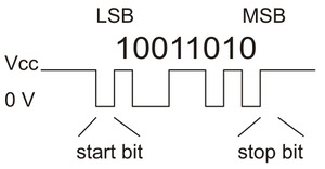 |
Diagram of a non-inverted TTL serial byte. |
|---|
The serial lines are high by default. The beginning of a transmitted byte is signaled with a single low start bit, followed by the bits of byte, least-significant bit (LSB) first. The byte is terminated by a stop bit, which is the line going high for at least one bit time.
Connecting a serial device to one Jrk
If you have not done so already, you should follow the instructions in Section 4.3 to configure and test your motor, and follow the instructions in the appropriate part of Section 5 to set up your desired feedback method. You should leave your Jrk’s input mode set to “Serial / I²C / USB” (the default). In the “Serial interface” box, you will need to change the serial mode to “UART, fixed baud rate” and specify your desired baud rate. Be sure to click “Apply settings”.
Next, connect your serial device’s GND (ground) pin to one of the Jrk’s GND pins.
If your serial device operates at 5 V, you can directly connect the device’s TX line to the Jrk’s RX line and connect the Jrk’s TX line to the device’s RX line. The connection to the Jrk’s TX line is only needed if you want to read data from the Jrk. These connections, and some other optional connections, are shown in the diagram below:
 |
Connecting a 5V microcontroller or other TTL serial device to the TTL serial interface of the Jrk G2. Dashed connections are optional. |
|---|
If your serial device operates at 3.3 V, then you might need additional circuitry to shift the voltage levels. You can try connecting the device’s TX line directly to the Jrk’s RX line; this will usually work, but the input signal on the RX pin must reach at least 4 V to be guaranteed to be read as high. If you want to read data from the Jrk, you will need to consider how to connect the Jrk’s TX line to your device’s RX line. If your device’s RX line is 5V tolerant, meaning that it can accept a 5 V output being applied directly to it, then you should be able to connect the Jrk’s TX line directly to your device’s RX line. If your device’s RX line is not 5V tolerant, you will need to a use a level shifter—a separate board or chip that can convert 5 V signals down to 3.3 V. A voltage divider made with two resistors would work too.
Whenever connecting devices, remember to wire the grounds together, and ensure that each device is properly powered. Unpowered devices with a TTL serial port can turn on or partially on, drawing power from the serial line, which means that extra care must be taken when turning power off and on to reset the devices.
Note: You must use an inverter and level shifter such as a MAX232 or a Pololu 23201a Serial Adapter if you want to interface an RS-232 device with the Jrk. Connecting an RS-232 device directly to the Jrk can permanently damage it.
If you are using an Arduino or Arduino-compatible board, you should now try running the SerialSetTarget example that comes with the Jrk G2 Arduino library. The library’s README has information about how to get started and which pins of the Arduino to use. If you are using a different kind of microcontroller board, you will need to find or write code to control the Jrk on your platform. If you are writing your own code, we recommend that you first learn how to send and receive serial bytes on your platform, and then use the SerialSetTarget example and the source code of the Jrk G2 library as a reference. You should also refer to the sections in this guide about the Jrk’s commands (Section 11) and serial protocol (Section 12).
If your connections and code are OK, you should now see your motor moving back and forth. If the motor is not moving, you should check all of your connections and solder joints. You should make sure that the Jrk and your device are configured to use the same baud rate. The Jrk uses 9600 bits per second by default. You should also check the “Status” tab of the Jrk G2 Configuration Utility to see if any errors are being reported.
The SerialSetTarget example only writes data to the Jrk, so it does not test your connection to the Jrk’s TX line. If you want to read data from the Jrk, you should now try the SerialGetFeedback example, which reads the feedback value from the Jrk. If you are using open-loop speed control (“Feedback mode” is “None”), you should change the getScaledFeedback command in that example to getPIDPeriodCount so you can see a number that is actually meaningful.
Optional connections
The Jrk’s 5V (out) pin provides access to the output of the Jrk’s 5V regulator, which also powers the Jrk’s microcontroller and the red and yellow LEDs. You can use the Jrk’s regulator to power your microcontroller or other serial device if the device does not draw too much current (see Section 7.8).
The VM pin provides access to the Jrk’s power supply after the reverse-voltage protection circuit, and this pin can be used to provide reverse-voltage-protected power to other components in the system if the Jrk supply voltage is within the operating range of those components. Note: this pin should not be used to supply more than 500 mA; higher-current connections should be made directly to the power supply. Unlike the 5V (out) pin described above, this is not a regulated, logic-level output.
The ERR pin of the Jrk is normally pulled low, but drives high to indicate when an error (other than the “Awaiting command” error bit) is stopping the motor. You can connect this line to an input on your microcontroller (assuming it is 5V tolerant) to quickly tell whether the Jrk is experiencing an error or not. Alternatively, you can query the Jrk’s serial interface to see if an error is happening, and which specific errors are happening. For more information about the ERR pin, see Section 7.7.
The RST pin of the Jrk is connected directly to the reset pin of the Jrk’s microcontroller and also has a 10 kΩ resistor pulling it up to 5 V. You can drive this pin low to perform a hard reset of the Jrk’s microcontroller and immediately turn off the motor, but this should generally not be necessary for typical applications. You should wait at least 10 ms after a reset before sending commands to the Jrk.
Connecting a serial device to multiple Jrks
The Jrk’s serial protocol is designed so that you can control multiple Jrks using a single TTL serial port. Before attempting to do this, however, we recommend that you first get your system working with just one Jrk as described above.
Next, make sure that the serial device and the Jrks all share a common ground, for example by connecting a GND pin from the device to a GND pin on each of the Jrks. Make sure that the TX pin on the serial device is connected to the RX pin of each Jrk (via a level shifter if needed).
If you attempt to run the SerialSetTarget example in this configuration, you should see each of your Jrk controllers moving. That example uses the Jrk’s Compact Protocol, which is only suitable for controlling one device. The Compact Protocol commands do not contain a device number, so every Jrk device that sees a Compact Protocol command will obey it. This is probably not what you want.
To allow independent control of multiple Jrks, you should use the Jrk G2 Configuration Utility to configure each Jrk to have a different device number. Then you should change your code to use the Pololu Protocol as described in Section 12. If you are using our Jrk G2 Arduino library, you can declare one object for each Jrk, and specify the device number of each Jrk, by writing code like this at the top of your sketch, which uses device numbers 11 and 12:
JrkG2Serial jrk1(jrkSerial, 11);
JrkG2Serial jrk2(JrkSerial, 12);
If you want to read data from multiple Jrks, you cannot simply connect all of the Jrk TX lines together, because when one of Jrks tries to drive its TX line low to send data, the TX lines from the other Jrks will still be driving the line high and will prevent the signal from going all the way to 0 V. Instead, you will need to connect an external AND gate. The TX line of each Jrk should be connected to an input line of the AND gate. The output of the AND gate should be connected to the RX line of your serial device (through a voltage divider or level shifter if necessary). The following diagram shows these connections along with optional connections of the ERR and RST pins:
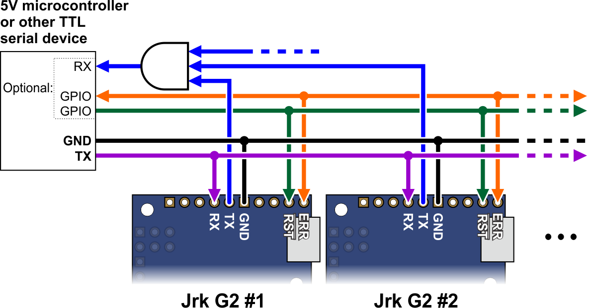 |
Wiring diagram for controlling multiple Jrk G2 modules from a single TTL serial source, such as a microcontroller. |
|---|
The ERR pins can all be safely connected together. In such a configuration, the line will be high if one or more Jrks has an error; otherwise, it will be low.
Using I²C instead of serial to read data from multiple Jrks does not require an AND gate (see Section 6.3).
The microcontroller shown in the diagram above can be a Jrk that is connected to a computer via USB. You would set the serial mode of that Jrk to “USB Chained” while leaving the serial modes of the other Jrks set to “UART”. The USB-connected Jrk would act as a USB-to-serial adapter while also listening for serial commands from the computer. You would be able to send serial commands to its USB Command Port in order to control all of the Jrks.
More information about the serial interface
This user’s guide has more information about the Jrk’s commands (Section 11) and serial protocol (Section 12).
6.3. Setting up I²C control
This section explains how to connect a microcontroller to the Jrk G2’s I²C interface so that you can send commands to control the Jrk G2. The Jrk G2 library for Arduino makes it particularly easy to control the Jrk from an Arduino or Arduino-compatible board such as an A-Star 32U4.
About the I²C interface
The SCL and SDA/AN pins of the Jrk provide its I²C interface. The pins are open drain outputs, meaning that they only drive low and they never drive high. Each pin has a 220 Ω series resistor protecting it from short circuits. By default, each pin is pulled up to 5 V by the Jrk’s microcontroller with a pull-up resistor that is typically around 40 kΩ. When the Jrk is reading the SCL or SDA pin as an input, any value over 2.1 V will be considered to be high.
Devices on the I²C bus have two roles: a master that initiates communication, and a slave that responds to requests from a master. The Jrk acts as the slave. The Jrk uses a feature of I²C called clock stretching, meaning that it holds the SCL line low to delay I²C communication while it is busy processing data from the master.
Connecting an I²C device to one Jrk
If you have not done so already, you should follow the instructions in Section 4.3 to configure and test your motor, and follow the instructions in the appropriate part of Section 5 to set up your desired feedback method. You should leave your Jrk’s input mode set to its default value of “Serial / I²C / USB” and leave the “Device number” set to its default value of 11. The “Device number” specifies the 7-bit address for the Jrk to use on the I²C bus.
Next, connect your device’s SCL pin to the Jrk’s SCL pin, and connect your device’s SDA pin to the Jrk’s SDA pin. You should also connect your device’s GND (ground) pin to one of the Jrk’s GND pins. These connections, and some other optional connections, are shown in the diagram below:
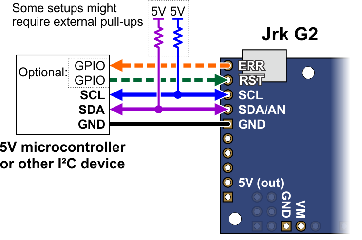 |
Connecting a 5V microcontroller or other I²C device to the I²C interface of the Jrk G2. Dashed connections are optional. |
|---|
Because the Jrk considers an input value of 2.1 V on SCL or SDA to be high, you can connect those pins directly to 3.3 V microcontrollers without needing a level shifter. If your microcontroller’s I²C interface is not 5V tolerant, it will usually still have a diode going from each I/O pin to its logic supply. These diodes clamp the voltage on the pins, preventing the Jrk’s pull-up resistors from pulling the pins too high. If you want to be extra safe and not rely on the clamping diodes, you can disable the Jrk’s pull-up resistors by going to the “Advanced” tab and checking “Disable I²C pull-ups”.
Depending on your setup, you might need to add pull-up resistors to the SCL and SDA lines of your I²C bus to ensure that the signals rise fast enough. The Jrk’s pull-up resistors are enabled by default, and many I²C master devices will have pull-ups too, but that might not be enough, especially if you want to use speeds faster than 100 kHz or have long wires. The I²C-bus specification and user manual (1MB pdf) has some information about picking pull-up resistors in the “Pull-up resistor sizing” section, and trying a value around 10 kΩ is generally a good starting point.
If you are using an Arduino or Arduino-compatible board, you should now try running the I2CSetTarget example that comes with the Jrk G2 Arduino library. If you are using a different kind of microcontroller board, you will need to find or write code to control the Jrk on your platform. If you are writing your own code, we recommend that you first learn how to use the I²C interface of your platform, and then use the I2CSetTarget example and the source code of the Jrk G2 library as a reference. You should also refer to the sections in this guide about the Jrk’s commands (Section 11) and I²C protocol (Section 13).
If your connections and code are OK, you should now see your motor moving back and forth. If the motor is not moving, you should check all of your connections and solder joints. You should check the “Status” tab of the Jrk Control Center to see if any errors are being reported. You can also try slowing down your I²C clock speed to something very slow like 1 kHz or 10 kHz. If slowing down the clock works, then the problem might be due to not having strong enough pull-up resistors on the SDA and SCL lines.
Optional connections
The Jrk’s 5V (out) pin provides access to the output of the Jrk’s 5V regulator, which also powers the Jrk’s microcontroller and the red and yellow LEDs. You can use the Jrk’s regulator to power your microcontroller or another device if the device does not draw too much current (see Section 7.8).
The VM pin provides access to the Jrk’s power supply after the reverse-voltage protection circuit, and this pin can be used to provide reverse-voltage-protected power to other components in the system if the Jrk supply voltage is within the operating range of those components. Note: this pin should not be used to supply more than 500 mA; higher-current connections should be made directly to the power supply. Unlike the 5V (out) pin described above, this is not a regulated, logic-level output.
The ERR pin of the Jrk is normally pulled low, but drives high to indicate when an error (other than the “Awaiting command” error bit) is stopping the motor. You can connect this line to an input on your microcontroller (assuming it is 5V tolerant) to quickly tell whether the Jrk is experiencing an error or not. Alternatively, you can query the Jrk’s serial interface to see if an error is happening, and which specific errors are happening. For more information about the ERR pin, see Section 7.7.
The RST pin of the Jrk is connected directly to the reset pin of the Jrk’s microcontroller and also has a 10 kΩ resistor pulling it up to 5 V. You can drive this pin low to perform a hard reset of the Jrk’s microcontroller and immediately turn off the motor, but this should generally not be necessary for typical applications. You should wait at least 10 ms after a reset before sending commands to the Jrk.
Controlling multiple Jrks with I²C
I²C is designed so that you can control multiple slave devices on a single bus. Before attempting to do this, however, we recommend that you first get your system working with just one Jrk as described above.
Next, make sure that the I²C master device and the Jrks all share a common ground, for example by connecting a GND pin from the I²C master device to a GND pin on each of the Jrks. Make sure that the SCL pins of all devices are connected and that the SDA pins of all devices are connected.
You should use the Jrk G2 Configuration Utility to configure each Jrk to have a different “Device number”, which specifies the 7-bit I²C address to use. Then you should change your code to use those addresses. If you are using our Jrk G2 Arduino library, you can declare one object for each Jrk by writing code like this at the top of your sketch, which uses addresses 11 and 12:
JrkG2I2C jrk1(11);
JrkG2I2C jrk2(12);
The following diagram shows the standard I²C connections described above along with optional connections of the ERR and RST pins:
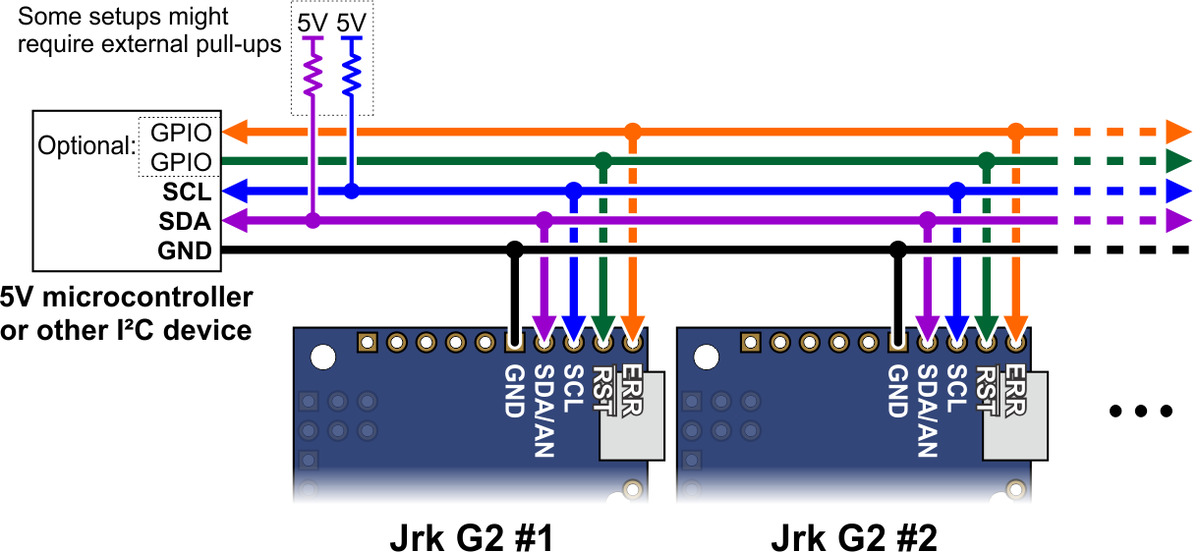 |
Wiring diagram for controlling multiple Jrk G2 modules from a single I²C source, such as a microcontroller. |
|---|
The ERR pins can all be safely connected together. In such a configuration, the line will be high if one or more Jrks has an error; otherwise, it will be low.
More information about the I²C interface
This user’s guide has more information about the Jrk’s commands (Section 11) and I²C protocol (Section 13).
6.4. Setting up analog control
This section explains how to set up the Jrk G2 to read an analog control input and calculate its “Target” variable from that. Please note that this is different from setting up analog feedback, which is documented in Section 5.2.
If you have not done so already, you should follow the instructions in Section 4.3 to configure and test your motor, and follow the instructions in the appropriate part of Section 5 to set up your desired feedback method.
The Jrk can read the analog voltage on its SDA/AN pin and set its “Input” variable to a value reflecting the voltage, where 0 corresponds to GND (0 V) and 4092 roughly corresponds to 5 V.
If you are using a potentiometer to make the analog control signal, you should connect the potentiometer’s wiper to SDA/AN and connect the other two ends to GND and SCL. In analog input mode, the SCL line is driven high (5 V) to power the potentiometer. Note that the SCL pin is protected by a 220 Ω series resistor, so it will not be damaged by accidental shorts to ground.
 |
Connecting an analog voltage control input to the Jrk G2. |
|---|
If you are using something other than a potentiometer to generate the analog control signal, make sure that the ground node of that device is connected to a GND pin of the Jrk, and that the signal from that device is connected to the SDA/AN pin. The Jrk can only accept signals between 0 V and 5 V with respect to GND; signals outside of this range could damage the Jrk.
Now connect the Jrk to your computer via USB. In the Jrk G2 Configuration Utility software, go to the “Input” tab and set the “Input mode” to “Analog voltage”. If you are powering an input potentiometer from the SCL pin, you should also check the “Detect disconnect with power pin (SCL)” checkbox. This causes the Jrk to drive SCL low periodically to help detect whether the input potentiometer has been disconnected. You should also go to the “Errors” tab and set the “Input invalid” and “Input disconnect” errors to enabled and latched, regardless of what kind of input you are using. Click “Apply settings”.
Go to the “Input” tab, and in the “Scaling” box, click “Input setup wizard…”. This wizard will help you measure the neutral, maximum, and minimum positions of your analog signal. When the wizard is finished, it will set seven of the input scaling parameters (input error maximum, input maximum, input neutral maximum, input neutral minimum, input minimum, input error minimum, and invert input direction) appropriately so that neutral analog signals get mapped to the target neutral value, the maximum analog value gets mapped to the target maximum, and the minimum analog value gets mapped to the target minimum.
The input setup wizard does not set the target maximum, target neutral, and target minimum values, so you will need to set them yourself:
- If you are using open-loop speed control (“Feedback mode” is “None”), you should probably set those values to 2648, 2048, and 1448, so that you can use the full range of your analog input. This assumes you also you want to drive your motor at full speed in both directions. If that is not the case, you can move the target maximum and/or target minimum values closer to 2048 to reduce the speed and use more of the range of your analog input.
- If you are using analog feedback, the default values of 4095, 2048, and 0, will generally be pretty good.
- If you are using frequency feedback (speed control), you will probably want to set those values to 2048 + F, 2048, and 2048 − F, where F corresponds to the maximum frequency (speed) you want to command the Jrk to obtain (see Section 5.3).
Click “Apply settings” to save these settings to the Jrk.
Now turn on motor power and click “Run motor” to start your system. As you move your input from end to the other, you should see your system moving through its full range of speeds or positions.
Finally, check the “Scaling degree” parameter. The default is “1 – Linear”. If you want finer control near the neutral point of your input and coarser control near the ends, you can change it to one of the higher settings.
For details about how the input scaling works, see Section 7.3.
6.5. Setting up RC control
This section explains how to set up the Jrk G2 to read a standard hobby RC pulse input and calculate its “Target” variable from that. Please note that this is different from setting up frequency feedback using pulse timing, which is documented in Section 5.3.
If you have not done so already, you should follow the instructions in Section 4.3 to configure and test your motor, and follow the instructions in the appropriate part of Section 5 to set up your desired feedback method.
The Jrk’s RC input accepts the same kind of signal that is used to control standard hobby RC servos, making it compatible with RC receivers. The signal should be low (0 V) by default, with regular 5 V pulses that last between 1 ms and 2 ms typically (though the Jrk can accept a wider range of roughly 0.2 ms to 2.7 ms). The Jrk can measure the RC signal and set the “Input” variable equal to the RC pulse width, in units of 2/3 µs.
With the system unpowered, connect your RC receiver to the Jrk’s GND, 5V, and RC pins.
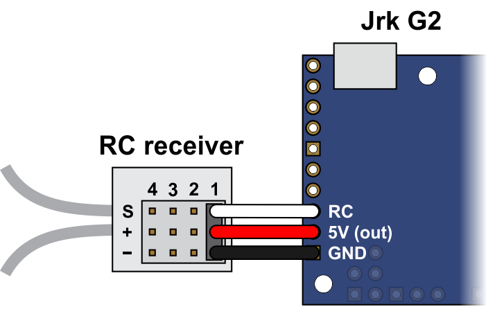 |
Connecting an RC receiver to the Jrk G2. |
|---|
In this configuration, the RC receiver will be powered by the Jrk’s 5 V regulator via the 5V output pin. If you want to power the receiver from another power source instead, you should not connect the Jrk’s 5V pin to it as doing so would short the two sources together and could damage the Jrk or receiver.
If the Jrk gets reset when you plug in your RC receiver, it might be because the in-rush current of the receiver is too much for the Jrk’s 5V line and causes its voltage to drop temporarily. As general good engineering practice, we recommend making and breaking electrical connections only while your devices are powered off.
Now connect the Jrk to your computer via USB. In the Jrk G2 Configuration Utility software, go to the “Input” tab and set the “Input mode” to “RC”. You should also go to the “Errors” tab and set the “Input invalid” and “Input disconnect” errors to enabled. Click “Apply settings”.
Go to the “Input” tab, and in the “Scaling” box, click “Input setup wizard…”. This wizard will help you measure the neutral, maximum, and minimum positions of your RC signal. When the wizard is finished, it will set seven of the input scaling parameters (input error maximum, input maximum, input neutral maximum, input neutral minimum, input minimum, input error minimum, and invert input direction) appropriately so that neutral RC signals get mapped to the target neutral value, the maximum RC signal gets mapped to the target maximum, and the minimum RC signal gets mapped to the target minimum.
The input setup wizard does not set the target maximum, target neutral, and target minimum values, so you will need to set them yourself:
- If you are using open-loop speed control (“Feedback mode” is “None”), you should probably set those values to 2648, 2048, and 1448, so that you can use the full range of your RC input. This assumes you also you want to drive your motor at full speed in both directions. If that is not the case, you can move the target maximum and/or target minimum values closer to 2048 to reduce the speed and use more of the range of your RC input.
- If you are using analog feedback, the default values of 4095, 2048, and 0, will generally be pretty good.
- If you are using frequency feedback (speed control), you will probably want to set those values to 2048 + F, 2048, and 2048 − F, where F corresponds to the maximum frequency (speed) you want to command the Jrk to obtain (see Section 5.3).
Click “Apply settings” to save these settings to the Jrk.
Now turn on motor power and click “Run motor” to start your system. As you move your input from end to the other, you should see your system moving through its full range of speeds or positions.
Finally, check the “Scaling degree” parameter. The default is “1 – Linear”. If you want finer control near the neutral point of your input and coarser control near the ends, you can change it to one of the higher settings.
For details about how the input scaling works, see Section 7.3.
7. Details
7.1. LED feedback
The Jrk G2 motor controller has three LEDs to indicate its status.
The green LED indicates the USB status of the device. When you connect the Jrk to a computer via a USB cable, the green LED will start blinking slowly. The blinking continues until the Jrk gets a particular message from the computer that indicates that the Jrk is recognized. After the Jrk gets that message, the green LED will be on, but it will flicker briefly when there is USB activity. During suspend mode (i.e. when the Jrk is only powered from USB and the computer has gone to sleep), the green LED will blink very briefly once per second.
The red LED turns on if and only if there is an error (other than the Awaiting Command error bit) stopping the motor. This LED is tied to the ERR pin. For more information about error handling, see Section 7.7.
The yellow LED indicates the status of the motor and also gives some information about what errors, if any, are happening:
- If an error (other than the “Awaiting command” error bit) is stopping the motor, the yellow LED will be off.
- If the Awaiting Command Error bit is set or the Jrk is in open-loop speed control mode and the duty cycle is zero, the yellow LED will blink slowly (once per second).
- If the motor is on and has reached the desired state, the yellow LED will be on solid.
- For analog and frequency feedback modes, this means that the target is within 20 of the scaled feedback.
- For open-loop speed control mode, this means that the duty cycle equals the duty cycle target.
- If the motor is on and has not reached its desired state, the yellow LED will flash quickly (16 times per second).
The information expressed by the Jrk’s LEDs can also be seen by connecting the Jrk to a computer via USB, running the Jrk G2 Configuration Utility, and looking in the Status and Errors tabs.
Startup blinking
When the Jrk starts running, it tries to detect if it was reset by some special condition. If it experiences a brown-out reset, watchdog timer reset, software reset, stack overflow, or stack underflow, the Jrk will blink its yellow LED eight times over a one second period while the red LED is on at startup. While it is doing this blinking, the Jrk will not accept any commands, read any inputs, or run the motor. You can see the cause of the last reset in the Jrk G2 Configuration Utility software’s “Last reset” field.
Bootloader mode
In bootloader mode, which is used for updating the firmware of the Jrk and should only rarely be needed, the LEDs behave differently. The green LED still indicates the USB status, but it is different: after the bootloader gets a particular message from the computer that indicates that the bootloader is recognized, the green LED will start doing a double blinking pattern every 1.4 seconds. The yellow LED will usually be on solid, but it will blink quickly whenever a USB command is received. The red LED will be on if and only if there is no firmware currently loaded on the device.
7.2. Graph window
The graph window of the Jrk G2 Configuration Utility shows a real-time graph of several important variables from the Jrk. You can open the graph window by selecting “Graph” from the “Windows” menu, or by clicking on the graph in the “Status” tab.
While the graph window is open, the graph is displayed there instead of in the Status tab. The controls in the graph window allow you to select which variables to plot and configure how they are plotted. When you close the graph window, the graph moves back to the Status tab.
Variables plotted on the graph
Most of the variables that can be plotted in the graph are documented in Section 10, with these exceptions:
- The “Error” variable is the “Scaled feedback” minus the “Target”. This is the same as the error variable used by the PID calculation (Section 7.5), except it does not account for the feedback wraparound setting.
- The “Raw current (mV)” variable is the measured voltage on the Jrk’s internal current sense line (see Section 7.6).
- The “Current” variable is the Jrk’s estimate of the motor current (see Section 7.6).
- The “Current chopping” variable shown in the graph is 1 if hardware current chopping has happened since the last time the graph was updated, and 0 otherwise. When “Current chopping” is 1, it means the motor exceeded the configured hard current limit. This variable is derived from the Jrk’s “Current chopping occurrence count” variable. Note that this variable is only valid for the Jrk G2 18v19, 24v13, 18v27, and 24v21. The Jrk G2 21v3 cannot detect when current chopping occurs.
The graph window is updated every 50 ms, so if the Jrk’s PID period is faster than that (which it is by default), then the graph will not be able to show readings from every PID period.
Choosing which variables are shown
By default, only the “Target” and “Scaled feedback” variables are plotted. You can add more variables to the graph by checking the corresponding checkboxes, and you can hide variables by unchecking the corresponding checkboxes.
The “Show all/none” button show all the variables by default, but if all the variables are shown already then it will hide all of them.
Changing plot colors
To change the color of a plot, right-click on the corresponding checkbox and select “Change color”. You can switch back to the default color by selecting “Reset color” from the that menu. You can change all the plots to use their default colors by selecting “Reset all colors” in the “Options” menu in the upper left corner of the graph window.
In the “Options” menu, you can select “Use dark theme” to change the graph’s background to black and use a different set of colors for plotting variables. To get back to light mode, select “Use default theme” in the “Options” menu. The graph keeps track of the plot colors for dark mode separately from the colors you choose in light mode, so any color changes you make while one theme is selected will not affect the other theme.
Entering the plot position and scale
The graph window allows you to set the position and scale of each plotted variable independently, much like an oscilloscope.
The scale is the number of counts of the variable value that correspond to one vertical division of the graph. The vertical divisions are marked by the heavier horizontal lines on the graph; there are ten divisions total. The default scale of many of the variables is 819; this means that one division corresponds to 819 counts, and five divisions corresponds to 4095 counts.
The position specifies where the X axis of the plot is located, in units of the variable value, relative to the vertical midpoint of the graph. Another way to think about it is that zero minus the position is equal to the variable value at the vertical midpoint of the graph. For example, if the scale is 100 and the position is 200, then the X axis of the plot will be located two divisions above the vertical midpoint of the graph, and any data points plotted at the vertical midpoint of the graph indicate a variable value of −200. The X axis of a plot is the horizontal line at which the variable value is zero.
You can set the position and the scale directly using the numeric inputs on the right side of the graph. After selecting a numeric input, you can either type in a number or use the arrow keys to go up and down in steps. You can press PageUp or PageDown to go up or down 10 steps at a time.
You can switch back to the default position and scale for a plot by right-clicking on the corresponding checkbox and selecting “Reset position and scale”. You can change all the plots to use their default positions and scales by selecting “Reset all positions and scales” from the “Options” menu.
The location of each plot’s X axis is marked with a right-pointing arrowhead on the left side of the graph. Similar arrows are also drawn on the top and bottom sides of the graph if any of plotted variable values have overflowed the top or bottom side of the graph and thus are not visible. If you see arrows on the top or bottom, it means there is data off the screen that you cannot see, and you might consider adjusting the position or scale to make that data visible.
Setting the plot position and scale with the mouse
As an alternative to entering the position scale using the numeric inputs, it is possible to select a plot and then use the mouse to set the position and scale.
First, to select a plot, you need to do one of the following:
- Right-click on the corresponding checkbox and select “Select”. This is the most reliable way to select a plot.
- Adjust the position or scale of a plot using the numeric inputs. This automatically selects the plot as a side effect.
- Click near any of the plot’s data points or arrowheads to select it. If multiple plots are visible and overlapping, this does not always work reliably. If you click close to two different plots, the one that is closest to your mouse cursor will be selected.
When a plot is selected, labels for its position and scale will appear on the left side of the screen near its X axis arrowhead, all of its arrowheads will be slightly bigger than usual, and the plotted data line will be slightly thicker. You can look for any of these visual cues in order to make sure you have selected the right plot.
Once you have selected a plot, you can adjust its position by holding the Shift key and dragging upwards or downwards on the graph surface. More specifically: put your mouse cursor in the graph area, start holding down the shift key, start holding down the left mouse button, move the mouse up or down, and release the mouse button. You can release the shift key any time after you start holding down the mouse button.
You can also drag a plot without using the shift key, but your mouse will have to be pointing to that plot or one of its arrowheads when you start dragging, and if there is another plot nearby you might accidentally end up dragging that plot instead. Holding down the shift key allows you to drag the selected plot from any part of the graph.
While a plot is selected, you can also zoom in and out (affecting both the position and the scale) by using your mouse wheel while the cursor is over the graph area. When you do this, the vertical position of your mouse matters: the zooming is centered on the horizontal line going through your cursor, meaning that any data points on that horizontal line will not move (or move very little) as you zoom in and out. If you’re zooming in, you should probably put your cursor over the data you want to see while you are zooming in.
You can also use the mouse wheel on the “Scale” and “Position” numeric inputs, as an alternative to using the arrow keys.
Time settings
By default, the graph window shows the last 10 seconds of data from the Jrk. The right side of the graph corresponds to the most recent data, and the left side of the graph corresponds to data that is 10 seconds old. You can change the timespan to be anything from 1 to 90 seconds by entering the desired number of seconds into the numeric input labeled “Time (ms)”.
You can stop the graph from moving by clicking the “Pause” button, and then restart it later by clicking the “Run” button.
The software keeps track of the last 90 seconds of data for all variables, so if something interesting happens and then the data for it scrolls off the graph, just press the Pause button quickly and set the time span to 90 seconds to see the what happened. You can change any of the graph settings while the graph is paused.
Saving and loading graph settings
In the “Options” menu, the “Save graph settings…” and “Load graph settings…” commands allow you to save your graph settings to a text file and load them back later. These settings are generally lost whenever you restart the Jrk configuration utility, so if you have spent a lot of time adjusting the appearance of your graph then you might find it useful to save those settings for later.
7.3. Analog/RC input handling
This section documents the details of how the Jrk G2 reads its analog and RC control inputs in order to set the “Input” variable, and how it scales those inputs in order to set the “Target” variable.
Analog input on SDA/AN
When the Jrk’s “Input mode” is set to “Analog voltage” or the “Always configure SDA/AN for analog input” option is enabled, the Jrk disables its I²C interface and uses the SDA/AN pin as an analog input. Once per PID period, the Jrk takes a configurable number of readings of the SDA/AN pin. The “Analog samples” option in the “Input” tab controls how many readings to take. The Jrk has a 10-bit analog-to-digital converter (ADC), so each reading is a number between 0 and 1023. These readings are added together and bit-shifted appropriately to get a number between 0 and 65,472 which is stored in the “Analog reading SDA” variable, which can be read from the Jrk over USB, serial, or I²C.
If the “Input mode” is set to “Analog voltage” then the Jrk will set its “Input” variable to be equal to the “Analog reading SDA” variable divided by 16. An input value of 0 roughly corresponds to a voltage of 0 V, while an input value of 4092 roughly corresponds to the voltage on the Jrk’s 5V pin.
The “Detect disconnect with power pin (SCL)” option, which is only available when the “Input mode” is set to “Analog voltage”, causes the Jrk to drive the SCL pin low once per PID period after measuring SDA/AN. If the voltage on the SDA/AN pin does not drop by at least a factor of two while SCL is low, then the Jrk reports an “Input disconnect” error (if that error is enabled). The SCL pin drives high at other times.
By default, the SDA/AN input does not have a pull-up resistor, but you can enable one by checking the “Enable pull-up for analog input on SDA/AN” option in the “Advanced” tab.
Pulse measurement on the RC pin
The Jrk measures the width of RC pulses on its RC input pin. The signal on the RC pin should look like the waveform shown below:
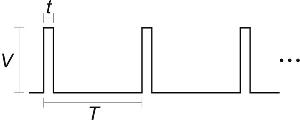 |
The signal should be low (0 V) normally and have periodic pulses with an amplitude (V) of at least 2 V. The width of the pulses (t) should be between 200 µs and 2700 µs. The period of the signal (T), should be at most 100 ms, and the there is no particular lower limit. When the Jrk has received three good pulses in a row, it writes the width of the latest pulse to the “RC pulse width” variable in units of 1/12 µs. The “RC pulse width” variable can be read from the Jrk over USB, serial, or I²C.
If the Jrk goes more than 100 ms without receiving a good pulse, it will change the “RC pulse width” variable to 0 to indicate that the RC signal has been lost. Similarly, if the Jrk goes more than 500 ms without receiving three good pulses in a row, it will change the “RC pulse width” variable to 0.
If the “Input mode” is set to “RC pulse width” then the Jrk will set its “Input” variable to be equal to the “RC pulse width” variable divided by 8, so the “Input” variable will have units of 2/3 µs. The Jrk will also report an “Input invalid” error if that error is enabled and the RC signal has been lost.
RC and analog input scaling
The settings in the “Scaling” box of the “Input” tab determine how the “Input” variable is scaled to compute the “Target” variable. The graphs below illustrate this mapping:
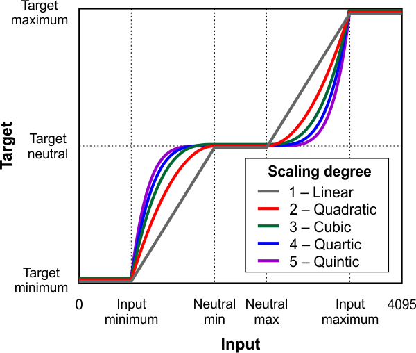 |
This graph shows how the RC/analog input of the Jrk G2 is scaled to produce a target position or target velocity (input direction not inverted). |
|---|
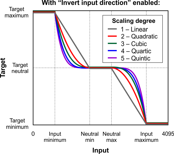 |
This graph shows how the RC/analog input of the Jrk G2 is scaled to produce a target position or target velocity (input direction inverted). |
|---|
When the “Invert input direction” box is not checked, the input values are mapped to output/target values according to these rules:
- Any input value greater than the input maximum gets mapped to the target maximum.
- Any input value between the input neutral max and the input maximum gets mapped to a number between the target neutral value and the target maximum.
- Any input value between the input neutral min and input neutral max gets mapped to the target neutral value.
- Any input value between the input minimum and the input neutral min gets mapped to a number between the target minimum and target neutral value.
- Any input value less than the input minimum gets mapped to the target minimum.
When the “Invert input direction” checkbox is checked, it changes the scaling so that higher input values correspond to lower target values. You can think of it as simply switching the target maximum and target minimum in the rules above.
The “Degree” of the scaling can be set to “1 – Linear”, “2 – Quadratic”, “3 – Cubic”, “4 – Quartic”, or “5 – Quintic”. With the default setting of “1- Linear”, the scaling function is linear. If you choose a higher scaling degree, then the Jrk uses a higher-degree polynomial function, which can give you finer control when the input is closer to its neutral position. With linear scaling, if the input is one quarter (1/4) of the way from the input neutral max to the input maximum, the target will be one quarter (1/4) of the way from the target neutral value to the target maximum. With quadratic scaling, the target would be one sixteenth (1/16) of the way from the target neutral value to the target maximum. With cubic scaling, the ratio would be 1/64, and so on.
The “Input” and “Target” variables are always between 0 and 4095, and each input scaling parameter must also be between 0 and 4095.
Input error min/max
The “Error max” and “Error min” settings in the “Scaling” box in the “Input” tab specify the allowed range of the input. If the “Input disconnect” error is enabled, and the “Input mode” is “Analog voltage” or “RC”, and the “Input” variable outside of the range specified by those limits, then the Jrk will report an “Input disconnect” error. With the default values of these settings (0 and 4095), the input value should never be out of range.
7.4. Analog/frequency feedback handling
This section documents the details of how the Jrk G2 reads its analog and frequency feedback inputs in order to set the “Feedback” variable, and how it scales those inputs in order to set the “Scaled feedback” variable.
Analog feedback on FBA
When the Jrk’s “Feedback mode” is set to “Analog voltage” or the “Always configure FBA for analog input” option is enabled, the Jrk uses the FBA pin as an analog input. Once per PID period, the Jrk takes a configurable number of readings of the FBA pin. The “Analog samples” option in the “Feedback” tab controls how many readings to take. The Jrk has a 10-bit analog-to-digital converter (ADC), so each reading is a number between 0 and 1023. These readings are added together and bit-shifted appropriately to get a number between 0 and 65,472 which is stored in the “Analog reading FBA” variable, which can be read from the Jrk over USB, serial, or I²C.
If the “Feedback mode” is set to “Analog voltage” then the Jrk will set its “Feedback” variable to be equal to the “Analog reading FBA” variable divided by 16. A feedback value of 0 roughly corresponds to a voltage of 0 V, while a feedback value of 4092 roughly corresponds to the voltage on the Jrk’s 5V pin.
The “Detect disconnect with power pin (AUX)” option, which is only available when the “Feedback mode” is set to “Analog voltage”, causes the Jrk to drive the AUX pin low once per PID period after measuring FBA. If the voltage on the FBA pin does not drop by at least a factor of two while AUX is low, then the Jrk reports a “Feedback disconnect” error (if that error is enabled). The AUX pin drives high at other times.
The “Wraparound” option, which is only available when the “Feedback mode” is set to “Analog voltage”, specifies that the Jrk should consider a scaled feedback value of 4095 to be adjacent to a scaled feedback value of 0 when calculating the “Error” in the PID algorithm. This is useful for systems where the motor can rotate continuously over a full circle, and you want the system to take the shortest path between any two points on the circle.
The FBA pin does not have a pull-up resistor.
Frequency feedback on FBT
The Jrk measures the frequency of digital pulses on the FBT pin. The voltage on FBT should be between 0 V and 5 V with respect to GND. FBT is read as a digital input, and the signal must be below 1 V to be guaranteed to read as low and above 4 V to be guaranteed to be read as high. The FBT pin is pulled up to 5 V by an on-board 100kΩ resistor. There are two frequency measurement methods: pulse counting and pulse timing.
In pulse counting mode, the Jrk will count the number of rising edges on the FBT pin each PID period (which is 10 ms by default). At the end of each PID period, it will set the “FBT reading” variable to the number of rising edges that occurred during that PID period, assuming that the “Pulse samples” setting has its default value of 1. If the “Pulse samples” setting is more than 1, the Jrk will set the FBT reading to the number of rising edges from the last several PID periods, where the number of PID periods is specified by the “Pulse samples” setting. The FBT reading will then be divided by the value of the “Frequency divider” setting to obtain a frequency measurement that can be used to set the “Feedback” variable as described below.
In pulse timing mode, the Jrk will measure the width (duration) of pulses on the FBT pin. The “Pulse timing polarity” option controls whether it measures high pulses (“Active high”) or low pulses (“Active low”). The pulse width is measured as a number between 0 and 65535, in units of pulse timing clock ticks (one divided by the pulse timing clock frequency). The pulse timing clock can be set to wide range of frequencies from 1.5 MHz to 48 MHz. The “Pulse samples” setting specifies how many pulse widths to average together. The “Pulse timing timeout” setting specifies how long to wait before the Jrk starts recording pulses of maximum width (65535 ticks). (This is what allows the frequency measurement to decrease to its lowest possible value when the motor stops.) The Jrk sets the “FBT reading” variable to the average pulse width. A frequency measurement is obtained by computing 0x4000000 (2 raised to the power of 26) divided by the pulse width, and the frequency measurement is divided by the value of the “Frequency divider” setting before it is used to set the “Feedback” variable as described below.
After the Jrk has obtained a frequency measurement using either the pulse counting or pulse timing method, if the “Feedback mode” is “Frequency”, the Jrk will set the “Feedback” variable to 2048 plus or minus the frequency measurement, restricted to be between 0 and 4095. It will use “plus” if the “Target” variable (which specifies the desired speed) is 2048 or more, and it will use “minus” otherwise.
Feedback scaling
The settings in the “Scaling” box of the “Feedback” tab determine how the “Feedback” variable is scaled to compute the “Scaled feedback” variable. The graph below illustrates this mapping:
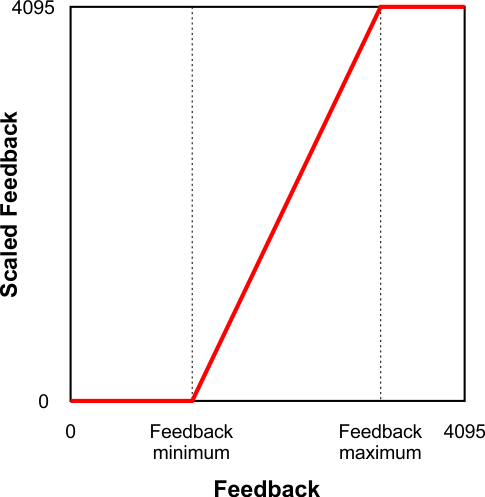 |
This graph shows how the Jrk G2 converts Feedback to Scaled Feedback. |
|---|
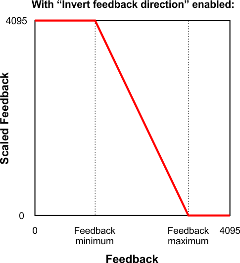 |
This graph shows how the Jrk G2 converts Feedback to Scaled Feedback (with feedback direction inverted). |
|---|
When the “Invert feedback direction” box is not checked, the feedback values are scaled according to these rules:
- Any feedback value greater than the maximum gets scaled to 4095.
- Any feedback value between the minimum and maximum gets scaled to a number between 0 and 4095 (with 0 corresponding to the minimum).
- Any feedback value less than the minimum gets scaled to 0.
When the “Invert feedback direction” checkbox is checked, it changes the scaling so that higher feedback values correspond to lower scaled feedback values. You can think of it as simply switching 0 and 4095 in the rules above.
Feedback error min/max
The “Error max” and “Error min” settings in the “Scaling” box in the “Feedback” tab specify the allowed range of the feedback. If the “Feedback disconnect” error is enabled, and the “Feedback mode” is “Analog voltage” or “Frequency”, and the “Feedback” variable outside of the range specified by those limits, then the Jrk will report a “Feedback disconnect” error. With the default values of these settings (0 and 4095), the feedback value should never be out of range.
7.5. PID calculation
When feedback is enabled, the Jrk G2 performs a PID calculation once per PID period to determine its “Duty cycle target” variable. This section explains the details of that calculation and the settings that affect it.
When the system is configured properly, the PID calculation should generally result in the “Scaled feedback” variable (which represents the position or speed of the system’s output) moving towards the “Target” variable (which represents the commanded position or speed). The first step of the PID calculation is to calculate the error by subtracting the target from scaled feedback (error = scaled feedback − target).
If the “Feedback mode” is “Analog voltage” and the “Wraparound” feature in the “Feedback” tab is enabled, the Jrk will add or subtract 4096 from the error if necessary in order to get it into the −2048 to +2048 range. The error can normally be any number between −4095 and 4095.
Then, the three terms that give the PID algorithm its name are calculated:
- The proportional term is proportional to the error. The Jrk calculates this term by multiplying the error by the proportional coefficient.
- The integral term is proportional to the accumulated sum of errors over time. The Jrk calculates this term by multiplying the integral variable (described below) by the integral coefficient.
- The derivative term is proportional to the change in the error relative to the previous PID period. The Jrk calculates this term by first calculating the error minus the error from the previous PID period, and then multiplying by the derivative coefficient.
The Jrk sets the “Duty cycle target” equal to zero minus the sum of these three terms. The subtraction is what causes the Jrk to move the motor in the direction that counteracts the error instead of amplifying it. A duty cycle target of 600 or more corresponds to 100% duty cycle in the forward direction, while a value of −600 corresponds to 100% duty cycle in the reverse direction, and a value of 0 corresponds to 0% duty cycle or off.
PID coefficients
Each of the PID coefficients is specified as an integer value between 0 and 1023 divided by a power of two from 20 (1) to 218 (262,144). The coefficients are 0 by default, and can have values from 0.0000038 to 1023. Any value above 0.0003815 can be approximated within 0.5%. To get the closest approximation to a desired value, type the number into the box after the equal sign in the “PID” tab, and the software will compute the best possible numerator and denominator.
The PID coefficients are normally configured ahead of time using the configuration utility software, but you can also use the Jrk G2’s “Set RAM settings” command to change them (and other settings) on the fly over serial, I²C, or USB (see Section 11).
PID period
The “PID period” setting sets the rate at which the Jrk runs through all of its calculations. Note that a higher PID period will result in a more slowly changing integral and a higher derivative, so that the two corresponding PID coefficients might need to be adjusted whenever the PID period is changed. The Jrk still respects the PID period setting even if feedback is disabled: the Jrk will only calculate its main input and update the motor speed once per PID period.
Integral calculation
Each PID period, the Jrk adds the error divided by the “Integral divider” setting to the “Integral” variable. The Jrk stores the integral internally with higher precision in order to avoid the accumulation of rounding errors due to the division. For example, if the error is consistently 1 and the integral divider is 8, the integral variable will increase by 1 every 8 PID periods.
The absolute value of the integral is not allowed to exceed the “Integral limit” setting, which defaults to 1000 but can be has high as 32,767.
The integral variable initially starts at zero, and it is also reset to zero whenever there are errors stopping the motor, whenever the “Force duty cycle” or “Force duty cycle target” commands are in effect, whenever the “Feedback dead zone” feature is in effect, and whenever feedback is disabled. If the “Reset integral when proportional term exceeds max duty cycle” setting is enabled, the integral is also reset to zero whenever the proportional term goes outside of the −600 to +600 range.
Feedback dead zone
The “Feedback dead zone” option sets the duty cycle target to zero and resets the integral whenever the magnitude of the error is smaller than the feedback dead zone amount. This is useful for preventing the motor from driving when the target is very close to the scaled feedback. The feedback dead zone uses hysteresis to keep the system from simply riding the edge of the dead zone; once in the dead zone, the duty cycle and integral will remain zero until the magnitude of the error exceeds twice this value.
7.6. Motor settings
The Jrk’s motor settings consist of parameters that determine how its duty cycle target is converted to a duty cycle and how the duty cycle corresponds to motor outputs, together with parameters that control its current sensing and limiting behavior. These settings can be configured on the Motor tab of the Jrk G2 Configuration Utility.
PWM frequency
The Jrk is capable of both 20 kHz and 5 kHz PWM, selectable with the “PWM frequency” setting.
The 20 kHz PWM frequency is ultrasonic and can thus eliminate audible PWM-induced motor humming, which makes this frequency desirable for typical applications.
However, a higher PWM frequency means greater power loss due to switching (producing more heat), which could make a 5 kHz PWM frequency a better choice for certain applications.
Additionally, the 5 kHz PWM frequency allows for slightly finer control at duty cycles approaching 0%. This is because PWM control pulses that are shorter than a certain time (about 4 µs for the Jrk G2 21v3 and 0.5 µs for the Jrk G2 18v19, 24v13, 18v27, and 24v21) have no effect on the output voltage.
Invert motor direction
The Jrk’s PWM duty cycle has a range of −600 to 600, where −600 is full reverse and 600 is full forward. In analog feedback mode, “forward” and “reverse” should be consistent with the scaled feedback values, so that when the duty cycle is positive, the motor spins in a direction that increases the scaled feedback. By default, full forward (+600) means motor output OUTA = VIN and OUTB = 0 V, while full reverse (−600) means OUTA = 0 V and OUTB = VIN. When checked, the “Invert motor direction” option switches these definitions so that full forward (+600) means OUTA = 0 V and OUTB = VIN, while full reverse (−600) means OUTA = VIN and OUTB = 0 V.
The feedback setup wizard can help you detect whether the motor direction needs to be inverted. It can be started by clicking the “Feedback setup wizard…” button next to the “Invert motor direction” checkbox when the feedback mode is analog. (This wizard can also be started from the Feedback tab.)
Motion parameters
Various limits may be applied to the duty cycle, each of which can be configured separately for forward (positive duty cycle) and reverse (negative duty cycle) if the “Asymmetric” option is checked:
“Max. duty cycle” limits the duty cycle itself.
“Max. acceleration” limits the amount that the duty cycle can increase in magnitude in a single PID period. For example, if there is a forward acceleration limit of 10, and the current duty cycle is 300, then the duty cycle in the next PID period can increase to no higher than 310.
“Max. deceleration” limits the amount that the duty cycle can decrease in magnitude in a single PID period. For example, if there is a forward deceleration limit of 10, and the current duty cycle is 300, then the duty cycle in the next PID period can decrease to no lower than 290.
“Brake duration” is a feature that is most useful for large motors with high-inertia loads used with frequency feedback or speed control mode (no feedback). If this option is used, the Jrk will automatically keep the motor at a duty cycle of 0 for the specified time when switching directions, after decelerating to 0 from the old direction but before beginning to accelerate in the new direction. (Note that if the “When motor is off” setting is set to “Coast”, the motor will coast instead of braking during this period.) The “forward” setting refers to switching from forward to reverse, and the “reverse” setting refers to switching from reverse to forward.
“Max. duty cycle while feedback is out of range” is an option to limit possible damage to systems by reducing the maximum duty cycle whenever the feedback value is beyond the absolute minimum and maximum values. This can be used, for example, to slowly bring a system back into its valid range of operation when it is dangerously near a mechanical limit. The “Feedback disconnect” error should be disabled when this option is used.
The “When motor is off” setting controls what the Jrk does with its motor outputs when the duty cycle is zero. There are two options: brake (OUTA and OUTB both connected to GND) or coast (OUTA and OUTB floating). With a non-zero duty cycle, the Jrk G2 PWMs the motor outputs between driving and braking.
You can familiarize yourself with motor coasting and braking using nothing more than a motor. First, with your motor disconnected from anything, try rotating the output shaft and note how easily it turns. Then hold the two motor leads together and try rotating the output shaft again. You should notice significantly more turning resistance while the leads are shorted together.
Current limiting and sensing
The motor driver circuit on the Jrk G2 allows it to monitor and limit the motor current. The measured current is reported on the Status tab of the configuration utility, and two different types of limits can be set on the Motor tab.
“Hard current limit" sets the hardware current limit for the Jrk’s motor driver circuit; when the motor current exceeds this value, the driver will actively limit it with current chopping. Hardware current limiting is performed entirely by the motor driver circuit, which means it can react quickly to current spikes (within a few microseconds) and is not dependent on the control loop running on the Jrk’s microcontroller. This setting is only available for the Jrk G2 18v19, 24v13, 18v27, and 24v21. The Jrk G2 21v3 has hardware current limiting with a fixed threshold of approximately 6.5 A, but the threshold decreases to 2.5 A when the motor driver temperature rises above approximately 160°C.
“Soft current limit" sets the motor current threshold for the “Soft overcurrent” error. If the Jrk’s motor current measurement exceeds this value, and the “Soft overcurrent” error is enabled, then the Jrk will set the corresponding error flag. See Section 7.7 for more information about error handling.
“Soft current regulation level" sets the target current level for software current regulation. If this setting is non-zero, then each PID period, the Jrk firmware will limit the duty cycle in an attempt to keep the measured current below this level. This feature generally works better when combined with acceleration and deceleration limits to help prevent rapid variations in duty cycle. This feature is only available on the Jrk G2 21v3, which does not have configurable hardware current limiting.
Note that the current limits are not precise thresholds: it is not unusual for the actual currents to be 20% off from the reported values, and currents near the lower end of each Jrk’s current capability are measured and limited less accurately. In addition, electrically noisy motors can cause the current measurement to be correspondingly unstable and inaccurate.
“Current samples” is the number of analog readings that the Jrk will perform and average together during each PID period in order to measure the current. A larger number of samples will tend to smooth out noise and current spikes better, but it takes more time and limits how fast the Jrk’s PID period can be.
“Hard overcurrent threshold” is the number of PID periods in which the motor current must be hardware-limited before the Jrk will report a “Hard overcurrent” error (if enabled). The default is 1, which means the Jrk will report an error after any detected occurrence of hardware current limiting, but you can raise this threshold to make the Jrk ignore shorter current spikes but still generate an error on longer ones. This setting is only available on the Jrk G2 18v19, 24v13, 18v27, and 24v21. The Jrk G2 21v3 cannot detect when hardware current-limiting occurs.
Current measurement on the Jrk G2 18v19, 24v13, 18v27, and 24v21
A high-power Jrk G2 (18v19, 24v13, 18v27, or 24v21) obtains a raw current sense measurement from the motor driver in the form of an analog voltage, which can be seen as the “Raw current” variable on the Status tab of the configuration utility and typically has an offset of about 50 mV when VIN is present, though the offset can vary widely from unit to unit. The Jrk converts this value into a current in units of milliamps with the following formulas (where the raw current sense measurement is Vraw and the reported current is I):
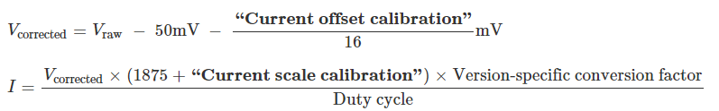 |
The two calibration settings adjust the results of this conversion: increasing the “Current offset calibration” shifts the reported current lower, and increasing the “Current scale calibration” scales the reported current larger.
If the Jrk reports extremely high, inaccurate currents while the motor is driving at a low duty cycle, it might be due to the analog current sense signal from the motor driver having an offset higher than the typical 50 mV offset. You can make the current readings more accurate at low duty cycles by setting the “Current offset calibration” setting properly.
Although setting the current limits appropriately can help protect the Jrk, your motor, and the rest of your system, please keep in mind that an over-temperature or over-current condition can still cause permanent damage; the higher-power Jrk G2 boards (18v19, 24v13, 18v27, and 24v21) do not have an over-temperature shut-off. (A motor driver error can indicate an over-temperature fault, but the higher-power Jrk G2s do not directly measure the temperature of the MOSFETs, which are usually the first components to overheat.)
Current measurement on the Jrk G2 21v3
The Jrk G2 21v3 obtains a raw current sense measurement from the motor driver in the form of an analog voltage, which be seen as the “Raw current” variable in the Status tab of the configuration utility. The Jrk converts this value into a current in units of milliamps with the following formulas (where the raw current sense measurement is Vraw and the reported current is I):
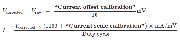 |
The two calibration settings adjust the results of this conversion: increasing the “Current offset calibration” shifts the reported current lower, and increasing the “Current scale calibration” scales the reported current larger.
7.7. Error handling
This section documents how the Jrk G2 handles error conditions that can stop the motor.
Error variables and commands
The Jrk has a 16-bit “Error flags halting” variable, and each error condition corresponds to a bit in this variable. If the bit is 1, the error is currently stopping the motor. The Jrk has commands for reading variables over serial, I²C, and USB, and these commands can clear the bits in the “Error flags halting” variable as a side effect of reading it . (This is only useful for latched errors, and does not apply to the “Awaiting command” bit.) You can also use the “Clear errors” button in the “Errors” tab of the configuration utility software to do this.
The Jrk also has a 16-bit “Error flags occurred” variable that records which errors have a occurred since the last time the variable was cleared, including disabled errors. The bits in this variable correspond to the same errors as the bits in the “Error flags halting” variable. The Jrk has commands for reading variables over serial, I²C, and USB, and these commands can clear the “Error flags occurred” variable as a side effect of reading it. The Jrk configuration utility constantly reads this variable and clears it in order to update the occurrence counts in the “Errors” tab.
For more information about the Jrk’s error-related variables and commands, see Section 10 and Section 11.
Error response options
The Jrk’s response to the different errors can be configured. Each error has up to three different available settings:
- Disabled: The Jrk will ignore this error and never set the corresponding bit in the “Error flags halting” variable. You can still determine whether the error is occurring by checking the “Occurrence count” column in the configuration utility, or by issuing a command to read the “Error flags occurred” variable.
- Enabled: When this error happens, the Jrk will set the corresponding bit in the “Error flags halting” variable, which causes the motor to stop. When the error stops happening, the error bit will be set to 0, and the motor can restart.
- Enabled and latched: When this error happens, the Jrk will set the “Error flags halting” bit for this error and also activate the “Awaiting command” error. The error bit will stay set until the Jrk receives a command to clear the “Error flags halting” variable. You will need to resolve the error, clear the “Error flags halting” variable, and also send a command to clear the “Awaiting command” error before the Jrk will drive the motor again.
Each error has a “Hard stop?” option that determines whether the Jrk will respect deceleration limits while stopping the motor in response to that error. The “No power” and “Motor driver error” errors are always hard stop errors. The Jrk does not respect deceleration limits for hard stop errors.
Errors
Each error condition corresponds to a bit in the “Error flags halting” and “Error flags occurred” variables. Bit 0 is the least-significant bit. The Jrk uses little-endian byte order, so the first byte of each variable contains bits 0 through 7, and the second byte contains bits 8 through 15.
- Bit 0: Awaiting command
This error occurs when the Jrk starts up if its input mode is “Serial / I²C / USB”, and it serves to prevent the Jrk from driving the motor before it receives a command. This error also occurs when the Jrk receives a “Stop motor” command and when a latched error occurs. Any version of the “Set target” command, the “Force duty cycle target” command, or the “Force duty cycle” command will clear this error. - Bit 1: No power
This error occurs when the Jrk detects that the motor power supply on VIN is too low to drive the motor. If this error occurs, check your power supply and power connections. - BIt 2: Motor driver error
This error occurs when one of the motor driver’s fault conditions is triggered, and the motor driver shuts down the motor and reports the error to the Jrk’s microcontroller. This error can be caused by the motor driver’s over-temperature or over-current conditions. It can also occur when motor power is connected but its voltage is not high enough. - Bit 3: Input invalid (RC input mode only)
This error occurs if the input mode is “RC” and the signal on the RC pin is not valid (see Section 7.3). - Bit 4: Input disconnect
This error occurs when the input is above the “Input error maximum” or below the “Input error minimum” settings, which can be set in the “Input” tab of the configuration utility. Additionally, when the “Detect disconnect with power pin (SCL)” option is enabled in analog input mode, the Jrk will set this error if it detects that the analog input is disconnected using the SCL pin (see Section 7.3). - Bit 5: Feedback disconnect
This error occurs when the feedback is above the “Feedback error maximum” or below the “Feedback error minimum” settings, which can be set in the “Feedback” tab of the configuration utility. Additionally, when the “Detect disconnect with power pin (AUX)” option is enabled in analog feedback mode, the Jrk will set this error if it detects that the analog feedback input is disconnected using the AUX pin (see Section 7.4). - Bit 6: Soft overcurrent
This error occurs when the soft motor current limit is exceeded (see Section 7.6). - Bit 7: Serial signal error
This is a hardware-level error that occurs when a serial byte received on the RX line does not have a stop bit in the expected place. This can occur if you are sending commands to the Jrk at the wrong baud rate. - Bit 8: Serial overrun
This is a hardware-level error that occurs when the RX receive buffer is full. This error should not occur during normal operation. - Bit 9: Serial RX buffer full
This is a firmware-level error that occurs when the firmware’s buffer for bytes received on the RX line is full and a byte from RX has been lost as a result. This error should not occur during normal operation. - Bit 10: Serial CRC error
This error occurs when the Jrk is running with CRC enabled and the cyclic redundancy check (CRC) byte at the end of a command packet is incorrect (see Section 12). - Bit 11: Serial protocol error
This error occurs when the Jrk receives an incorrectly formatted or nonsensical command packet over serial or I²C. For example, if the command byte does not match a known command or an unfinished command packet is interrupted by another command packet, this error occurs. - Bit 12: Serial timeout error
When the serial timeout setting is enabled (non-zero), this error occurs whenever the timeout period has elapsed without the Jrk receiving a valid serial, USB, or I²C command that clears the timeout. This error can be used to make sure the Jrk shuts down if the software controlling it crashes. The commands that can clear the timeout are: any version of the “Set target” command, the “Stop motor” command, the “Force duty cycle target” command, the “Force duty cycle” command, and any command that clears “Error flags halting”. - Bit 13: Hard overcurrent
This error occurs when the hard motor current limit is exceeded (see Section 7.6). The “Hard overcurrent threshold” setting can be used to allow for a limited amount of hardware current limiting before triggering this error. This error only applies to the Jrk G2 18v19, 24v13, 18v27, and 24v21.
The ERR line
If the “Error flags halting” bit for an error other than the “Awaiting command” error is set, the Jrk will drive its ERR line high, which also turns on the red LED. The ERR line is normally pulled down, and it has a 220Ω series resistor.
7.8. Logic power output (5V)
The Jrk G2’s 5V pins provide access to the board’s 5V logic supply, which comes from either the USB 5V bus voltage or a 5V regulator powered by VIN, depending on which power source is connected. If power is supplied via VIN and USB at the same time, the Jrk uses VIN.
The 5V regulator on the Jrk G2 is a low-dropout (LDO) linear regulator. The amount of current you can draw from the regulator without it overheating depends on factors like the supply voltage, motor current, and ambient temperature. If the board is in a room temperature environment with no other components generating significant heat (i.e. the motor current is low), you should be able to get around 70 mA out of the regulator regardless of the input voltage. Under the worst conditions, with the supply voltage and motor currents near their limits, the available regulator current will be closer to 30 mA.
7.9. Upgrading firmware
The Jrk G2 has field-upgradeable firmware that can be easily updated when Pololu releases bug fixes or new features.
Firmware versions
- Version 1.00, released 2018-04-19: This is the original version.
- Version 1.01, released 2018-07-20: This version adds support for the Jrk G2 21v3. It also fixes a bug where the Jrk would waste power and fail to go to sleep during suspend mode if the frequency feedback measurement method was set to “Timing”.
Upgrade instructions
You can determine your controller’s firmware version by running the Jrk G2 Configuration Utility software, connecting to the controller, and looking in the “Device info” tab. If you do not have the latest firmware, you can upgrade the firmware by following these steps:
- Make sure you have a Jrk G2 (with a black circuit board), not the original Jrk 21v3 or Jrk 12v12 (with a green circuit board). These instructions only apply to the Jrk G2.
- Save the settings stored on your controller using the “Save settings file…” option in the File menu. All of your settings will be reset to their default values during the firmware upgrade.
- Download the latest version of the firmware here: Firmware version 1.01 for the Jrk G2 Motor Controllers (253k fmi).
- Run the Jrk G2 Configuration Utility software and connect to the controller.
- In the Device menu, select “Upgrade firmware…”. You will see a message asking you if you are sure you want to proceed: click OK. The Jrk will now disconnect itself from your computer, go into bootloader mode, and reappear as a new device.
- Once the Jrk is recognized by the computer, the green LED should be blinking in a double heart-beat pattern.
- Go to the window titled “Upgrade Firmware” that the Jrk Control Center opened. Click the “Browse…” button and select the firmware file you downloaded.
- If it is not already selected, select the device you want to upgrade from the “Device” dropdown box.
- Click the “Program” button. You will see a message warning you that your device’s firmware and settings are about to be erased and asking you if you are sure you want to proceed: click OK.
- It will take a few seconds to erase the Jrk’s existing firmware and load the new firmware.
- Once the upgrade is complete, the Upgrade Firmware window will close, the Jrk will disconnect from your computer once again, and it will reappear as it was before. If there is only one Jrk plugged into your computer, the software will connect to it. Check the firmware version number and make sure that it now indicates the latest version of the firmware.
- If you saved your settings, you can restore them now by using the “Open settings file…” option in the “File” menu and clicking “Apply settings”.
If you run into problems during a firmware upgrade, please contact us for assistance.
8. Pinout and components
The pinout diagrams below identify the I/O and power pins on each Jrk G2 model.
 |
Basic pinout diagram of the Jrk G2 21v3 USB Motor Controller with Feedback. |
|---|
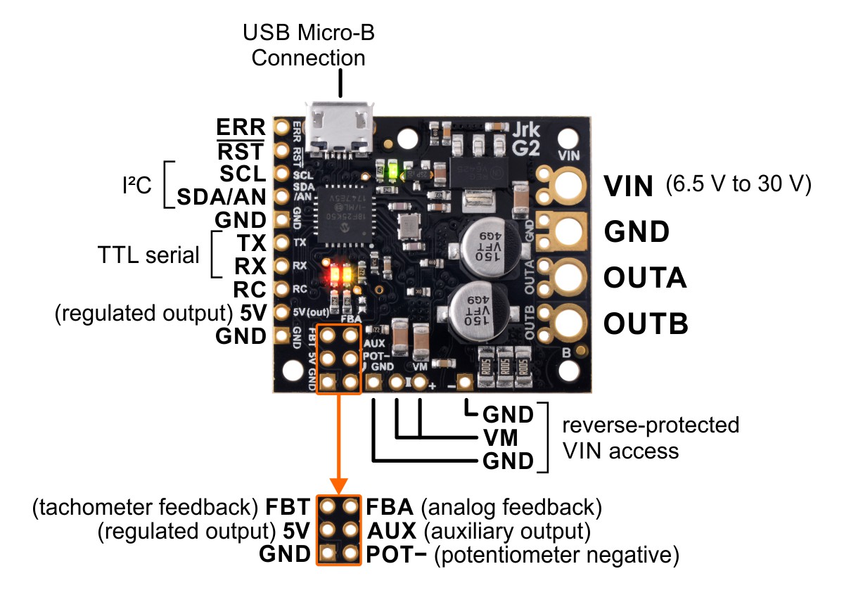 |
Basic pinout diagram of the Jrk G2 18v19 USB Motor Controller with Feedback. |
|---|
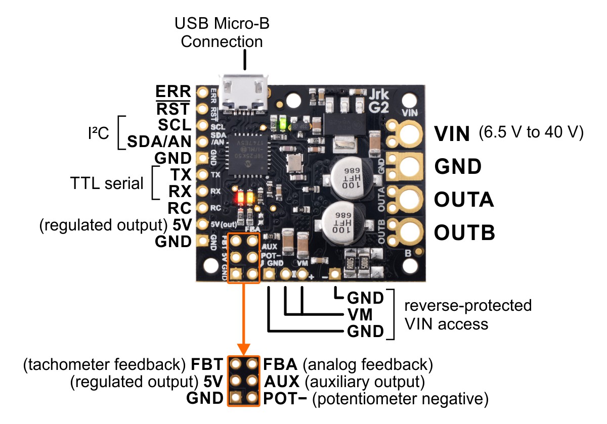 |
Basic pinout diagram of the Jrk G2 24v13 USB Motor Controller with Feedback. |
|---|
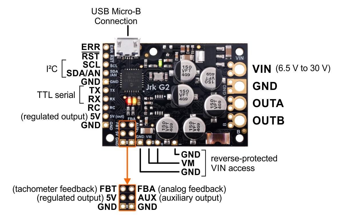 |
Basic pinout diagram of the Jrk G2 18v27 USB Motor Controller with Feedback. |
|---|
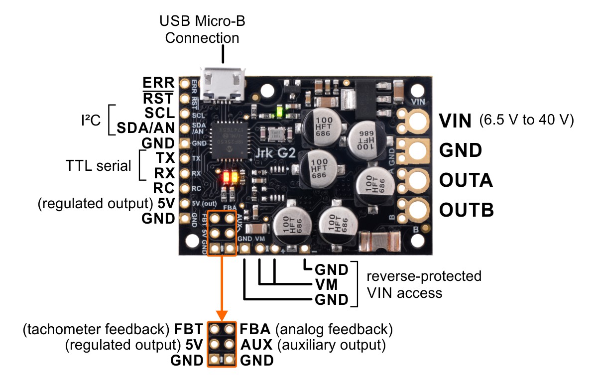 |
Basic pinout diagram of the Jrk G2 24v21 USB Motor Controller with Feedback. |
|---|
The Jrk G2 can connect to a computer’s USB port via a USB A to Micro-B cable (not included). The USB connection is used to configure the Jrk, and it can also be used to send commands, get status information, and send and receive TTL serial bytes.
Power connections
The through-holes on the right side of the board are for motor and power connections: your power supply should be connected to VIN and GND, and your motor leads should be connected to OUTA and OUTB. Section 4.2 goes into detail about connecting a motor and power supply to the Jrk.
A few smaller through-holes along the bottom edge of the board provide access to VM, the reverse-protected motor voltage. On the 24v21 and 18v27 versions, one of these VM access points and the GND access point to its right are partially blocked by a capacitor.
Control pins
The pins in a row along the left side of the PCB are mostly for providing control inputs to the Jrk.
The ERR pin is an optional output that is normally pulled low, but drives high to indicate when an error is stopping the motor. It is tied to the red error LED. For more information about error handling and the ERR pin, see Section 7.7.
The RST pin can be driven low to reset the Jrk’s microcontroller, but this should generally not be necessary for typical applications. The line is pulled up to 5 V so it is safe to leave this pin unconnected. You should wait at least 10 ms after a reset before sending commands to the Jrk.
The SCL and SDA/AN pins provide the Jrk’s I²C interface. For more information about setting up I²C control, see Section 6.3.
Additionally, SDA/AN and SCL serve different functions in analog input mode: SDA/AN is the analog input used to set the target of the system, and SCL can be used to supply 5 V to an input potentiometer and detect if it becomes disconnected. For more information about setting up analog control, see Section 6.4.
The TX and RX pins provide the Jrk’s TTL (0 V to 5 V) serial interface. Serial data can be commands and responses to and from the Jrk, arbitrary data exchanged between the TTL serial interface and the computer via USB, or both. For more information about setting up serial control and using the serial interface, see Section 6.2.
The RC pin is the Jrk’s control input for reading an RC hobby servo signal. For more information about setting up RC control, see Section 6.5.
The 5V pin provides access to the Jrk’s 5 V logic supply. See Section 7.8 for details.
The GND pins provide a ground reference for logic connections. (Note that your power supply ground should be connected to the large GND through-hole on the right side of the board, not the small 0.1″-spaced through-holes on the left.)
Feedback pins
The six grouped pins in the lower left corner of the Jrk PCB allow connection to a feedback sensor.
The FBT pin is the Jrk’s tachometer feedback input, used for a speed-measuring device that generates pulses at a rate proportional to the speed of the output. For information about setting up frequency feedback, see Section 5.3. The 5V and GND pins below FBT provide convenient power and ground connection points for the frequency sensor.
The FBA pin is the Jrk’s analog feedback input, used for a potentiometer or other analog voltage source that indicates the position of the output. For more information about setting up analog feedback, see Section 5.2.
The AUX pin can be used to supply 5 V power to a feedback potentiometer and detect if it becomes disconnected.
The POT− pin can be connected to a feedback potentiometer’s negative terminal and aids with disconnect detection. This pin is not present on the Jrk G2 18v27 and 24v21: those models have a GND pin in the same location that can be used for the same purpose (but does not provide additional disconnect detection like POT−). The POT− pin is connected to GND through an on-board 220Ω resistor.
Hardware design files
These files provide further documentation of the hardware design of the Jrk G2 21v3 motor controller:
- Dimension diagram (215k pdf)
- 3D model (11MB step)
- Drill guide (59k dxf)
These files provide further documentation of the hardware design of the Jrk G2 18v19 and 24v13 motor controllers:
- Dimension diagram (220k pdf)
- 3D model (11MB step)
- Drill guide (83k dxf)
These files provide further documentation of the hardware design of the Jrk G2 18v27 and 24v21 motor controllers:
- Dimension diagram (208k pdf)
- 3D model (11MB step)
- Drill guide (95k dxf)
9. Setting reference
The Jrk G2 holds all of its settings in its non-volatile EEPROM memory. These settings are normally set ahead of time over USB using the Jrk G2 Configuration Utility. You can also read and write settings from the Jrk over USB using the --get-settings and --settings arguments to jrk2cmd. You can use the Jrk’s “Get settings” command to read these settings over serial and I²C, but you cannot change the EEPROM settings using those interfaces.
The Jrk stores a temporary copy of its settings in RAM, and the “Set RAM settings” and “Get RAM settings” commands allow you read and write from this copy over serial, I²C, and USB. This allows you to temporarily override most (but not all) settings.
This section lists all of the settings that the Jrk G2 supports. For each setting, this section contains several pieces of information:
- The Offset of each setting is the location where it is stored in the Jrk’s EEPROM memory. The offset is measured in bytes. You can use this offset with the “Read setting” and “Set setting” commands.
- The Type of each setting specifies how many bits the setting occupies, and says whether it is signed or unsigned (if applicable). All the multi-byte settings use little-endian format, meaning that the least-significant byte comes first.
- The Data entry for each setting specifies how the data for that setting is encoded in the Jrk’s memory. Some of the settings lack this field because they are simply dimensionless integers, so their encoding is straightforward.
- The Default entry for each setting is the default value it has on a new Jrk or a Jrk that has been reset to its defaults.
- The Range entry for each setting specifies what values the setting can have, if applicable. Trying to use a value outside of this range could result in unexpected behavior.
- The Settings file is the name of the setting in a Jrk settings file, if applicable. You can save and load Jrk settings files from the “File” menu of the Configuration utility, or by using the Jrk Command-line Utility (jrk2cmd).
- The Settings file data entry for each setting is the specification of how that setting is encoded in a settings file. Some of the settings lack this field because the encoding is straightforward.
- The Configuration utility entry is the location of that setting in the graphical user interface of the Jrk G2 configuration utility software, if applicable.
- The Temporary override available entry is “Yes” if changes made to the setting with the “Set RAM settings” command will have an immediate effect. Otherwise, you will need to set this setting ahead of time over USB using Jrk G2 configuration software.
List of settings
- Input mode
- Input error minimum
- Input error maximum
- Input minimum
- Input maximum
- Input neutral minimum
- Input neutral maximum
- Target minimum
- Target neutral
- Target maximum
- Invert input direction
- Input scaling degree
- Input detect disconnect
- Input analog samples exponent
- Feedback mode
- Feedback error minimum
- Feedback error maximum
- Feedback minimum
- Feedback maximum
- Invert feedback direction
- Feedback detect disconnect
- Feedback dead zone
- Feedback analog samples exponent
- Feedback wraparound
- Serial mode
- Serial baud rate
- Serial timeout
- Serial device number
- Never sleep
- Enable CRC
- Enable 14-bit device number
- Disable compact protocol
- Proportional multiplier
- Proportional exponent
- Integral multiplier
- Integral exponent
- Derivative multiplier
- Derivative exponent
- PID period
- Integral divider exponent
- Integral limit
- Reset integral when proportional term exceeds max duty cycle
- PWM frequency
- Current samples exponent
- Hard overcurrent threshold
- Current offset calibration
- Current scale calibration
- Invert motor direction
- Max. duty cycle forward
- Max. duty cycle reverse
- Max. duty cycle while feedback is out of range
- Max. acceleration forward
- Max. acceleration reverse
- Max. deceleration forward
- Max. deceleration reverse
- Hard current limit forward
- Hard current limit reverse
- Brake duration forward
- Brake duration reverse
- Soft current limit forward
- Soft current limit reverse
- Soft current regulation level forward
- Soft current regulation level reverse
- Coast when off
- Error enable
- Error latch
- Error hard stop
- VIN calibration
- Disable I²C pull-ups
- Enable pull-up for analog input on SDA/AN
- Always configure SDA/AN for analog input
- Always configure FBA for analog input
- FBT method
- FBT timing clock
- FBT timing polarity
- FBT timing timeout
- FBT samples
- FBT divider exponent
- Not initialized
Input mode
| Offset | 0x03 |
|---|---|
| Type | unsigned 8-bit |
| Data |
|
| Default | Serial / I²C / USB |
| Settings file | input_mode |
| Settings file data |
|
| Configuration utility | Input tab, Input mode |
| Temporary override available | No |
The input mode setting specifies how you want to control the Jrk. It determines the definition of the input and target variables. The input variable is a raw measurement of the Jrk’s input. The target variable is the desired state of the system’s output, and feeds into the PID feedback algorithm.
- If the input mode is “Serial / I²C / USB”, the Jrk gets its input and target settings over its USB, serial, or I²C interfaces. You can send Set Target commands to the Jrk to set both the input and target variables.
- If the input mode is “Analog voltage”, the Jrk gets it input variable by reading the voltage on its SDA/AN pin. A signal level of 0 V corresponds to an input value of 0, and a signal level of 5 V corresponds to an input value of 4092. The Jrk uses its input scaling feature to set the target variable.
- If the input mode is “RC”, the Jrk gets it input variable by reading RC pulses on its RC pin. The input value is the width of the most recent pulse, in units of 2/3 microseconds (0.666 μs). The Jrk uses its input scaling feature to set the target variable.
Input error minimum
| Offset | 0x04 |
|---|---|
| Type | unsigned 16-bit |
| Default | 0 |
| Range | 0 to 4095 |
| Settings file | input_error_minimum |
| Configuration utility | Input tab, Scaling box, Input column, Error min |
| Temporary override available | Yes |
If the raw input value is below this value, it causes an “Input disconnect” error. See Section 7.3.
Input error maximum
| Offset | 0x06 |
|---|---|
| Type | unsigned 16-bit |
| Default | 4095 |
| Range | 0 to 4095 |
| Settings file | input_error_maximum |
| Configuration utility | Input tab, Scaling box, Input column, Error max |
| Temporary override available | Yes |
If the raw input value is below this value, it causes an “Input disconnect” error. See Section 7.3.
Input minimum
| Offset | 0x08 |
|---|---|
| Type | unsigned 16-bit |
| Default | 0 |
| Range | 0 to 4095 |
| Settings file | input_minimum |
| Configuration utility | Input tab, Scaling box, Input column, Minimum |
| Temporary override available | Yes |
This is one of the input scaling parameters that determines how the Jrk calculates its target value from its raw input. See Section 7.3.
Input maximum
| Offset | 0x0A |
|---|---|
| Type | unsigned 16-bit |
| Default | 4095 |
| Range | 0 to 4095 |
| Settings file | input_maximum |
| Configuration utility | Input tab, Scaling box, Input column, Maximum |
| Temporary override available | Yes |
This is one of the input scaling parameters that determines how the Jrk calculates its target value from its raw input. See Section 7.3.
Input neutral minimum
| Offset | 0x0C |
|---|---|
| Type | unsigned 16-bit |
| Default | 2048 |
| Range | 0 to 4095 |
| Settings file | input_neutral_minimum |
| Configuration utility | Input tab, Scaling box, Input column, Neutral min |
| Temporary override available | Yes |
This is one of the input scaling parameters that determines how the Jrk calculates its target value from its raw input. See Section 7.3.
Input neutral maximum
| Offset | 0x0E |
|---|---|
| Type | unsigned 16-bit |
| Default | 2048 |
| Range | 0 to 4095 |
| Settings file | input_neutral_maximum |
| Configuration utility | Input tab, Scaling box, Input column, Neutral max |
| Temporary override available | Yes |
This is one of the input scaling parameters that determines how the Jrk calculates its target value from its raw input. See Section 7.3.
Target minimum
| Offset | 0x10 |
|---|---|
| Type | unsigned 16-bit |
| Default | 0 |
| Range | 0 to 4095 |
| Settings file | output_minimum |
| Configuration utility | Input tab, Scaling box, Target column, Minimum |
| Temporary override available | Yes |
This is one of the input scaling parameters that determines how the Jrk calculates its target value from its raw input. See Section 7.3.
Target neutral
| Offset | 0x12 |
|---|---|
| Type | unsigned 16-bit |
| Default | 2048 |
| Range | 0 to 4095 |
| Settings file | output_neutral |
| Configuration utility | Input tab, Scaling box, Target column, Neutral |
| Temporary override available | Yes |
This is one of the input scaling parameters that determines how the Jrk calculates its target value from its raw input. See Section 7.3.
Target maximum
| Offset | 0x14 |
|---|---|
| Type | unsigned 16-bit |
| Default | 4095 |
| Range | 0 to 4095 |
| Settings file | output_maximum |
| Configuration utility | Input tab, Scaling box, Target column, Maximum |
| Temporary override available | Yes |
This is one of the input scaling parameters that determines how the Jrk calculates its target value from its raw input. See Section 7.3.
Invert input direction
| Offset | bit 0 of byte 0x02 |
|---|---|
| Type | boolean |
| Data |
|
| Default | false |
| Settings file | input_invert |
| Settings file data | true or false |
| Configuration utility | Input tab, Scaling box, Invert input direction |
| Temporary override available | Yes |
This is one of the input scaling parameters that determines how the Jrk calculates its target value from its raw input. See Section 7.3.
Input scaling degree
| Offset | 0x16 |
|---|---|
| Type | unsigned 8-bit |
| Data |
|
| Default | JRK_SCALING_DEGREE_LINEAR |
| Settings file | input_scaling_degree |
| Settings file data |
|
| Configuration utility | Input tab, Scaling box, Degree |
| Temporary override available | Yes |
This is one of the input scaling parameters that determines how the Jrk calculates its target value from its raw input. See Section 7.3.
Input detect disconnect
| Offset | bit 1 of byte 0x02 |
|---|---|
| Type | boolean |
| Data |
|
| Default | false |
| Settings file | input_detect_disconnect |
| Settings file data | true or false |
| Configuration utility | Input tab, Detect disconnect with power pin (SCL) |
| Temporary override available | Yes |
This determines whether the Jrk will drive the SCL pin low to detect when the input potentiometer has been disconnected. See Section 7.3.
Input analog samples exponent
| Offset | 0x17 |
|---|---|
| Type | unsigned 8-bit |
| Default | 7 (128 samples) |
| Range | 0 to 10 (1 sample to 1024 samples) |
| Settings file | input_analog_samples_exponent |
| Configuration utility | Input tab, Analog samples |
| Temporary override available | Yes |
This setting specifies how many analog samples of the SDA/AN pin to take each PID period if it is being used as an analog input. The number of samples will be 2x where x is this setting. For more information, see Section 7.3.
Feedback mode
| Offset | 0x18 |
|---|---|
| Type | unsigned 8-bit |
| Data |
|
| Default | None |
| Settings file | feedback_mode |
| Settings file data |
|
| Configuration utility | Feedback tab, Feedback mode |
| Temporary override available | No |
The feedback mode setting specifies whether the Jrk is using feedback from the output of the system, and if so defines what type of feedback to use.
- If the feedback mode is “None”, feedback and PID calculations are disabled, and the Jrk will do open-loop control. The duty cycle target variable is always equal to the target variable minus 2048, instead of being the result of a PID calculation. This means that a target of 2648 corresponds to driving the motor at full speed forward, 2048 is stopped, and 1448 is full-speed reverse. See Section 5.1.
- If the feedback mode is “Analog voltage”, the Jrk gets its feedback by measuring the voltage on the FBA pin. A level of 0 V corresponds to a feedback value of 0, and a level of 5 V corresponds to a feedback value of 4092. The feedback scaling algorithm computes the scaled feedback variable, and the PID algorithm uses the scaled feedback and the target to compute the duty cycle target. See Section 7.4.
- If the feedback mode is “Frequency (speed control)”, the Jrk gets it feedback by measuring the frequency of a digital signal on the FBT pin. This mode is only suitable for speed control, not position control. See Section 7.4.
Feedback error minimum
| Offset | 0x19 |
|---|---|
| Type | unsigned 16-bit |
| Default | 0 |
| Range | 0 to 4095 |
| Settings file | feedback_error_minimum |
| Configuration utility | Feedback tab, Error min |
| Temporary override available | Yes |
If the raw feedback value is below this value, it causes a “Feedback disconnect” error. See Section 7.4.
Feedback error maximum
| Offset | 0x1B |
|---|---|
| Type | unsigned 16-bit |
| Default | 4095 |
| Range | 0 to 4095 |
| Settings file | feedback_error_maximum |
| Configuration utility | Feedback tab, Error max |
| Temporary override available | Yes |
If the raw feedback value exceeds this value, it causes a “Feedback disconnect” error. See Section 7.4.
Feedback minimum
| Offset | 0x1D |
|---|---|
| Type | unsigned 16-bit |
| Default | 0 |
| Range | 0 to 4095 |
| Settings file | feedback_minimum |
| Configuration utility | Feedback tab, Minimum |
| Temporary override available | Yes |
This is one of the parameters of the feedback scaling feature. See Section 7.4.
Feedback maximum
| Offset | 0x1F |
|---|---|
| Type | unsigned 16-bit |
| Default | 4095 |
| Range | 0 to 4095 |
| Settings file | feedback_maximum |
| Configuration utility | Feedback tab, Maximum |
| Temporary override available | Yes |
This is one of the parameters of the feedback scaling feature. See Section 7.4.
Invert feedback direction
| Offset | bit 2 of byte 0x02 |
|---|---|
| Type | boolean |
| Data |
|
| Default | false |
| Settings file | feedback_invert |
| Settings file data | true or false |
| Configuration utility | Feedback tab, Invert feedback direction |
| Temporary override available | Yes |
This is one of the parameters of the feedback scaling feature. See Section 7.4.
Feedback detect disconnect
| Offset | bit 3 of byte 0x02 |
|---|---|
| Type | boolean |
| Data |
|
| Default | false |
| Settings file | feedback_detect_disconnect |
| Settings file data | true or false |
| Configuration utility | Feedback tab, Detect disconnect with power pin (AUX) |
| Temporary override available | Yes |
This determines whether the Jrk will drive AUX low to detect if the feedback potentiometer has been disconnected. See Section 7.4.
Feedback dead zone
| Offset | 0x21 |
|---|---|
| Type | unsigned 8-bit |
| Default | 0 |
| Range | 0 to 255 |
| Settings file | feedback_dead_zone |
| Configuration utility | PID tab, Feedback dead zone |
| Temporary override available | Yes |
If PID feedback is enabled, the Jrk sets the duty cycle target to zero and resets the integral whenever the magnitude of the error is smaller than this setting. See Section 7.5.
Feedback analog samples exponent
| Offset | 0x22 |
|---|---|
| Type | unsigned 8-bit |
| Default | 7 (128 samples) |
| Range | 0 to 10 (1 sample to 1024 samples) |
| Settings file | feedback_analog_samples_exponent |
| Configuration utility | Feedback tab, Analog samples |
| Temporary override available | Yes |
This setting specifies how many analog samples of the FBA pin to take each PID period if it is being used as an analog input. The number of samples will be 2x where x is this setting. The samples are averaged together. For more information, see Section 7.4.
Feedback wraparound
| Offset | bit 4 of byte 0x02 |
|---|---|
| Type | boolean |
| Data |
|
| Default | false |
| Settings file | feedback_wraparound |
| Settings file data | true or false |
| Configuration utility | Feedback tab, Wraparound |
| Temporary override available | Yes |
This option, which is only available when the feedback mode is “Analog”, determines whether the PID algorithm will consider a scaled feedback value of 0 to be next to a scaled feedback value of 4095 when calculating the error. See Section 7.4.
Serial mode
| Offset | 0x23 |
|---|---|
| Type | unsigned 8-bit |
| Data |
|
| Default | USB dual port |
| Settings file | serial_mode |
| Settings file data |
|
| Configuration utility | Input tab, Serial interface box (radio buttons) |
| Temporary override available | No |
The serial mode determines how bytes are transferred between the Jrk’s UART (TX and RX pins), its two USB virtual serial ports (the command port and the TTL Port), and its serial command processor.
- If the serial mode is “USB dual port”, the command port can be used to send commands to the Jrk and receive responses from it, while the TTL port can be used to send and receives bytes on the TX and RX lines. The baud rate set by the USB host on the TTL port determines the baud rate used on the TX and RX lines.
- If the serial mode is “USB chained”, the command port can be used to both transmit bytes on the TX line and send commands to the Jrk. The Jrk’s responses to those commands will be sent to the command port but not the TX line. If the RX line is enabled as a serial receive line, bytes received on the RX line will be sent to the command port but will not be interpreted as command bytes by the Jrk. The baud rate set by the USB host on the command port determines the baud rate used on the TX and RX lines.
- If the serial mode is “UART”, the TX and RX lines can be used to send commands to the Jrk and receive responses from it. Any byte received on RX will be sent to the command port, but bytes sent from the command port will be ignored.
Serial baud rate
| Offset | 0x24 |
|---|---|
| Type | unsigned 16-bit |
| Data | 16-bit baud rate generator (see below) |
| Default | 0x4E1 (9600 bits per second) |
| Settings file | serial_baud_rate |
| Settings file data | Baud rate in bits per second |
| Configuration utility | Input tab, Serial interface box, fixed baud rate |
| Temporary override available | No |
This setting specifies the baud rate to use on the RX and TX pins when the serial mode is UART. In other serial modes, the baud rate defaults to 9600, but can be changed over USB using the standard USB CDC ACM command.
The settings file and the configuration utility show the baud rate in bits per second, but it is actually stored on the Jrk as an unsigned 16-bit integer called the baud rate generator. The baud rate will be 12 Mbps divided by the baud rate generator.
Serial timeout
| Offset | 0x26 |
|---|---|
| Type | unsigned 16-bit |
| Data | Timeout in units of 10 ms |
| Default | 0 |
| Range | 0 to 655,350 ms |
| Settings file | serial_timeout |
| Settings file data | Timeout in units of milliseconds |
| Configuration utility | Input tab, Serial interface, Timeout (s) |
| Temporary override available | Yes |
This is the time before the device reports a “Serial timeout error” if it has not received certain commands. A value of 0 disables the command timeout feature. See Section 7.7 for details about the serial timeout error.
The configuration utility presents the timeout in seconds, with two digits after the decimal point. The settings file has the timeout in units of milliseconds. The Jrk itself stores it as an unsigned 16-bit number with units of 10 ms, so the maximum possible value is 655,350 ms.
Serial device number
| Offset | 0x28 |
|---|---|
| Type | unsigned 16-bit |
| Default | 11 |
| Range | 0 to 16383 |
| Settings file | serial_device_number |
| Configuration utility | Input tab, Serial interface, Device number |
| Temporary override available | No |
This is the serial device number used in the Pololu protocol on the Jrk’s serial interfaces, and the I²C device address used on the Jrk’s I²C interface.
By default, the Jrk only pays attention to the lower 7 bits of this setting, but if you enable 14-bit serial device numbers then it will use the lower 14 bits for the serial interface (but the I²C interface will still only use the lower 7 bits).
See Section 12 and Section 13.
Never sleep
| Offset | bit 0 of byte 0x01 |
|---|---|
| Type | boolean |
| Data |
|
| Default | false |
| Settings file | never_sleep |
| Settings file data | true or false |
| Configuration utility | Advanced tab, Miscellaneous, Never sleep (ignore USB suspend) |
| Temporary override available | Yes |
By default, if the Jrk is powered from a USB bus that is in suspend mode (e.g. the computer is sleeping) and VIN power is not present, it will go to sleep to reduce its current consumption and comply with the USB specification. If this setting is set to true, the Jrk will never go to sleep.
Enable CRC
| Offset | bit 1 of byte 0x01 |
|---|---|
| Type | boolean |
| Data |
|
| Default | false |
| Settings file | serial_enable_crc |
| Settings file data | true or false |
| Configuration utility | Input tab, Serial interface, Enable CRC |
| Temporary override available | No |
If set to true, the Jrk requires a 7-bit CRC byte at the end of each serial command, and if the CRC byte is wrong then it ignores the command and sets the serial CRC error bit. See Section 12.
Enable 14-bit device number
| Offset | bit 2 of byte 0x01 |
|---|---|
| Type | boolean |
| Data |
|
| Default | false |
| Settings file | serial_enable_14bit_device_number |
| Settings file data | true or false |
| Configuration utility | Input tab, Serial interface, Enable 14-bit device number |
| Temporary override available | No |
If enabled, the Jrk’s Pololu protocol for serial commands will require a 14-bit device number to be sent with every command, instead of normal 7-bit device number. This option allows you to put more than 128 Jrk devices on one serial bus and control them individually. See Section 12.
Disable compact protocol
| Offset | bit 3 of byte 0x01 |
|---|---|
| Type | boolean |
| Data |
|
| Default | false |
| Settings file | serial_disable_compact_protocol |
| Settings file data | true or false |
| Configuration utility | Input tab, Serial interface, Disable compact protocol |
| Temporary override available | No |
If enabled, the Jrk will not respond to compact protocol serial commands. See Section 12.
Proportional multiplier
| Offset | 0x51 |
|---|---|
| Type | unsigned 16-bit |
| Default | 0 |
| Range | 0 to 1023 |
| Settings file | proportional_multiplier |
| Configuration utility | PID tab, Proportional coefficient, Upper left |
| Temporary override available | Yes |
This is the multiplier for the proportional coefficient used in the PID calculation. See Section 7.5.
Proportional exponent
| Offset | 0x53 |
|---|---|
| Type | unsigned 8-bit |
| Default | 0 |
| Range | 0 to 18 |
| Settings file | proportional_exponent |
| Configuration utility | PID tab, Proportional coefficient, Lower left |
| Temporary override available | Yes |
This is the exponent for the proportional coefficient used in the PID calculation. See Section 7.5.
Integral multiplier
| Offset | 0x54 |
|---|---|
| Type | unsigned 16-bit |
| Default | 0 |
| Range | 0 to 1023 |
| Settings file | integral_multiplier |
| Configuration utility | PID tab, Integral coefficient, Upper left |
| Temporary override available | Yes |
This is the multiplier for the integral coefficient used in the PID calculation. See Section 7.5.
Integral exponent
| Offset | 0x56 |
|---|---|
| Type | unsigned 8-bit |
| Default | 0 |
| Range | 0 to 18 |
| Settings file | integral_exponent |
| Configuration utility | PID tab, Integral coefficient, Lower left |
| Temporary override available | Yes |
This is the exponent for the integral coefficient used in the PID calculation. See Section 7.5.
Derivative multiplier
| Offset | 0x57 |
|---|---|
| Type | unsigned 16-bit |
| Default | 0 |
| Range | 0 to 1023 |
| Settings file | derivative_multiplier |
| Configuration utility | PID tab, Derivative coefficient, Upper left |
| Temporary override available | Yes |
This is the multiplier for the derivative coefficient used in the PID calculation. See Section 7.5.
Derivative exponent
| Offset | 0x59 |
|---|---|
| Type | unsigned 8-bit |
| Default | 0 |
| Range | 0 to 18 |
| Settings file | derivative_exponent |
| Configuration utility | PID tab, Derivative coefficient, Lower left |
| Temporary override available | Yes |
This is the exponent for the derivative coefficient used in the PID calculation. See Section 7.5.
PID period
| Offset | 0x5A |
|---|---|
| Type | unsigned 16-bit |
| Data | PID period in units of milliseconds |
| Default | 10 ms |
| Range | 1 ms to 8191 ms |
| Settings file | pid_period |
| Configuration utility | PID tab, PID period |
| Temporary override available | Yes |
The PID period specifies how often the Jrk should calculate its input and feedback, run its PID calculation, and update the motor speed, in units of milliseconds. This period is still used even if feedback and PID are disabled. See Section 7.5.
Integral divider exponent
| Offset | 0x3F |
|---|---|
| Type | unsigned 8-bit |
| Default | 0 |
| Range | 0 to 15 |
| Settings file | integral_divider_exponent |
| Configuration utility | PID tab, Integral divider |
| Temporary override available | Yes |
This setting determines the “Integral divider” described in Section 7.5. The integral divider is 2x where x is this setting.
Integral limit
| Offset | 0x5C |
|---|---|
| Type | unsigned 16-bit |
| Default | 1000 |
| Range | 0 to 32767 |
| Settings file | integral_limit |
| Configuration utility | PID tab, Integral limit |
| Temporary override available | Yes |
See Section 7.5.
Reset integral when proportional term exceeds max duty cycle
| Offset | bit 0 of byte 0x50 |
|---|---|
| Type | boolean |
| Data |
|
| Default | false |
| Settings file | reset_integral |
| Settings file data | true or false |
| Configuration utility | PID tab, Reset integral when proportional term exceeds max duty cycle |
| Temporary override available | Yes |
See Section 7.5.
PWM frequency
| Offset | 0x32 |
|---|---|
| Type | unsigned 8-bit |
| Data |
|
| Default | 20 kHz |
| Settings file | pwm_frequency |
| Settings file data | 20 or 5 |
| Configuration utility | Motor tab, PWM frequency |
| Temporary override available | Yes |
See Section 7.6.
Current samples exponent
| Offset | 0x33 |
|---|---|
| Type | unsigned 8-bit |
| Default | 7 (128 samples) |
| Range | 0 to 10 (1 sample to 1024 samples) |
| Settings file | current_samples_exponent |
| Configuration utility | Motor tab, Current samples |
| Temporary override available | Yes |
This setting specifies how many analog samples of the Jrk’s internal current sense pin to take each PID period. The number of samples will be 2x where x is this setting. The samples are averaged together. For more information, see Section 7.6.
Hard overcurrent threshold
| Offset | 0x34 |
|---|---|
| Type | unsigned 8-bit |
| Default | 1 |
| Range | 1 to 255 |
| Settings file | hard_overcurrent_threshold |
| Configuration utility | Motor tab, Hard overcurrent threshold |
| Temporary override available | Yes |
This setting is only available for the Jrk G2 18v19, 24v13, 18v27, and 24v21. See Section 7.6.
Current offset calibration
| Offset | 0x35 |
|---|---|
| Type | signed 16-bit |
| Default | 0 |
| Range | -800 to 800 |
| Settings file | current_offset_calibration |
| Configuration utility | Motor tab, Current offset calibration |
| Temporary override available | Yes |
See Section 7.6.
Current scale calibration
| Offset | 0x37 |
|---|---|
| Type | signed 16-bit |
| Default | 0 |
| Range | -1875 to 1875 |
| Settings file | current_scale_calibration |
| Configuration utility | Motor tab, Current scale calibration |
| Temporary override available | Yes |
See Section 7.6.
Invert motor direction
| Offset | bit 5 of byte 0x02 |
|---|---|
| Type | boolean |
| Data |
|
| Default | false |
| Settings file | motor_invert |
| Settings file data | true or false |
| Configuration utility | Motor tab, Invert motor direction |
| Temporary override available | Yes |
Flips the polarity of the voltage applied to the motor. See Section 7.6.
Max. duty cycle forward
| Offset | 0x68 |
|---|---|
| Type | unsigned 16-bit |
| Default | 600 |
| Range | 0 to 600 |
| Settings file | max_duty_cycle_forward |
| Configuration utility | Motor tab, Max. duty cycle, Forward column |
| Temporary override available | Yes |
See Section 7.6.
Max. duty cycle reverse
| Offset | 0x6A |
|---|---|
| Type | unsigned 16-bit |
| Default | 600 |
| Range | 0 to 600 |
| Settings file | max_duty_cycle_reverse |
| Configuration utility | Motor tab, Max. duty cycle, Reverse column |
| Temporary override available | Yes |
See Section 7.6.
Max duty cycle while feedback is out of range
| Offset | 0x5E |
|---|---|
| Type | unsigned 16-bit |
| Default | 600 |
| Range | 1 to 600 |
| Settings file | max_duty_cycle_while_feedback_out_of_range |
| Configuration utility | Motor tab, Max. duty cycle while feedback is out of range |
| Temporary override available | Yes |
See Section 7.6.
Max. acceleration forward
| Offset | 0x60 |
|---|---|
| Type | unsigned 16-bit |
| Default | 600 |
| Range | 1 to 600 |
| Settings file | max_acceleration_forward |
| Configuration utility | Motor tab, Max. acceleration, Forward column |
| Temporary override available | Yes |
See Section 7.6.
Max. acceleration reverse
| Offset | 0x62 |
|---|---|
| Type | unsigned 16-bit |
| Default | 600 |
| Range | 1 to 600 |
| Settings file | max_acceleration_reverse |
| Configuration utility | Motor tab, Max. acceleration, Reverse column |
| Temporary override available | Yes |
See Section 7.6.
Max. deceleration forward
| Offset | 0x64 |
|---|---|
| Type | unsigned 16-bit |
| Default | 600 |
| Range | 1 to 600 |
| Settings file | max_deceleration_forward |
| Configuration utility | Motor tab, Max. deceleration, Forward column |
| Temporary override available | Yes |
See Section 7.6.
Max. deceleration reverse
| Offset | 0x66 |
|---|---|
| Type | unsigned 16-bit |
| Default | 600 |
| Range | 1 to 600 |
| Settings file | max_deceleration_reverse |
| Configuration utility | Motor tab, Max. deceleration, Reverse column |
| Temporary override available | Yes |
See Section 7.6.
Hard current limit forward
| Offset | 0x6C |
|---|---|
| Type | unsigned 16-bit |
| Data | Encoded |
| Default | Depends on the product |
| Settings file | encoded_hard_current_limit_forward |
| Configuration utility | Motor tab, Hard current limit, Forward column |
| Temporary override available | Yes |
This setting specifies the hardware current limit that the Jrk will use when driving in the forward direction.
This setting is not actually stored in the Jrk as a current; it is stored as an encoded value telling the Jrk how to set up its current limiting hardware. The correspondence between the encoded value and the actual current limit in milliamps depends on what product you are using and the characteristics of your particular unit as represented by the “Current offset calibration” and “Current scale calibration” settings. You can get a table in CSV format showing the correspondence by connecting the Jrk into a computer via USB and running jrk2cmd --current-table.
The default value for this setting depends on what Jrk product you have, as described in the table below:
| Jrk product | Default hard current limit |
|---|---|
| 18v19 | 28.47 A (86) |
| 24v13 | 19.34 A (62) |
| 18v27 | 40.25 A (87) |
| 24v21 | 31.53 A (63) |
This setting is only available for the Jrk G2 18v19, 24v13, 18v27, and 24v21. See Section 7.6 for more information.
Hard current limit reverse
| Offset | 0x6E |
|---|---|
| Type | unsigned 16-bit |
| Data | Encoded |
| Default | Depends on the product |
| Settings file | encoded_hard_current_limit_reverse |
| Configuration utility | Motor tab, Hard current limit, Reverse column |
| Temporary override available | Yes |
See the hard current limit forward setting. This setting is the same except it applies when driving in the reverse direction. This setting is only available for the Jrk G2 18v19, 24v13, 18v27, and 24v21.
Brake duration forward
| Offset | 0x70 |
|---|---|
| Type | unsigned 8-bit |
| Data | Duration in units of 5 ms |
| Default | 0 |
| Range | 0 to 1275 ms |
| Settings file | brake_duration_forward |
| Settings file data | Duration in units of milliseconds |
| Configuration utility | Motor tab, Brake duration, Forward column |
| Temporary override available | Yes |
See Section 7.6.
Brake duration reverse
| Offset | 0x71 |
|---|---|
| Type | unsigned 8-bit |
| Data | Duration in units of 5 ms |
| Default | 0 |
| Range | 0 to 1275 ms |
| Settings file | brake_duration_reverse |
| Settings file data | Duration in units of milliseconds |
| Configuration utility | Motor tab, Brake duration, Reverse column |
| Temporary override available | Yes |
See Section 7.6.
Soft current limit forward
| Offset | 0x72 |
|---|---|
| Type | unsigned 16-bit |
| Data | Current in units of milliamps, 0 means no limit |
| Default | 0 |
| Range | 0 to 65,535 mA |
| Settings file | soft_current_limit_forward |
| Settings file data | Current in units of milliamps |
| Configuration utility | Motor tab, Soft current limit, Forward column |
| Temporary override available | Yes |
See Section 7.6.
Soft current limit reverse
| Offset | 0x74 |
|---|---|
| Type | unsigned 16-bit |
| Data | Current in units of milliamps, 0 means no limit |
| Default | 0 |
| Range | 0 to 65,535 mA |
| Settings file | soft_current_limit_reverse |
| Settings file data | Current in units of milliamps |
| Configuration utility | Motor tab, Soft current limit, Reverse column |
| Temporary override available | Yes |
See Section 7.6.
Soft current regulation level forward
| Offset | 0x40 |
|---|---|
| Type | unsigned 16-bit |
| Data | Current in units of milliamps, 0 means disabled |
| Default | 0 |
| Range | 0 to 65,535 mA |
| Settings file | soft_current_regulation_level_forward |
| Settings file data | Current in units of milliamps |
| Configuration utility | Motor tab, Soft current regulation level, Forward column |
| Temporary override available | Yes |
This setting is only available on the Jrk G2 21v3. See Section 7.6.
Soft current regulation level reverse
| Offset | 0x42 |
|---|---|
| Type | unsigned 16-bit |
| Data | Current in units of milliamps, 0 means disabled |
| Default | 0 |
| Range | 0 to 65,535 mA |
| Settings file | soft_current_regulation_level_reverse |
| Settings file data | Current in units of milliamps |
| Configuration utility | Motor tab, Soft current regulation level, Reverse column |
| Temporary override available | Yes |
This setting is only available on the Jrk G2 21v3. See Section 7.6.
Coast when off
| Offset | bit 1 of byte 0x50 |
|---|---|
| Type | boolean |
| Data |
|
| Default | false |
| Settings file | coast_when_off |
| Settings file data | true or false |
| Configuration utility | Motor tab, When motor is off |
| Temporary override available | Yes |
See Section 7.6.
Error enable
| Offset | 0x2A |
|---|---|
| Type | unsigned 16-bit |
| Default | 0 |
| Settings file | error_enable |
| Configuration utility | Errors tab |
| Temporary override available | Yes |
This setting holds a bit for each error that the Jrk supports. The correspondence between bits and errors is defined in Section 7.7. The bit is 1 if the corresponding error is enabled, and 0 otherwise. Note that an error that is “Enabled & latched” counts as being enabled.
The “Awaiting command”, “No power”, “Motor driver error”, and “Input invalid” errors are always enabled and cannot be disabled, so the bits corresponding to those errors in this setting are ignored.
Error latch
| Offset | 0x2C |
|---|---|
| Type | unsigned 16-bit |
| Default | 0 |
| Settings file | error_latch |
| Configuration utility | Errors tab |
| Temporary override available | Yes |
This setting holds a bit for each error that the Jrk supports. The correspondence between bits and errors is defined in Section 7.7. The bit is 1 if the corresponding error is enabled and latched, or 0 otherwise.
The bits in this register are ignored for errors that are not enabled. (If an error is not enabled, its error flag will never be set, so there is no concept of the error flag being latched.) Also, the “Awaiting command” error and all the serial errors are always latching errors if they are enabled, so bits corresponding to those errors in this setting are ignored.
Error hard stop
| Offset | 0x2E |
|---|---|
| Type | unsigned 16-bit |
| Default | 0 |
| Settings file | error_hard |
| Configuration utility | Errors tab |
| Temporary override available | Yes |
This setting holds a bit for each error that the Jrk supports. The correspondence between bits and errors is defined in Section 7.7. The bit is 1 if the corresponding error is configured as a hard stop error, or 0 otherwise.
The “No power” and “Motor driver” errors are always hard stop errors. The bits corresponding to those errors in this setting are ignored.
VIN calibration
| Offset | 0x30 |
|---|---|
| Type | signed 16-bit |
| Default | 0 |
| Range | -500 to 500 |
| Settings file | vin_calibration |
| Configuration utility | Advanced tab, Miscellaneous, VIN measurement calibration |
| Temporary override available | Yes |
The firmware uses this calibration factor when calculating the VIN voltage. One of the steps in the process is to multiply the VIN voltage reading by 825 plus the VIN calibration. Therefore, for every 8 counts that you add or subtract from the VIN calibration setting, you increase or decrease the VIN voltage reading by about 1%.
Disable I²C pull-ups
| Offset | bit 4 of byte 0x01 |
|---|---|
| Type | boolean |
| Data |
|
| Default | false |
| Settings file | disable_i2c_pullups |
| Settings file data | true or false |
| Configuration utility | Advanced tab, Disable I²C pull-ups |
| Temporary override available | No |
This option disables the internal pull-up resistors on the SDA/AN and SCL pins if those pins are being used for I²C communication. Normally, the pull-ups are enabled to ensure that each bus line goes high when no devices are driving it.
Enable pull-up for analog input on SDA/AN
| Offset | bit 5 of byte 0x01 |
|---|---|
| Type | boolean |
| Data |
|
| Default | false |
| Settings file | analog_sda_pullup |
| Settings file data | true or false |
| Configuration utility | Advanced tab, Enable pull-up for analog input on SDA/AN |
| Temporary override available | No |
This option enables the internal pull-up resistor on the SDA/AN pin if it is being used as an analog input.
Always configure SDA/AN for analog input
| Offset | bit 6 of byte 0x01 |
|---|---|
| Type | boolean |
| Data |
|
| Default | false |
| Settings file | always_analog_sda |
| Settings file data | true or false |
| Configuration utility | Advanced tab, Always configure SDA/AN for analog input |
| Temporary override available | No |
This option causes the Jrk to perform analog measurements on the SDA/AN pin and configure SCL as a potentiometer power pin even if the “Input mode” setting is not “Analog”.
Always configure FBA for analog input
| Offset | bit 7 of byte 0x01 |
|---|---|
| Type | boolean |
| Data |
|
| Default | false |
| Settings file | always_analog_fba |
| Settings file data | true or false |
| Configuration utility | Advanced tab, Always configure FBA for analog input |
| Temporary override available | No |
This option causes the Jrk to perform analog measurements on the FBA pin even if the “Feedback mode” setting is not “Analog”.
FBT method
| Offset | 0x39 |
|---|---|
| Type | unsigned 8-bit |
| Data |
|
| Default | Pulse counting |
| Settings file | fbt_method |
| Settings file data |
|
| Configuration utility | Feedback tab, Frequency feedback on FBT, Measurement method |
| Temporary override available | No |
See Section 7.4.
FBT timing clock
| Offset | bits 4 through 6 of byte 0x3A |
|---|---|
| Type | unsigned 8-bit |
| Data |
|
| Default | 1.5 MHz |
| Range | 0 to JRK_FBT_TIMING_CLOCK_24 |
| Settings file | fbt_timing_clock |
| Settings file data |
|
| Configuration utility | Feedback tab, Frequency feedback on FBT, Pulse timing clock |
| Temporary override available | No |
See Section 7.4.
FBT timing polarity
| Offset | bit 0 of byte 0x3A |
|---|---|
| Type | boolean |
| Data |
|
| Default | Active high |
| Settings file | fbt_timing_polarity |
| Settings file data | false (active high) or true (active low) |
| Configuration utility | Feedback tab, Frequency feedback on FBT, Pulse timing polarity |
| Temporary override available | No |
By default, the pulse timing mode on the FBT pin measures the time of high pulses. When true, this option causes it to measure low pulses. See Section 7.4.
FBT timing timeout
| Offset | 0x3B |
|---|---|
| Type | unsigned 16-bit |
| Data | Timeout in milliseconds |
| Default | 100 |
| Range | 1 to 60000 |
| Settings file | fbt_timing_timeout |
| Configuration utility | Feedback tab, Frequency feedback on FBT, Pulse timing timeout |
| Temporary override available | Yes |
The pulse timing mode for the FBT pin will assume the motor has stopped, and start recording maximum-width pulses if it has not seen any pulses in this amount of time. See Section 7.4.
FBT samples
| Offset | 0x3D |
|---|---|
| Type | unsigned 8-bit |
| Default | 1 |
| Range | 1 to 32 |
| Settings file | fbt_samples |
| Configuration utility | Feedback tab, Frequency feedback on FBT, Pulse samples |
| Temporary override available | No |
The number of consecutive FBT measurements to average together in pulse timing mode or to add together in pulse counting mode. See Section 7.4.
FBT divider exponent
| Offset | 0x3E |
|---|---|
| Type | unsigned 8-bit |
| Default | 0 |
| Range | 0 to 15 |
| Settings file | fbt_divider_exponent |
| Configuration utility | Feedback tab, Frequency feedback on FBT, Frequency divider |
| Temporary override available | Yes |
This setting determines the “Frequency divider” described in Section 7.4. The frequency divider is 2x where x is this setting.
Not initialized
| Offset | 0x00 |
|---|---|
| Type | unsigned 8-bit |
| Data |
|
| Default | false |
This special setting keeps track of whether the rest of the settings have been initialized or not. Normally it is zero, which means false. If you set it to a non-zero value, then the Jrk will reset all of the settings to their default values the next time the Jrk is reset or reinitialized. This is how the “Restore default settings” command in the Jrk G2 Configuration Utility and the --restore-defaults option in the command-line utility are implemented.
10. Variable reference
The Jrk G2 maintains a set of variables in RAM that contain information about its inputs, outputs, and status. Many of these variables are displayed in real time in the “Status” tab of the Jrk G2 Configuration Utility. You can also retrieve variables from the Jrk over USB by running jrk2cmd --status or jrk2cmd --status --full (the --full option shows every variable). The Jrk’s “Get variable” and “Get variables” commands allow you to read the variables over serial, USB, and I²C.
This section lists all of the variables that the Jrk G2 supports. For each variable, this section contains several pieces of information, if applicable:
- The Offset of each variable is its location within the variable data. The offset is measured in bytes. You can use this offset to specify which variables you want to read in the “Get variable” and “Get variables” commands.
- The Type of each variable specifies how many bits the variable occupies, and says whether it is signed or unsigned. All the multi-byte variables use little-endian format, meaning that the least-significant byte comes first.
- The Range of each variable specifies what values the variable can have.
- The Units of each variable specify the relationship between values of the variable real-world quantities.
- The Data of each variable indicates how to interpret different possible values of the variable.
List of variables
- Input
- Target
- Feedback
- Scaled feedback
- Integral
- Duty cycle target
- Duty cycle
- Current (low resolution)
- PID period exceeded
- PID period count
- Error flags halting
- Error flags occurred
- Force mode
- VIN voltage
- Current
- Last reset
- Up time
- RC pulse width
- FBT reading
- Analog reading SDA/AN
- Analog reading FBA
- Digital readings
- Raw current
- Hard current limit
- Last duty cycle
- Current chopping consecutive count
- Current chopping occurrence count
Input
| Offset | 0x00 |
|---|---|
| Type | unsigned 16-bit |
| Range | 0 to 4095 |
| Units | Depends on the input mode |
The input variable is a raw, unscaled value representing a measurement taken by the Jrk of the input to the system. The meaning of this variable depends on the “Input mode” setting. In serial input mode, the input is equal to the target, which can be set to any value from 0 to 4095 over serial, USB, and I²C. In analog input mode, the input is a measurement the voltage on the SDA pin, where 0 is 0 V and 4092 is a voltage equal the Jrk’s 5V pin (approximately 4.8 V). In RC input mode, the input is the duration of the last pulse measured, in units of 2/3 us.
Target
| Offset | 0x02 |
|---|---|
| Type | unsigned 16-bit |
| Range | 0 to 4095 |
The target variable represents the speed or position that you are commanding the Jrk to maintain.
In serial input mode, the target is set directly with serial, USB, or I²C commands.
In the other input modes, the target is computed by scaling the Input variable using the configurable input scaling settings (see Section 7.3).
If feedback is enabled, the Jrk tries to drive the motor to make the Scaled feedback variable equal to the target (see Section 7.5).
If the feedback mode is “None” (open-loop speed control mode), the target directly determines the Duty cycle target variable that tells the Jrk how much voltage to apply to the motor (see Section 5.1).
Feedback
| Offset | 0x04 |
|---|---|
| Type | unsigned 16-bit |
| Range | 0 to 4095 |
| Units | Depends on the feedback mode |
The feedback variable is a raw, unscaled feedback value representing a measurement taken by the Jrk of the output of the system. In analog mode, the feedback is a measurement of the voltage on the FBA pin, where 0 is 0 V and 4092 is a voltage equal to the Jrk’s 5V pin (approximately 4.8 V). In frequency feedback mode, the feedback is 2048 plus or minus a measurement of the frequency of pulses on the FBT pin. See Section 7.4 for more information about analog and frequency feedback. If the feedback mode is “None” (open-loop speed control mode), the feedback is always zero.
Scaled feedback
| Offset | 0x06 |
|---|---|
| Type | unsigned 16-bit |
| Range | 0 to 4095 |
If feedback is enabled, the scaled feedback is calculated from the Feedback using the Jrk’s configurable feedback scaling settings (see Section 7.4). Generally, when feedback is enabled, the Jrk tries to drive the motor to make the scaled feedback equal to the Target (see Section 7.5).
Integral
| Offset | 0x08 |
|---|---|
| Type | signed 16-bit |
| Range | Plus or minus the “Integral limit” setting |
In general, every PID period, the error (Scaled feedback minus Target) is added to the integral (also known as error sum). There are several settings to configure the behavior of this variable, and it is used in the PID calculation. See Section 7.5.
Duty cycle target
| Offset | 0x0A |
|---|---|
| Type | signed 16-bit |
| Range | −32,768 to 32,767 |
| Units | −600 is full speed reverse, 600 is full speed forward |
In general, this is the duty cycle that the jrk is trying to achieve. A value of −600 or less means full speed reverse, while a value of 600 or more means full speed forward. A value of 0 means stopped (braking or coasting).
When the feedback mode is “None” (open-loop speed control mode), the duty cycle target is normally the target minus 2048. In other feedback modes, the duty cycle target is normally zero minus the sum of the proportional, integral, and derivative terms of the PID algorithm (see Section 7.5). In any mode, the duty cycle target can be overridden with a “Force duty cycle target” command.
If an error is stopping the motor, the duty cycle target variable will not be directly affected, but the duty cycle variable will change/decelerate to zero.
Duty cycle
| Offset | 0x0C |
|---|---|
| Type | signed 16-bit |
| Range | −600 to 600 |
| Units | −600 is full speed reverse, 600 is full speed forward |
The duty cycle variable indicates the voltage that the Jrk is currently applying to the motor. A value of −600 means full speed reverse, while a value of 600 means full speed forward. A value of 0 means stopped (braking or coasting). The duty cycle could be different from the Duty cycle target because it normally takes into account the Jrk’s configurable motor limits and errors, and its absolute value cannot exceed 600. The duty cycle can be overridden with a “Force duty cycle” command.
Current (low resolution)
| Offset | 0x0E |
|---|---|
| Type | unsigned 8-bit |
| Units | 256 mA |
This variable is the upper 8 bits of the higher-resolution current variable described below, and it only exists for compatibility with the original Jrk 12v12 and Jrk 21v3. For new applications, we recommend using the Current variable instead.
PID period exceeded
| Offset | bit 0 of byte 0x0F |
|---|---|
| Type | boolean |
| Range | 0 or 1 |
This variable is true if the Jrk’s most recent PID cycle took more time than the configured PID period. This indicates that the Jrk does not have time to perform all of its tasks at the desired rate. Most often, this is caused by the configured number of analog samples for input, feedback, or current sensing being too high for the configured PID period.
PID period count
| Offset | 0x10 |
|---|---|
| Type | unsigned 16-bit |
This is the number of PID periods that have elapsed. It resets to 0 after reaching 65535.
Error flags halting
| Offset | 0x12 |
|---|---|
| Type | unsigned 16-bit |
This variable indicates which errors are currently stopping the motor. Each bit in the variable represents a different error. Each bit in this register will only be set to 1 if the corresponding error is enabled. See Section 7.7.
Error flags occurred
| Offset | 0x14 |
|---|---|
| Type | unsigned 16-bit |
This variable indicates which errors have occurred since the last time the variable was cleared, regardless of whether the error is enabled or not. Each bit in the variable represents a different error. See Section 7.7.
Force mode
| Offset | bits 0 and 1 of byte 0x16 |
|---|---|
| Data |
|
This variable indicates whether the Jrk is currently obeying a “Force duty cycle” or “Force duty cycle target” command. A value of 0 indicates normal operation, a value of 1 means the duty cycle target is being forced, and a value of 2 means the duty cycle is being forced.
VIN voltage
| Offset | 0x17 |
|---|---|
| Type | unsigned 16-bit |
| Units | mV |
This is the measurement of the voltage supplied to the Jrk’s VIN pin, in millivolts.
Current
| Offset | 0x19 |
|---|---|
| Type | unsigned 16-bit |
| Units | mA |
This is the Jrk’s measurement of the current running through the motor, in milliamps. See Section 7.6 for more details about current measurement.
Last reset
| Offset | 0x1F |
|---|---|
| Type | unsigned 8-bit |
| Data |
|
This is the cause of the Jrk’s last full microcontroller reset.
Up time
| Offset | 0x20 |
|---|---|
| Type | unsigned 32-bit |
| Range | 0 to 4,294,967,295 |
| Units | ms |
This is the time since the last full reset of the Jrk’s microcontroller, in milliseconds. It resets to 0 after reaching 4,294,967,295.
RC pulse width
| Offset | 0x24 |
|---|---|
| Type | unsigned 16-bit |
| Range | 2400 (200 µs) to 32400 (2700 µs) or 0 |
| Units | 1/12 µs |
This is the raw RC pulse width measured on the Jrk’s RC input, in units of twelfths of a microsecond. A value of 0 means the RC input is missing or invalid. The jrk always measures this input, even if the RC signal is not being used to control the motor.
FBT reading
| Offset | 0x26 |
|---|---|
| Type | unsigned 16-bit |
| Units | Depends on the FBT settings |
This is the raw pulse rate or pulse width measured on the Jrk’s FBT (tachometer feedback) pin. The Jrk always measures this input, even if the FBT reading is not being used for feedback.
In pulse counting mode, this will be the number of pulses on the FBT pin seen in the last N PID periods, where N is the “Pulse samples” setting.
In pulse timing mode, this will be a measurement of the width of pulses on the FBT pin. This measurement is affected by several configurable settings.
Analog reading SDA/AN
| Offset | 0x28 |
|---|---|
| Type | unsigned 16-bit |
| Range | 0 to 65,472 or 65,535 |
| Units | 0 means 0 V, 65,472 means roughly the voltage on the Jrk’s 5V pin |
This is the analog reading on the SDA/AN pin. The Jrk updates this reading once per PID period if the “Input mode” setting is “Analog voltage” or the “Always configure SDA/AN for analog input” setting is enabled. Otherwise, the value of this variable will be 65,535 (0xFFFF), indicating that the input is not enabled.
Analog reading FBA
| Offset | 0x2A |
|---|---|
| Type | unsigned 16-bit |
| Range | 0 to 65,472 or 65,535 |
| Units | 0 means 0 V, 65,472 means roughly the voltage on the Jrk’s 5V pin |
This is the analog reading on the FBA pin. The Jrk updates this reading once per PID period if the “Feedback mode” setting is “Analog voltage” or the “Always configure FBA for analog input” setting is enabled. Otherwise, the value of this variable will be 65,535 (0xFFFF), indicating that the input is not enabled.
Digital readings
| Offset | 0x2C |
|---|---|
| Type | unsigned 8-bit |
| Data |
|
This variable contains digital readings for the Jrk’s control pins. Each pin corresponds to a bit in this variable. The Jrk disables digital readings for pins that are used as analog inputs (except SDA when its internal pull-up is enabled), so the digital readings of those pins will always be zero.
Raw current
| Offset | 0x2D |
|---|---|
| Type | unsigned 16-bit |
| Units | Depends on the hard current limit |
This is an analog voltage reading from the Jrk’s internal current sense pin. The units of the reading depend on the Encoded hard current limit. The Jrk Configuration Utility and jrk2cmd convert this reading to millivolts before displaying it.
Hard current limit
| Offset | 0x2F |
|---|---|
| Type | unsigned 16-bit |
This variable specifies the hardware current limit that the Jrk is currently using.
This variable is not actually a current; it is an encoded value telling the Jrk how to set up its current limiting hardware. It is encoded in the same way as the “Hard current limit forward” and “Hard current limit reverse” settings. This variable is only available on the Jrk G2 18v19, 24v13, 18v27, and 24v21.
Last duty cycle
| Offset | 0x31 |
|---|---|
| Type | signed 16-bit |
| Range | −600 to 600 |
| Units | −600 is full speed reverse, 600 is full speed forward |
This is the duty cycle from the previous PID period. The Jrk reports this variable because it is used in the calculation of the measured current, and you might want to reproduce that calculation yourself instead of relying on the Jrk’s Current variable. The other Duty cycle variable indicates the final outcome of the Jrk’s feedback and PID algorithms, and it is the duty cycle that the Jrk is going to use for the next period. This variable indicates the duty cycle that the Jrk was using during the previous period, so it is the duty cycle that was being used while the Raw current reading was measured.
Current chopping consecutive count
| Offset | 0x33 |
|---|---|
| Type | unsigned 8-bit |
| Range | 0 to 255 |
This is the number of consecutive PID periods during which current chopping due to the hard current limit has been active. When it reaches 255, it stops increasing. This variable is only available on the Jrk G2 18v19, 24v13, 18v27, and 24v21. The Jrk 21v3 cannot sense when current chopping occurs.
Current chopping occurrence count
| Offset | 0x34 |
|---|---|
| Type | unsigned 8-bit |
| Range | 0 to 255 |
This is the number of PID periods during which current chopping due to the hard current limit has been active, since the last time the variable was cleared. The PID periods counted here are not necessarily consecutive. This variable is only available on the Jrk G2 18v19, 24v13, 18v27, and 24v21. The Jrk 21v3 cannot sense when current chopping occurs.
11. Command reference
The Jrk G2 supports several different commands on its serial, I²C, and USB interfaces. This section describes the details of what each command does. The encoding of the commands for the different interfaces is described in later sections (Section 12 for serial, Section 13 for I²C, and Section 14 for USB).
For each command, this section contains several pieces of information:
- The list of Interfaces that support the command. Most of the commands are available on all three interfaces, but some of them are only available over USB.
- The Arguments that the command takes. This is the data you must supply to the Jrk G2 when sending the command.
- The Response is the data that the Jrk will return to you after you send the command.
- The jrk2cmd field shows how to run the command using the Jrk G2 Command-line Utility. Be sure to replace
NUMwith an actual number andFILEwith a filename if you try to run these commands. - The Arduino library field describes how to send the command using our Jrk G2 Library for Arduino.
List of commands
- Set target
- Stop motor
- Force duty cycle target
- Force duty cycle
- Get variables
- Set RAM settings
- Get RAM settings
- Get EEPROM settings
- Set EEPROM setting (USB only)
- Reinitialize (USB only)
- Start bootloader (USB only)
Set target
| Interfaces | Serial, I²C, USB |
|---|---|
| Arguments | Target: a number between 0 and 4095 |
| Response | None |
| jrk2cmd | jrk2cmd --target NUMjrk2cmd --run |
| Arduino library | jrk.setTarget(uint16_t target) |
The “Set target” command is the most important command for controlling the Jrk, and in many applications it is the only command needed. The target can represent a target duty cycle, speed, or position depending on the feedback mode.
If the input mode is serial, this command sets the “Input” and “Target” variables equal to specified target value, which should be between 0 and 4095. In any input mode, it clears the “Awaiting command” error flag, clears the serial timeout timer, and terminates the effect of any previous “Force duty cycle” and “Force duty cycle target” commands.
You can send this command using the Jrk G2 Configuration Utility. If the input mode is serial, you can specify the target value to send using scroll bar in the “Status” tab. In any input mode, you can click “Run motor” to clear latched errors and send a “Set target” command.
You can also send this command using the Jrk G2 Command-line Utility, jrk2cmd. The --target NUM option allows you to specify a target. For example, you can run jrk2cmd --target 1234 to send a Set Target command with an argument of 1234. You can run jrk2cmd --run to clear latched errors and send a “Set target” command that sets the target to its current value in order to trigger the side effects of the command that are described above. You can add the -d NUM option to either of the commands above to specify the serial number of the Jrk you want to control, which is required if there are multiple Jrk controllers connected to the computer over USB.
Stop motor
| Interfaces | Serial, I²C, USB |
|---|---|
| Arguments | None |
| Response | None |
| jrk2cmd | jrk2cmd --stop NUM |
| Arduino library | jrk.stopMotor() |
The “Stop motor” command, also known as “Motor off”, sets the “Awaiting command” error flag and clears the serial timeout timer. You can use this command to stop the motor in any input mode.
If you have configured a deceleration limit, the Jrk will respect the deceleration limit while decelerating to a duty cycle of 0, unless the “Awaiting command” error has been configured as a hard stop error. Once the duty cycle reaches zero, the Jrk will either brake or coast, depending on its settings.
You can send this command using the Jrk G2 Configuration Utility by pressing the “Stop motor” button. You can send this command using the Jrk G2 Command-line Utility by running jrk2cmd --stop from a command prompt.
Force duty cycle target
| Interfaces | Serial, I²C, USB |
|---|---|
| Arguments | Duty cycle target: a number between −600 and 600 |
| Response | None |
| jrk2cmd | jrk2cmd --force-duty-cycle-target NUM |
| Arduino library | jrk.forceDutyCycleTarget() |
When the Jrk receives this command, it will start ignoring the results of the usual algorithm for choosing the duty cycle target, and instead set it to be equal to the target specified by this command. This command clears the “Awaiting command” error flag and clears the serial timeout timer. While this command is in effect, the Jrk will set its “Integral” variable to 0.
This command is useful if the Jrk is configured to use feedback and PID but you want to take control of the motor for some time, while still respecting errors and motor limits as usual. It could also be useful to temporarily take control of a Jrk that is normally controlled via an analog or RC input.
To get out of this mode, send a Set target, Force duty cycle, Stop motor, or Reinitialize command.
Force duty cycle
| Interfaces | Serial, I²C, USB |
|---|---|
| Arguments | Duty cycle: a number between −600 and 600 |
| Response | None |
| jrk2cmd | jrk2cmd --force-duty-cycle NUM |
| Arduino library | jrk.forceDutyCycle() |
When the Jrk receives this command, it will start ignoring the results of the usual algorithm for choosing the duty cycle, and instead set it to be equal to the value specified by this command, ignoring all motor limits except the maximum duty cycle parameters, and ignoring the “Input invalid”, “Input disconnect”, and “Feedback disconnect” errors. This command will have an immediate effect, regardless of the PID period. This command clears the “Awaiting command” error flag and clears the serial timeout timer. The Jrk will set its “Integral” variable to 0 while in this mode.
This is useful if the Jrk is configured to use feedback and PID but you want to take control of the motor for some time, without respecting most motor limits. It could also be useful to temporarily take control of a Jrk that is normally controlled via an analog or RC input.
To get out of this mode, send a Set target, Force duty cycle target, Stop motor, or Reinitialize command.
Get variables
| Interfaces | Serial, I²C, USB |
|---|---|
| Arguments | Offset: The address of the first variable to fetch. Length: The number of bytes to fetch. Clear error flags halting: true or false Clear error flags occurred: true or false Clear current chopping occurrence count: true or false |
| Response | The requested bytes. |
| jrk2cmd | jrk2cmd --statusjrk2cmd --status --full(or use -s instead of --status) |
| Arduino library | jrk.getVariables(uint8_t offset, uint8_t length, uint8_t * buffer)jrk.get___() functions |
This command fetches a range of bytes from the Jrk’s variables, which are stored in the Jrk’s RAM and represent the current state of the Jrk. The offset argument specifies the location of the first byte you want to fetch: an offset of zero indicates the first variable (the “Input” variable). The length argument specifies how many bytes to read. Each variable, along with its offset and size, is documented in Section 10.
For example, if you want to read the 16-bit VIN voltage variable, you can specify an offset of 23 (0x17 when written in hexadecimal) and a length of 2. The Jrk will return the two bytes of that variable. If you want to read the feedback and scaled feedback variables together, you can specify an offset of 4 and a length of 4, since the offset of the feedback variable is 4 and the scaled feedback variable it stored immediately after it at offset 6.
It is OK to read past the last variable. The Jrk will return zeroes when you try to read from any unimplemented areas of the variable space.
When reading multiple variables, the Jrk will give you a consistent snapshot of the state of those variables as they were at the end of the previous PID period. The snapshot is taken right after the Jrk has finished calculating a new duty cycle and stored it in the “Duty cycle” variable. When the Jrk receives a “Get variables” command, it copies the requested data into a dedicated buffer, so the variables in the response to that command will be consistent with each other.
This command has several optional side effects:
- If the clear error flags halting argument is true, the Jrk will clear latched errors in its “Error flags halting” variable, except for the “Awaiting command” error flag. It will also clear the serial timeout timer.
- If the clear error flags occurred argument is true, the Jrk will clear errors in its “Error flags occurred” variable.
- If the clear current chopping occurrence count argument is true, the Jrk will clear its “Current chopping occurrence count” variable (i.e. reset it to zero).
These side effects take place after the variable data has been copied into a dedicated buffer to be sent as a response to the command. This means that you can reliably detect errors and current chopping even if you are constantly clearing the corresponding variables, as long as you read from those variables at the same time as clearing them.
The Jrk G2 Configuration Utility reads the Jrk’s variables over USB many times per second, and displays many of them in the “Status” tab. It sets the “Clear error flags occurred” and “Clear current chopping occurrence count” flags to true so it can get rough counts of how many times an error has occurred, or how many times current chopping has occurred. This means that you might have trouble detecting that those errors happened if you are trying to read them while the configuration utility is running.
The “Clear errors” button in the “Errors” tab of the Jrk G2 Configuration Utility sends this command with the “Clear error flags halting” parameter set to true.
The Jrk’s USB interface provides a flexible version of the “Get variables” command that lets you specify an offset, length, and any combination of side effects. The serial and I²C commands are less flexible: the length is limited to be at most 15 bytes, and the side effects can only be triggered using special variants of the “Get variables” command that retrieve the variable being cleared. For more details, see the command encoding specifications in the following sections.
Set RAM settings
| Interfaces | Serial, I²C, USB |
|---|---|
| Arguments | Offset: The address of the first setting to write to. Length: The number of bytes to write. Data: The bytes to write. |
| Response | None |
| jrk2cmd | jrk2cmd --ram-settings FILERun jrk2cmd --help and look at the other “RAM (volatile) settings” options. |
| Arduino library | jrk.setRAMSettings(uint8_t offset, uint8_t length, uint8_t * buffer)jrk.set___() functions documented in the “RAM settings commands” section of the library documentation |
This command temporarily overrides the selected settings by writing to the copy of the settings that the Jrk stores in RAM. Each setting is documented in Section 9, along with its offset and size and whether it can be temporarily overridden.
For example, if you want to temporarily override the proportional PID coefficient, you could send a “Set RAM settings” command with an offset of 0x51 and a length of 2. The offset of the “Proportional multiplier” setting is 0x51 and it occupies 2 bytes. You could change the length to 3 if you want to also override the “Proportional exponent” setting, which is one byte long and lives at offset 0x53.
The Jrk firmware does not validate or fix any of the settings that you provide with this command. If you choose invalid settings then you might get some unexpected behavior. The usual way to change the Jrk’s settings is to use the Jrk G2 Configuration Utility or Jrk G2 Command-line Utility, which validate the settings and fix any errors before writing them to the Jrk’s EEPROM memory.
It is OK to write past the end of the last setting. The Jrk will ignore these writes, and always report zero when you try to read from unimplemented areas of the settings space with the Get RAM settings command.
The effect of this command is temporary. The Jrk reloads all of its settings from EEPROM whenever there is a full microcontroller reset and whenever it receives a Reinitialize command.
The Jrk G2 Command-line Utility has a --ram-settings option that you can use to override all of the Jrk’s RAM settings. It requires a settings file, which you can obtain with jrk2cmd --get-settings FILE, jrk2cmd --get-ram-settings FILE, or from the “File” menu of the Jrk G2 Configuration Utility. It also supports a variety of more streamlined options that just override a small number of settings instead of overriding all of them.
The Jrk G2 Configuration Utility does not support this command.
Get RAM settings
| Interfaces | Serial, I²C, USB |
|---|---|
| Arguments | Offset: The address of the first setting to read. Length: The number of bytes to read. |
| Response | The requested bytes. |
| jrk2cmd | jrk2cmd --get-ram-settings FILE |
| Arduino library | jrk.getRAMSettings(uint8_t offset, uint8_t length, uint8_t * buffer)jrk.get___() functions documented in the “RAM settings commands” section of the library documentation |
This command reads from the copy of the settings that the Jrk stores in RAM. You can use this to retrieve the current values of these settings, in case any of them have been temporarily overridden with the Set RAM settings command.
It is OK to read past the end of the last setting. The Jrk will always return zeros when you try to read from unimplemented areas of the settings space.
Get EEPROM settings
| Interfaces | Serial, I²C, USB |
|---|---|
| Arguments | Offset: The address of the first setting to read. Length: The number of bytes to read. |
| Response | The requested bytes. |
| jrk2cmd | jrk2cmd --get-settings FILE |
| Arduino library | jrk.getEEPROMSettings(uint8_t offset, uint8_t length, uint8_t * buffer) |
This command reads the specified bytes from the Jrk’s EEPROM memory, where the non-volatile copy of its settings are stored. Each setting is documented in Section 9, along with its offset and size.
Set EEPROM setting (USB only)
| Interfaces | USB only |
|---|---|
| Arguments | Offset: The address of the byte to write to. Value: The new value of the byte, from 0 to 255. |
| Response | None |
| jrk2cmd | jrk2cmd --settings FILE |
This command modifies the specified byte in the Jrk’s EEPROM. Each setting is documented in Section 9, along with its offset and size.
The Jrk G2 Configuration Utility uses this command many times whenever you click “Apply settings”. The Jrk G2 Command-line Utility uses this command to apply a settings file specified with the --settings option. In both cases, the software also sends a Reinitialize command to make the new settings take effect.
The Jrk’s EEPROM is only rated 100,000 erase/write cycles, so be careful about using this command in a loop.
Reinitialize (USB only)
| Interfaces | USB only |
|---|---|
| Arguments | Preserve errors: true or false |
| Response | None |
| jrk2cmd | jrk2cmd --reinitialize |
This command tells the Jrk to reload all of its settings from non-volatile memory (discarding changes made by previous Set RAM settings commands), make the settings take effect, and terminate the effect of any previous “Force duty cycle” and “Force duty cycle target” commands.
If the Preserve errors argument is true, this command will clear all of the error bits in “Error flags halting” for errors that are not enabled in the new settings. If the input mode is changing from some other input mode to “Serial / I²C / USB”, the Jrk will set the “Awaiting command” error, so that the Jrk does not drive the motor before it gets a valid command. The Jrk G2 software sets the “Preserve errors” flag to true whenever it applies settings.
If the Preserve errors argument is false, this command will behave as it did on the original Jrk controllers. It will clear all of the bits in “Error flags halting”, but if the input mode is serial then it will immediately set the “Awaiting command” error bit, meaning that you will have to send a command to get the Jrk moving again.
Start bootloader (USB only)
| Interfaces | USB only |
|---|---|
| Arguments | None |
| Response | None |
This command causes the Jrk to go into bootloader in preparation for receiving a firmware upgrade over USB. It will briefly disconnect from USB and reappear as a new USB device.
12. Serial command encoding
This section documents how the Jrk G2’s commands are encoded as a sequence of bytes within serial packets, which can either be sent to the Jrk’s TTL serial interface (the RX and TX lines) or the Jrk’s USB Command Port.
The Jrk’s serial mode setting, which can be set from the “Input” tab, determines which interfaces of the Jrk accept serial commands. In “USB Dual Port” and “USB chained” mode, the Jrk only accepts serial commands from its Command Port. In “UART” mode, the Jrk only accepts serial commands from the TX and RX lines. For more information about the serial mode setting, see Section 9.
The Jrk supports two different serial protocols. The compact protocol does not include any kind of device number or address, so it is intended for cases where the commands you are sending will only be seen by one device, and that device is the Jrk. The Pololu protocol includes a device number, allowing you to control multiple devices from a single serial line. This section starts by documenting the compact protocol version of each command. Later on, this section describes how to convert those commands to the Pololu protocol, and other settings that affect the serial protocol.
Both protocols use a byte with its most significant bit set (i.e. between 128 and 255) to indicate the start of a new command. This byte is called the command byte, and every command begins with a command byte.
In the tables below that document the format of each command, each cell of a table represents a single byte. Number prefixed with “0x” are written in hexadecimal notation (base 16) and numbers prefixed with “0b” are written in binary notation (base 2). Numbers with these prefixes are written with their most significant digits first, just like regular decimal numbers.
For a reference implementation of the Jrk G2 serial protocols, see the Jrk G2 library for Arduino. For example code that shows how to use some of the Jrk’s serial commands from a computer, see Section 15.
For information about what these commands do and how to pick their parameters, see Section 11.
Set target (high resolution)
| 0xC0 + target low 5 bits | target high 7 bits |
For example, if you want to send a “Set Target” command to set the target to 3229 (0b110010011101 in binary), you could send the following two bytes:
| in binary: | 0b11011101 | 0b01100100 |
| in hex: | 0xDD | 0x64 |
| in decimal: | 221 | 100 |
Here is some example C code that will generate the correct serial bytes, given an integer target that holds the desired target (0–4095) and an array called serialBytes:
serialBytes[0] = 0xC0 + (target & 0x1F); // Command byte holds the lower 5 bits of target.
serialBytes[1] = (target >> 5) & 0x7F;   // Data byte holds the upper 7 bits of target.
Many motor control applications do not need 12 bits of target resolution. If you want a simpler and lower-resolution set of commands for setting the target, you can use the low-resolution command encodings documented below. Alternatively, you could use the high resolution version above with the lower 5 bits of the target always zero. Sending a 0xC0 byte followed by a data byte (0–127) will result in setting the target to a value of 32 multiplied by the data byte.
Set target (low resolution forward)
| 0xE1 | magnitude |
This is an alternative way to encode the “Set Target” command that provides less resolution and only works for target values of 2048 or greater. The target value is calculated from the magnitude byte (0–127) according to a formula that depends on what feedback mode the Jrk has been configured to use.
If the Jrk’s feedback mode is “Analog voltage” or “Frequency”, the formula for the target is:
 |
If the feedback mode is “None” (open-loop speed control), then the formula is:
 |
This means that a magnitude of 127 corresponds to full-speed forward, while a magnitude of 0 will make the motor stop.
Set target (low resolution reverse)
| 0xE0 | magnitude |
This is an alternative way to encode the “Set Target” command that provides less resolution and only works for target values of 2048 or less. It generally behaves the same as the “Set target (low resolution forward)” command encoding described above, except that the plus sign in each formula is replaced with a minus sign. The one exception is that if the magnitude byte is zero, then this command acts as a “Stop motor” command instead of a “Set target” command.
Stop motor
| 0xFF |
Force duty cycle target
| 0xF2 | duty cycle low 7 bits | duty cycle high 7 bits |
This command takes a duty cycle between −600 and 600. The duty cycle is expressed as a signed 14-bit two’s complement number, with the lower 7 bits in the first data byte and the upper 7 bits in the second data byte. Bit 13 of the duty cycle (which gets stored in bit 6 of the last data byte) acts as a sign bit.
Another way to think about the encoding of this command is that you should add 16,384 to any negative number to make it be positive before converting it to an unsigned 14-bit binary number.
For example, to send −300, we first encode it as a signed 14-bit two’s complement number, which is 0b11111011010100. We can verify that this is correct by calculating the binary representation of 16384−300, which yields the same sequence of bits. We put the least significant 7 bits in the first data byte and the most significant 7 bits in the second data byte to form this three-byte command:
| in binary: | 0b11110010 | 0b01010100 | 0b01111101 |
| in hex: | 0xF2 | 0x54 | 0x7D |
| in decimal: | 242 | 84 | 125 |
The following example C code shows how to generate the correct serial bytes, given an integer duty_cycle that holds the desired duty cycle (−600 to 600) and an array called serialBytes. The first step is to convert duty_cycle to a uint16_t (a standard type provided by including stdint.h) so there is no question about what the bit shifting operators will do when applied to a sign number.
uint16_t d = duty_cycle;  // convert to unsigned
serialBytes[0] = 0xF2;  // Force duty cycle target
serialBytes[1] = d & 0x7F;
serialBytes[2] = d >> 7 & 0x7F;
Force duty cycle
| 0xF4 | duty cycle low 7 bits | duty cycle high 7 bits |
This command is encoded in the same way as the “Force duty cycle target” command described above, except that the command byte is 0xF4 instead of 0xF2.
Get variables
| 0xE5 | offset | length |
This command lets you read any of the Jrk’s variables, without clearing them or having other side effects. The offset byte specifies the offset into the variable data (in bytes), while the length byte specifies how many bytes to read (in bytes). The length must be between 1 and 15. After the Jrk receives this command, it will send the requested bytes as a response. Multi-byte variables use little-endian format, so the least-significant byte comes first.
Get variables (one-byte commands)
There are also several one-byte versions of the “Get variables” command which are limited to reading one or two bytes and only support some of the Jrk’s variables. Some of these commands will clear the corresponding variable as a side effect. The command bytes are listed below:
| Command byte | Response (and effect) |
|---|---|
| 0xA1 | Both bytes of the “Input” variable. |
| 0x81 | The low byte (least-significant byte) of the “Input” variable. |
| 0x82 | The high byte (most-significant byte) of the "Input variable. |
| 0xA3 | Both bytes of “Target”. |
| 0x83 | The low byte of “Target”. |
| 0x84 | The high byte of “Target”. |
| 0xA5 | Both bytes of “Feedback”. |
| 0x85 | The low byte of “Feedback”. |
| 0x86 | The high byte of “Feedback”. |
| 0xA7 | Both bytes of “Scaled feedback”. |
| 0x87 | The low byte of “Scaled feedback”. |
| 0x88 | The high byte of “Scaled feedback”. |
| 0xA9 | Both bytes of “Integral”. |
| 0x89 | The low byte of “Integral”. |
| 0x8A | The high byte of “Integral”. |
| 0xAB | Both bytes of “Duty cycle target”. |
| 0x8B | The low byte of “Duty cycle target”. |
| 0x8C | The high byte of “Duty cycle target”. |
| 0xAD | Both bytes of “Duty cycle”. |
| 0x8D | The low byte of “Duty cycle”. |
| 0x8E | The high byte of “Duty cycle”. |
| 0x8F | The “Current (low resolution)” variable (one byte). |
| 0x90 | The “PID period exceeded” variable (one byte). |
| 0xB1 | Both bytes of “PID period count”. |
| 0x91 | The low byte of “PID period count”. |
| 0x92 | The high byte of “PID period count”. |
| 0xB3 | Both bytes of “Error flags halting”. Clears the variable as a side effect. |
| 0x93 | The low byte of “Error flags halting”. |
| 0x94 | The low byte of “Error flags halting”. |
| 0xB5 | Both bytes of “Error flags occurred”. Clears it as a side effect. |
| 0x95 | The low byte of “Error flags occurred”. |
| 0x96 | The high byte of “Error flags occurred”. |
| 0x97 | The “Force mode” variable (one byte). |
| 0xB8 | Both bytes of the “VIN voltage” variable. |
| 0x98 | The low byte of the “VIN voltage” variable. |
| 0x99 | The high byte of the “VIN voltage” variable. |
| 0xB9 | Both bytes of the “Current” variable. |
| 0x99 | The low byte of the “Current” variable. |
| 0x9A | The high byte of the "Current variable. |
| 0xEC | The “Current chopping occurrence count” variable (one byte). Clears it as a side effect. |
Except for 0xEC, the command bytes in the table above all follow the pattern below:
| Read two bytes: | 0xA1 + offset | |
| Read one byte: | 0x81 + offset | |
Set RAM settings
| 0xE6 | offset | length | data 0 | … | data length − 1 | most-significant bits |
The offset byte specifies the offset into the settings data in bytes, while the length byte specifies how many bytes of data to write. Every byte after the command byte must have its least-significant bit cleared (meaning the byte is between 0 and 127). Since the Jrk settings have arbitrary binary data, the most-significant bits for each data byte are sent in a separate byte at the end of the command (even if they are all zero). The length byte must be between 1 and 7, which means that only one byte is needed to hold the most-significant bits for all of the data. Bit 0 of the last byte is the most significant bit for data byte 0, bit 1 of the last byte is the most-significant bit for data byte 1, and so on up to bit 6. This means that the most-significant bits are sent in the same order as the serial bytes they correspond to.
For example, if you want to set the proportional multiplier (offset 0x51, length 2) to 728, you would convert 728 to hex (0x02D8), convert that to little-endian bytes (0xD8, 0x02), and then strip off the most-significant bits from each byte and add them as a new byte at the end. In this case, the most-significant bit of data byte 0 is 1 while the most-significant bit of data byte 1 (the second data byte) is 0. So these are the bytes to send:
| 0xE6 | 0x51 | 0x02 | 0x58 | 0x02 | 0x01 |
The example C code below generates the right serial bytes to send, given arguments offset, length, and buffer that represent the arbitrary binary data to be written, and an array named serialBytes. The type uint8_t is a standard type that can be used if you include stdint.h.
serialBytes[0] = 0xE6;
serialBytes[1] = offset;
serialBytes[2] = length;
uint8_t msbs = 0;
for (uint8_t i = 0; i < length; i++)
{
  serialBytes[3 + i] = buffer[i] & 0x7F;
  msbs |= (buffer[i] >> 7 & 1) << i;
}
serialBytes[3 + length] = msbs;
Get RAM settings
| 0xEA | offset | length |
The length byte must be between 1 and 15. After the Jrk receives this command, it will send the requested bytes as a response.
Get EEPROM settings
| 0xE3 | offset | length |
The length byte must be between 1 and 15. After the Jrk receives this command, it will send the requested bytes as a response.
Serial protocols
Like many other Pololu products, the Jrk supports two different serial command protocols.
The compact protocol is the simpler of the two protocols; it is the protocol you should use if your Jrk is the only device receiving your serial commands. The compact protocol command packet is simply a command byte followed by any data bytes that the command requires. All of the examples and specifications above use the compact protocol.
The Pololu protocol can be used in situations where you have multiple devices connected to your serial line. This protocol is compatible with the serial protocol used by many of our other controller products. As such, you can daisy-chain a Jrk on a single serial line along with our other serial controllers (including additional Jrks) and, using this protocol, send commands specifically to the desired Jrk without confusing the other devices on the line.
To use the Pololu protocol, you must transmit 0xAA (170 in decimal) as the first (command) byte, followed by a device number data byte between 0 and 127. The default device number for the Jrk is 0x0B (11 in decimal), but this is a setting you can change. (The device number is also used as the Jrk’s I²C slave address.) Any controller on the line whose device number matches the specified device number accepts the command that follows; all other Pololu devices ignore the command. The remaining bytes in the command packet are the same as the compact protocol command packet you would send, with one key difference: the compact protocol command byte is now a data byte for the command 0xAA and hence must have its most significant bit cleared. Here is an example showing how to encode a “Set target” command with a target value of 3229 in both protocols:
| Compact protocol: | 0xDD | 0x64 | ||
| Pololu protocol: | 0xAA | 0x0B | 0x5D | 0x64 |
The byte 0x5D in the Pololu protocol example was obtained by taking the command byte of the compact protocol command (0xDD) and clearing its most significant bit (i.e. subtracting 0x80).
The Pololu protocol’s 7-bit device number normally limits you to having at most 128 devices on one serial line. However, there is an option that expands the device number to 14 bits so you can have up to 16384 devices. To enable 14-bit device numbers, check the “Enable 14-bit device number” checkbox in the “Input” tab. When that setting is enabled, you can set the device number to any number between 0 and 16384. The Jrk will then expect two bytes for the device number in the Pololu Protocol instead of one. The first device number byte contains the low 7 bits of the device number while the second device number byte holds the high 7 bits of the device number. For example, if you want to send a “Set target” command with a target value of 3229 to a Jrk with a device number of 300 (0b100101100), you would send:
| Pololu protocol with 14-bit device number: | 0xAA | 0x2C | 0x02 | 0x5D | 0x64 |
The “Enable 14-bit device number” setting is just for the serial interface and does not affect the I²C interface; it will still only use the seven least-significant bits of the device number as its address.
The “Disable compact-protocol” setting in the “Input” tab causes the Jrk to ignore all compact protocol commands. This can be useful in half-duplex systems where the Jrk will see one- or two-byte responses from other Jrks that might contain valid compact protocol command bytes.
Cyclic redundancy check (CRC) error detection
For certain applications, verifying the integrity of the data you are sending and receiving can be very important. Because of this, the Tic has optional 7-bit cyclic redundancy checking, which can be enabled by checking the “Enable CRC” checkbox in the “Input tab”. When this setting is enabled, the Jrk will expect an extra data byte to be added onto the end of every command packet. The most-significant bit of this byte must be cleared, and the seven least-significant bits must be the 7-bit CRC for that packet. If this CRC byte is incorrect, a CRC error will occur and the command will be ignored. The Jrk does not append a CRC byte to the data it transmits in response to serial commands.
A detailed account of how cyclic redundancy checking works is beyond the scope of this document, but you can find more information using Wikipedia. The CRC computation is basically a carryless long division of a CRC “polynomial”, 0x91, into your message (expressed as a continuous stream of bits), where all you care about is the remainder. The Tic uses CRC-7, which means it uses an 8-bit polynomial and, as a result, produces a 7-bit remainder. This remainder is the CRC byte you tack onto the end of your command packets.
The C code below shows one way to implement the CRC algorithm:
#include <stdint.h>

uint8_t getCRC(uint8_t * message, uint8_t length)
{
  uint8_t crc = 0;
  for (uint8_t i = 0; i < length; i++)
  {
    crc ^= message[i];
    for (uint8_t j = 0; j < 8; j++)
    {
      if (crc & 1) { crc ^= 0x91; }
      crc >>= 1;
    }
  }
  return crc;
}

int main()
{
  // create a message array that has one extra byte to hold the CRC:
  uint8_t message[3] = {0xDD, 0x64};
  message[2] = getCRC(message, 2);
  // now send this message to the Jrk G2
}
Note that the innermost for loop in the example above can be replaced with a lookup from a precomputed 256-byte lookup table, which should be faster.
For example, if CRC is enabled and you want to send a compact protocol “Set target” command with a target value of 3229, you would send:
| Compact protocol with CRC: | 0xDD | 0x64 | 0x4D |
13. I²C command encoding
This section documents how the Jrk G2’s commands are encoded as a I²C transactions.
Number prefixed with “0x” are written in hexadecimal notation (base 16) and numbers prefixed with “0b” are written in binary notation (base 2). Numbers with these prefixes are written with their most significant digits first, just like regular decimal numbers.
The default slave address for the Jrk is 0b0001011 (0x0B in hex, 11 in decimal). The address is equal to the least-significant 7 bits of the “Device number” setting, which you can change in the Jrk G2 Configuration Utility.
As specified by the I²C standard, a transfer’s first byte consists of the 7-bit slave address followed by another bit to indicate the transfer direction: 0 for writing to the slave, 1 for reading from the slave. This is denoted by “addr + Wr” and “addr + Rd” below. With the Jrk’s default slave address, the address byte is 0b00010110 (0x16) for a write transfer and 0b00010111 (0x17) for a read transfer.
These symbols are also used in the descriptions below:
- S: start condition
- P: stop condition
- A: acknowledge (ACK)
- N: not acknowledge (NACK)
Any stop condition followed by a start condition can optionally be replaced by a repeated start condition.
For a reference implementation of the Jrk G2 I²C protocol, see the Jrk G2 library for Arduino.
For information about what these commands do and how to pick their parameters, see Section 11.
Set target (high resolution)
| master: | S | addr + Wr | 0xC0 + target low 5 bits | target high 7 bits | P | |||
| Jrk: | A | A | A |
The diagram above shows the sequence of signals on the I²C bus that comprise a “Set target” command. First, the master device initiates a start condition and transmits the byte containing the Jrk’s address along with a 0 bit to indicate that this transaction will be write transaction. The Jrk recognizes its own address and sends an acknowledgment bit for this first byte. Next, the master writes a byte that is calculated by adding 0xC0 to the least-significant 5 bits of the target value. The Jrk acknowledges this byte too. Then, the master sends a byte containing the lower 7 bits of the target value (the most-significant bit of this byte is clear). The Jrk acknowledges the byte (and performs the “Set target” command at this point). The master ends the transaction by performing a stop condition.
For example, a “Set Target” command that sets the target to 3229 (0b110010011101 in binary) for a Jrk using the default address would look like:
| master: | S | 0b00010110 | 0b11011101 | 0b01100100 | P | |||
| Jrk: | A | A | A |
Here is some example C code that will generate the correct bytes to send, given an integer target that holds the desired target (0–4095) and an array called i2cBytes:
i2cBytes[0] = 0xC0 + (target & 0x1F);
i2cBytes[1] = (target >> 5) & 0x7F;
Many motor control applications do not need 12 bits of target resolution. If you want a simpler and lower-resolution set of commands for setting the target, you can use the low-resolution command encodings documented below. Alternatively, you could use the high resolution version above with the lower 5 bits of the target always zero. Sending a 0xC0 byte followed by a data byte (0–127) will result in setting the target to a value of 32 multiplied by the data byte.
Set target (low resolution forward)
| master: | S | addr + Wr | 0xE1 | magnitude | P | |||
| Jrk: | A | A | A |
This is an alternative way to encode the “Set Target” command that provides less resolution and only works for target values of 2048 or greater. The target value is calculated from the magnitude byte (0–127) according to a formula that depends on what feedback mode the Jrk has been configured to use.
If the Jrk’s feedback mode is “Analog voltage” or “Frequency”, the formula for the target is:
|
If the feedback mode is “None” (open-loop speed control), then the formula is:
|
This means that a magnitude of 127 corresponds to full-speed forward, while a magnitude of 0 will make the motor stop.
Set target (low resolution reverse)
| master: | S | addr + Wr | 0xE0 | magnitude | P | |||
| Jrk: | A | A | A |
This is an alternative way to encode the “Set Target” command that provides less resolution and only works for target values of 2048 or less. It generally behaves the same as the “Set target (low resolution forward)” command encoding described above, except that the plus sign in each formula is replaced with a minus sign. The one exception is that if the magnitude byte is zero, then this command acts as a “Stop motor” command instead of a “Set target” command.
Stop motor
| master: | S | addr + Wr | 0xFF | P | ||
| Jrk: | A | A |
Force duty cycle target
| master: | S | addr + Wr | 0xF2 | duty cycle low 8 bits | duty cycle high 8 bits | P | ||||
| Jrk: | A | A | A | A |
This command takes a duty cycle between −600 and 600. The duty cycle is expressed as a signed 16-bit two’s complement number, with the lower 8 bits in the first data byte and the upper 8 bits in the second data byte.
For example, to send −300, first add 0x10000 to turn it into a non-negative number, yielding 0xFED4. Send the bytes in little endian order (least-significant byte first), as shown below:
| master: | S | addr + Wr | 0xF2 | 0xD4 | 0xFE | P | ||||
| Jrk: | A | A | A | A |
The following example C code shows how to generate the correct bytes, given an integer duty_cycle that holds the desired duty cycle (−600 to 600) and an array called i2cBytes.
i2cBytes[0] = 0xF2;  // Force duty cycle target
i2cBytes[1] = duty_cycle & 0xFF;
i2cBytes[2] = duty_cycle >> 8 & 0xFF;
Force duty cycle
| master: | S | addr + Wr | 0xF4 | duty cycle low 8 bits | duty cycle high 8 bits | P | ||||
| Jrk: | A | A | A | A |
This command is encoded in the same way as the “Force duty cycle target” command described above, except that the first byte is 0xF4 instead of 0xF2.
Get variables
| master: | S | addr + Wr | 0xE5 | offset | P | |||
| Jrk: | A | A | A |
| master: | S | addr + Wr | 0xE5 | P | (optional extra transaction allowed for SMBus compatibility) | ||
| Jrk: | A | A |
| master: | S | addr + Rd | A | … | N | P | |||
| Jrk: | A | data 0 | data length − 1 |
This command lets you read any of the Jrk’s variables, without clearing them or having other side effects. The offset byte specifies the offset into the variable data (in bytes). The master can read up to 15 bytes of response data from the Jrk. Multi-byte variables use little-endian format, so the least-significant byte comes first.
The second transaction shown above is optional, and should only be used if your master device is limited to using SMbus protocols. You can perform a “Get variables” command by first using an SMBus “Write Byte” transfer to send the Jrk G2 command and offset, then using an SMBus read transfer (e.g. Read Byte, Read Word, or Read 32) to send the same command byte and get the response data.
If you are using a clock speed faster than the standard 100 kHz, you should ensure that no activity happens on the bus for 100 µs after the end of a command like this one that reads data from the Jrk. Failure to do this could lead to I²C communication issues.
Get variables (one-byte commands)
| master: | S | addr + Wr | one-byte get variable command | P | ||
| Jrk: | A | A |
| master: | S | addr + Rd | A | … | N | P | |||
| Jrk: | A | data 0 | data length − 1 |
There are also several versions of the “Get variables” command which are limited to reading one or two bytes and only support some of the Jrk’s variables. Some of these commands will clear the corresponding variable as a side effect. The command bytes are listed below:
| Command byte | Response (and effect) |
|---|---|
| 0xA1 | Both bytes of the “Input” variable. |
| 0x81 | The low byte (least-significant byte) of the “Input” variable. |
| 0x82 | The high byte (most-significant byte) of the "Input variable. |
| 0xA3 | Both bytes of “Target”. |
| 0x83 | The low byte of “Target”. |
| 0x84 | The high byte of “Target”. |
| 0xA5 | Both bytes of “Feedback”. |
| 0x85 | The low byte of “Feedback”. |
| 0x86 | The high byte of “Feedback”. |
| 0xA7 | Both bytes of “Scaled feedback”. |
| 0x87 | The low byte of “Scaled feedback”. |
| 0x88 | The high byte of “Scaled feedback”. |
| 0xA9 | Both bytes of “Integral”. |
| 0x89 | The low byte of “Integral”. |
| 0x8A | The high byte of “Integral”. |
| 0xAB | Both bytes of “Duty cycle target”. |
| 0x8B | The low byte of “Duty cycle target”. |
| 0x8C | The high byte of “Duty cycle target”. |
| 0xAD | Both bytes of “Duty cycle”. |
| 0x8D | The low byte of “Duty cycle”. |
| 0x8E | The high byte of “Duty cycle”. |
| 0x8F | The “Current (low resolution)” variable (one byte). |
| 0x90 | The “PID period exceeded” variable (one byte). |
| 0xB1 | Both bytes of “PID period count”. |
| 0x91 | The low byte of “PID period count”. |
| 0x92 | The high byte of “PID period count”. |
| 0xB3 | Both bytes of “Error flags halting”. Clears the variable as a side effect. |
| 0x93 | The low byte of “Error flags halting”. |
| 0x94 | The low byte of “Error flags halting”. |
| 0xB5 | Both bytes of “Error flags occurred”. Clears it as a side effect. |
| 0x95 | The low byte of “Error flags occurred”. |
| 0x96 | The high byte of “Error flags occurred”. |
| 0x97 | The “Force mode” variable (one byte). |
| 0xB8 | Both bytes of the “VIN voltage” variable. |
| 0x98 | The low byte of the “VIN voltage” variable. |
| 0x99 | The high byte of the “VIN voltage” variable. |
| 0xB9 | Both bytes of the “Current” variable. |
| 0x99 | The low byte of the “Current” variable. |
| 0x9A | The high byte of the "Current variable. |
| 0xEC | The “Current chopping occurrence count” variable (one byte). Clears it as a side effect. |
Except for 0xEC, the command bytes in the table above all follow the pattern below:
| Read two bytes: | 0xA1 + offset | |
| Read one byte: | 0x81 + offset | |
Set RAM settings
| master: | S | addr + Wr | 0xE6 | offset | length | data 0 | … | data length − 1 | P | ||||||
| Jrk: | A | A | A | A | A | A |
The offset byte specifies the offset into the settings data in bytes, while the length byte specifies how many bytes of data to write. The length byte must be between 1 and 13.
For example, if you want to set the proportional multiplier (offset 0x51, length 2) to 984, you would convert 984 to hex (0x03D8) and send those bytes in little-endian order. The transaction would look like:
| master: | S | addr + Wr | 0xE6 | 0x51 | 0x02 | 0xD8 | 0x03 | P | ||||||
| Jrk: | A | A | A | A | A | A |
Get RAM settings
The encoding of this command is just like Get variables above, except the first byte of the write transaction(s) is 0xEA instead of 0xE5.
Get EEPROM settings
The encoding of this command is just like Get variables above, except the first byte of the write transaction(s) is 0xE3 instead of 0xE5.
Clock stretching
The Jrk G2 uses a feature of I²C called clock stretching, meaning that it sometimes holds the SCL line low to delay I²C communication while it is busy with other tasks and has not gotten around to processing data from the master. This means that the Jrk is only compatible with I²C masters that also support clock stretching. It also means that the time to send an I²C command to the Jrk is variable, even if you are only writing data and not reading anything.
The Jrk only uses clock stretching at most once per byte. It stretches its clock after it receives a matching address byte, after it receives a command/data byte, and after it sends a byte that is not the last byte in a read transfer. The Jrk will usually stretch the clock for 150 μs or less, depending on the timing of the I²C bytes and how busy the Jrk is performing other tasks.
14. USB command encoding
This section documents how the Jrk G2’s commands are encoded as native USB control transfers, along with general information about the USB interface.
For a reference implementation of the Jrk G2 native USB protocol, see the Jrk G2 software source code.
The Jrk G2 uses the USB vendor ID of Pololu Corporation, which is 0x1FFB. Each variant has a different USB product ID:
| Name | USB product ID |
|---|---|
| Jrk G2 18v27 | 0x00B7 |
| Jrk G2 24v21 | 0x00B9 |
| Jrk G2 18v19 | 0x00BF |
| Jrk G2 24v13 | 0x00C1 |
| Jrk G2 21v3 | 0x00C5 |
The Jrk G2 is composite device, which means it presents multiple USB interfaces to the computer in its USB descriptors. Interface 0 is the native USB interface, and it supports the USB control transfers documented below. Interfaces 1 and 2 comprise the Command Port, a CDC ACM virtual serial port that accepts the serial commands as described in Section 12. Interfaces 3 and 4 comprise the TTL Port.
The Jrk G2 supports Microsoft OS 2.0 Descriptors, an extension to the USB standard that was published by Microsoft and implemented in Windows 8.1 and later. These descriptors tell Windows to use the WinUSB driver for the Jrk G2 native USB interface, and to assign it a device interface GUID of 8d19a22d-7940-4fb5-b126-67c0bf07871f. This GUID was generated by Pololu, and is specific to the Jrk G2. Windows software uses this GUID to connect to the Jrk G2 native USB interface. To support older versions of Windows, the Jrk G2 software comes with a driver that contains equivalent information.
All of the Jrk’s native USB commands are implemented as vendor-defined control transfers on endpoint 0. The tables below show what data is sent in the SETUP packet and the data phase of the control transfer. If the wLength field is zero, the transfer has no data phase. For information about what these commands do and how to pick their parameters, see Section 11.
Set target
| bmRequestType | bRequest | wValue | wIndex | wLength |
| 0x40 | 0x84 | target | 0 | 0 |
The bRequest field holds the target value, which should be between 0 and 4095.
Stop motor
| bmRequestType | bRequest | wValue | wIndex | wLength |
| 0x40 | 0x87 | 0 | 0 | 0 |
Force duty cycle target
| bmRequestType | bRequest | wValue | wIndex | wLength |
| 0x40 | 0xF2 | duty cycle | 0 | 0 |
The wValue field holds the duty cycle value, which should be between −600 and 600. The wValue field is technically an unsigned 16-bit integer, so negative duty cycle values are actually increased by 0x10000 when they are placed into the wValue field (programming languages like C do this automatically for you when you convert a signed integer to an unsigned 16-bit integer).
Force duty cycle
| bmRequestType | bRequest | wValue | wIndex | wLength |
| 0x40 | 0xF4 | duty cycle | 0 | 0 |
This command is encoded in the same way as the “Force duty cycle target” command described above, except that it has a different value for bRequest.
Get variables
| bmRequestType | bRequest | wValue | wIndex | wLength | Data |
| 0xC0 | 0xE5 | flags | offset | length | variable data |
The bits of the wValue variable are flags indicating which variables to clear, if any:
- Bit 0: Clear error flags halting
- Bit 1: Clear error flags occurred
- Bit 2: Clear current chopping occurrence count
For example, to clear “Error flags occurred” and “Current chopping count”, you would set bit 1 and bit 2, so bRequest would have a value of 6.
The wIndex field specifies the offset into the variable data (in bytes). The wLength field specifies how many bytes to read, and should be between 1 and 128.
Set RAM settings
| bmRequestType | bRequest | wValue | wIndex | wLength | Data |
| 0x40 | 0xE6 | 0 | offset | length | setting data |
The wIndex field specifies the offset into the setting data (in bytes). The wLength field specifies how many bytes to write, and should be between 1 and 128.
Get RAM settings
| bmRequestType | bRequest | wValue | wIndex | wLength | Data |
| 0xC0 | 0xEA | 0 | offset | length | setting data |
The wIndex field specifies the offset into the setting data (in bytes). The wLength field specifies how many bytes to read, and should be between 1 and 128.
Get EEPROM settings
| bmRequestType | bRequest | wValue | wIndex | wLength | Data |
| 0xC0 | 0xE3 | 0 | offset | length | setting data |
The wIndex field specifies the offset into the setting data (in bytes). The wLength field specifies how many bytes to read, and should be between 1 and 128.
Set EEPROM setting
| bmRequestType | bRequest | wValue | wIndex | wLength |
| 0xC0 | 0x13 | value | offset | 0 |
The wIndex field specifies the offset into the setting data (in bytes). The wValue field holds a value between 0 and 255; this value will be written to the EEPROM byte at the specified offset.
Reinitialize
| bmRequestType | bRequest | wValue | wIndex | wLength |
| 0x40 | 0x10 | flags | 0 | 0 |
When bit 0 of bRequest is 1, errors are preserved as described in Section 11.
Start bootloader
| bmRequestType | bRequest | wValue | wIndex | wLength |
| 0x40 | 0xFF | 0 | 0 | 0 |
15. Writing PC software to control the Jrk
This section is about writing computer software to control the Jrk G2.
Picking an interface
You should decide which interface of the Jrk your software will talk to: serial, I²C, or USB. The Jrk’s USB interface has three main components: a native USB interface, a virtual USB serial port called the Command Port, and another virtual USB serial port called the TTL Port.
The native USB interface is the most powerful interface. One of the main advantages of using the native USB interface is that the Jrk G2 Command-line Utility (jrk2cmd) uses this interface. Instead of writing your own low-level software to encode USB commands, you can execute jrk2cmd with the desired options. There is more information about using jrk2cmd in Section 6.1. Since the utility is open source, you can modify it to suit your needs. If you want to write your own software for the native USB interface instead of using jrk2cmd, see the “Picking a native USB API” subsection below.
The Command Port is part of the Jrk’s USB interface. If you set the Jrk’s serial mode to “USB dual port” or “USB chained”, you can connect to the Command Port the same way you would connect to any other serial port, and then use it to send commands to the Jrk. Each command would be encoded as a sequence of bytes, as documented in Section 12. Most programming environments have some kind of library that allows you to connect to a serial port and then send and receive bytes from it.
The TTL Port is another USB serial port like the Command Port. The Jrk G2 does not process commands from its own TTL Port. However, if you set the Jrk’s serial mode to “USB dual port” then you can use the TTL port to send and receive serial bytes on the Jrk’s TX and RX lines, and those bytes could be serial commands to other Jrk controllers that are connected to the first one via serial.
The Jrk’s TTL serial interface consists of its RX and TX pins. If you set the Jrk’s serial mode to “UART”, then you can send commands to the Jrk on its RX line and receive responses on its TX line. To use this interface, your computer will need to have a TTL-level serial port or a USB-to-TTL-serial adapter, and you will need to make sure that you specify the right baud rate when connecting to the port in your software. Once you establish a working serial connection, writing software for the Jrk’s serial interface is very similar to writing software for its USB Command Port as described above.
The Jrk’s I²C interface consists of its SCL and SDA/AN pins. The Jrk’s I²C commands are documented in Section 13. It is more common for I²C to be controlled from a programmable microcontroller than from a computer, but if you have a computer with I²C pins or a USB-to-I²C adapter, then you could most likely use those to control the Jrk G2.
The commands that the Jrk accepts over its serial, I²C, and USB interfaces are documented in Section 11. If you have not done so yet, it is a good idea to read that section and think about which commands you will need in your application. Many applications just need the “Set target” command: in that case, it should be relatively easy to use any of the Jrk’s interfaces, and you could consider writing your own code to send that one command instead of relying on our code or third-party code. On the other end of the spectrum, for an application that needs to use a large number of Jrk commands or do something relatively complex with the Jrk, there would be an argument in favor of using the native USB interface and the Jrk G2 Command-line Utility.
Picking a native USB API
If you decide to use the native USB interface to communicate with the Jrk, the next thing to do is decide which API you want to use to access it.
Almost every operating system has its own API for accessing USB devices, so you could use the native USB API of your operating system. You would need to decide which commands you are going to send to the Jrk by reading Section 11, then figure out how to encode those commands for the Jrk’s USB interface by reading Section 14, and finally figure out how to send those USB commands using the API you have chosen by reading the documentation of that API. These APIs are typically meant for C programs, so you have to carefully manage pointers and memory allocation yourself. However, you might be able to find an API wrapper in the language of your choice that takes care of managing pointers for you.
Another option is to use a USB abstraction library like libusbp or libusb. These libraries abstract away the differences between USB APIs for the different operating systems they support, so you can write code that works on multiple operating systems. You would still have to read the documentation of the Jrk’s commands and USB protocol, read the documentation of the API you have chosen, and carefully manage pointers. However, you might be able to find a library wrapper in the language of your choice that manages pointers for you.
In our Jrk G2 software, we provide a C library called libpololu-jrk2 that uses libusbp to talk to the Jrk G2. The library takes care of the details of encoding the Jrk’s USB commands so that you do not have to know much about the Jrk’s USB interface—you just have to call the appropriate function for each command you want to send. You would need to read the documentation of the library in the include/jrk.h file to understand how to use the library, and carefully manage pointers.
In general, the easiest way to write software to control the Jrk G2 over USB is to install the Jrk G2 software and then invoke the Jrk G2 Command-line Utility (jrk2cmd), which is built on top of libpololu-jrk2. You can run jrk2cmd in a command prompt with no arguments to see what arguments the program supports. For example, to send a “Set target” command, you could run jrk2cmd --target 1234. If jrk2cmd is installed correctly, then its folder should be listed in your PATH environment variable, meaning that other programs can find it and run it without knowing exactly where it is. The jrk2cmd utility takes care of all the details of finding the Jrk you want to talk to, encoding your command properly for the Jrk’s USB interface, sending the command, and cleaning up after itself. If an error happens, jrk2cmd will print an error message to its standard error pipe and return a non-zero exit code. Your software can look at the non-zero exit code to detect if an error happened, or just ignore the error. For more information about getting started with jrk2cmd, see Section 6.1.
Porting software for the original Jrk controllers
If you have software that uses the native USB interface of the original Jrk 21v3 or Jrk 12v12 controllers but it does not work with the Jrk G2 (for example, the Pololu USB SDK), you might be able to change the code to support the Jrk G2. The difficulty of such a modification depends on which features of the Jrk’s native USB interface you are using. The native USB “Set target” and “Motor off” commands of the Jrk G2 are the same as they were on the original Jrk controllers. If your application only uses those two commands, all you need to do is modify the software so it can recognize and connect to the Jrk G2. If your software uses more advanced features of the native interface, such as changing the Jrk’s settings, then the required modifications to the code will be more complicated. Section 14 documents the Jrk G2’s native USB interface, and you should refer to it when making your modifications.
15.1. Example code to run jrk2cmd in C
The example C code below shows how to invoke the Jrk G2 Command-line Utility (jrk2cmd) to control a Jrk G2 via USB. It demonstrates how to set the target of the Jrk using the --target option. This code works on Windows, Linux, and macOS.
If you have multiple Jrk G2 devices connected to your computer via USB, you will need to use the -d option to specify the serial number of the device you want to use. For example, to set the target to 2248 on a Jrk G2 with serial number 00123456, you can run the command jrk2cmd -d 00123456 --target 2248. You can run jrk2cmd --list in a shell to get the serial numbers of all the connected Jrk G2 devices.
In the example below, the child jrk2cmd process uses the same error pipe as the parent example program, so you will see any error messages printed by jrk2cmd if you run the example program in a terminal.
// Uses jrk2cmd to set the target of the Jrk G2 over USB.
//
// NOTE: The Jrk's input mode must be "Serial / I2C / USB".

#include <stdint.h>
#include <stdio.h>
#include <stdlib.h>

// Runs the given shell command.  Returns 0 on success, -1 on failure.
int run_command(const char * command)
{
  int result = system(command);
  if (result)
  {
    fprintf(stderr, "Command failed with code %d: %s\n", result, command);
    return -1;
  }
  return 0;
}

// Sets the target, returning 0 on success and -1 on failure.
int jrk_set_target(uint16_t target)
{
  char command[1024];
  snprintf(command, sizeof(command), "jrk2cmd --target %d", target);
  return run_command(command);
}

int main()
{
  printf("Setting target to 2248.\n");
  int result = jrk_set_target(2248);
  if (result) { return 1; }
  return 0;
}
15.2. Example code to run jrk2cmd in Ruby
The example Ruby code below shows how to invoke the Jrk G2 Command-line Utility (jrk2cmd) to send and receive data from a Jrk G2 via USB. It demonstrates how to set the target of the Jrk using the --target option and how to read variables using the -s option. This code uses the YAML parser that comes with Ruby to parse the output of jrk2cmd when reading data from the Jrk. This code should work on any system with jrk2cmd and Ruby.
If you have multiple Jrk G2 devices connected to your computer via USB, you will need to use the -d option to specify the serial number of the device you want to use. For example, to get the status of the Jrk G2 with serial number 00123456, you can run the Ruby code jrk2cmd('-d', '00123456', '-s', '--full'). You can run jrk2cmd --list in a shell to get the serial numbers of all the connected Jrk G2 devices.
In the example below, the child jrk2cmd process uses the same error pipe as the Ruby process, so you will see any error messages printed by jrk2cmd if you run the Ruby program in a terminal. If you want to instead capture the standard error output so that you can use it in your Ruby program, you can change the code to use Ruby’s Open3.capture3 method.
# Uses jrk2cmd to send and receive data from the Jrk G2 over USB.
#
# NOTE: The Jrk's input mode must be "Serial / I2C / USB".

require 'open3'
require 'yaml'

def jrk2cmd(*args)
  command = 'jrk2cmd ' + args.join(' ')
  stdout, process_status = Open3.capture2(command)
  if !process_status.success?
    raise "Command failed with code #{process_status.exitstatus}: #{command}"
  end
  stdout
end

status = YAML.load(jrk2cmd('-s', '--full'))

feedback = status.fetch('Feedback')
puts "Feedback is #{feedback}."

target = status.fetch('Target')
puts "Target is #{target}."

new_target = target < 2048 ? 2248 : 1848
puts "Setting target to #{new_target}."
jrk2cmd('--target', new_target)
15.3. Example code to run jrk2cmd in Python
The example Python code below shows how to invoke the Jrk G2 Command-line Utility (jrk2cmd) to send and receive data from a Jrk G2 via USB. It demonstrates how to set the target of the Jrk using the --target option and how to read variables using the -s option. This code uses the PyYAML library to parse the output of jrk2cmd when reading data from the Jrk. This code should work on any system with jrk2cmd, Python, and PyYAML.
If you have multiple Jrk G2 devices connected to your computer via USB, you will need to use the -d option to specify the serial number of the device you want to use. For example, to get the status of the Jrk G2 with serial number 00123456, you can run the Python code jrk2cmd('-d', '00123456', '-s', '--full'). You can run jrk2cmd --list in a shell to get the serial numbers of all the connected Jrk G2 devices.
In the example below, the child jrk2cmd process uses the same error pipe as the Python process, so you will see any error messages printed by jrk2cmd if you run the Python program in a terminal. Additionally, if there is an error, Python’s subprocess.check_output method will detect it (by checking the jrk2cmd process exit status) and raise an exception.
# Uses jrk2cmd to send and receive data from the Jrk G2 over USB.
# Works with either Python 2 or Python 3.
#
# NOTE: The Jrk's input mode must be "Serial / I2C / USB".

import subprocess
import yaml

def jrk2cmd(*args):
  return subprocess.check_output(['jrk2cmd'] + list(args))

status = yaml.safe_load(jrk2cmd('-s', '--full'))

feedback = status['Feedback']
print("Feedback is {}.".format(feedback))

target = status['Target']
print("Target is {}.".format(target))

new_target = 2248 if target < 2048 else 1848
print("Setting target to {}.".format(new_target))

jrk2cmd('--target', str(new_target))
PyYAML installation tips
If you run the code above and get the error “ImportError: No module named yaml” or “ModuleNotFoundError: No module named ‘yaml’”, it means that the PyYAML library is not installed.
On Raspbian, Ubuntu, and other Debian-based operating systems, you can install PyYAML and Python 3 by running this command:
sudo apt install python3 python3-yaml
In an MSYS2 MINGW environment, run:
pacman --needed -S $MINGW_PACKAGE_PREFIX-python3{,-pip}
pip3 install pyyaml
For other systems, you should make sure you have Python 3 and pip installed, and then try running:
pip3 install pyyaml
If your system does not have pip3, you should try pip instead, but be aware that it might install packages for the Python 2 instead of Python 3. If your system does not have pip or pip3, you can install PyYAML from source by following the download and installation instructions on the PyYAML web page.
Please note that PyYAML is only used for parsing the output of jrk2cmd in order to read data from the Jrk. If you have trouble installing PyYAML but you do not actually need to read data from the Jrk, you can simply remove the code that uses it. Also, the output of jrk2cmd is simple enough that you might consider writing your own functions to extract data from it instead of relying on a third-party library.
15.4. Running jrk2cmd with Windows shortcuts
This section explains how to control the Jrk G2 with Windows shortcuts. A folder of shortcuts can serve as a simple GUI for controlling the Jrk and requires no programming experience to make. This section focuses on shortcuts in Windows, but you should be able to do something similar in Linux or macOS.
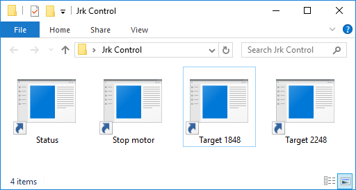 |
A folder with shortcuts to jrk2cmd that could be used for controlling the Jrk G2. |
|---|
The Jrk G2 Command-line Utility (jrk2cmd) provides many commands for controlling the Jrk G2, and gets installed along with the rest of the Jrk software and drivers. After installing jrk2cmd as described in Section 3.1, you can follow these instructions to make a shortcut to it:
- Right-click on the blank area of your desktop or any other folder, open the “New” menu, and select “Shortcut”.
- Windows will open a “Create Shortcut” wizard and prompt you for the location of the item you want to make a shortcut to. Type
jrk2cmd --clear-errors --target 2248 --pause-on-erroror any other command you want to run. - Click “Next”. If Windows says “The file jrk2cmd cannot be found.”, it either means you have not installed the Jrk software, or the folder containing
jrk2cmd.exeis not listed in your PATH environment variable (maybe you unchecked the checkbox that adds it your PATH when installing the software). As a solution, you could replacejrk2cmdin the input box with the full path tojrk2cmd.exein double quotes. However, the easiest solution is probably to reinstall the Jrk software, making sure to leave the “Add the bin directory to the PATH environment variable.” checkbox checked this time. You might also need to restart your computer. - Type an appropriate name for your shortcut and click “Finish”.
Now you should be able to double-click on your shortcut to run the command you entered. You will probably see a black window briefly flash on the screen run the command runs.
At this point, you might get an error message that says:
Error: Failed to open generic handle. Access is denied. Try closing all other programs that are using the device. Windows error code 0x5.
It is best to follow the advice in the error message and close the Jrk G2 Configuration Utility and any other programs that might be using the Jrk. In Windows, only one program can use the Jrk’s native USB interface at a time.
Example commands
Here are some example commands you might want to put into a shortcut, along with information about how the command works:
jrk2cmd --clear-errors --target 1234 --pause-on-error
The command above will clear any latched errors and set the Jrk’s target to 1234. The Jrk’s input mode should be set to “Serial / I²C / USB” for this command to work. The --pause-on-error option means that if there are any errors communicating with the Jrk, then jrk2cmd will keep running until you press Enter or close the window. This prevents the jrk2cmd output window from closing immediately and allows you to read the error message. However, if there are some errors that are still happening on the Jrk and could not be cleared, there will be no notification.
jrk2cmd --stop --pause-on-error
The command above sends a “Stop motor” command. You can find more details about this command in Section 11. As in the previous command, --pause-on-error gives you a chance to see error messages if there is any problem communicating with the Jrk.
jrk2cmd --status --pause
The command above shows status information from the Jrk. This can be useful for seeing what errors are happening on the Jrk or seeing the target and feedback values. You can add the --full option to see more information. The --pause option tells jrk2cmd to always wait for you to press Enter or close the window before terminating, which gives you a chance to see the output. By default, the jrk2cmd console window will not have enough lines to show the full status output all at once. To fix this, you can modify the shortcut to make the console have more lines: right-click on the shortcut, select “Properties”, select the “Layout” tab, and then in the “Window Size” box change the “Height”.
Multiple Jrk G2 devices
If you have multiple Jrk G2 devices connected to the computer via USB, you will need to add the -d option to each shortcut in order to specify the serial number of the device you want to use. For example, a shortcut that gets the status of the Jrk G2 with serial number 12345678 would have a command like jrk2cmd -d 12345678 --status --pause. You can see your Jrk’s serial number in the Jrk G2 Configuration Utility or by running jrk2cmd --list.
Multiple commands in one shortcut
You can specify multiple commands to the Jrk in one shortcut by just adding more options. For example, you could temporarily change the Jrk’s maximum duty cycle and set the target at the same time with a command like jrk2cmd --max-duty-cycle 300 --target 1234 --pause-on-error. The order of the options does not matter; the utility performs the commands in a predetermined order. If you need something a bit more complicated, you might consider writing a Batch or PowerShell script.
Shortcut customizations
In the Properties dialog for a shortcut, you can change its icon or assign a shortcut key. You can add shortcuts to your Start Menu or make a toolbar of shortcuts inside the taskbar for quick access.
15.5. Example serial code for Linux and macOS in C
The example C code below uses parts of the POSIX API provided by Linux and macOS to communicate with a Jrk G2 via serial. It demonstrates how to set the target of the Jrk by sending a “Set target” command and how to read variables using a “Get variables” command. For a very similar example that only works on Windows, see Section 15.6.
The Jrk’s input mode should be set to “Serial / I2C / USB”, or else the “Set target” command will not work. Also, you might need to change the const char * device line in the code that specifies what serial port to connect to.
If the Jrk is connected to your PC via USB, you will need to set the Jrk’s serial mode to “USB dual port” in the “Input” tab of the Jrk G2 Configuration Utility. The baud rate specified in this code and in the Jrk’s settings do not have to match because the serial bytes are transferred via USB. (You could remove the code that sets the baud rate.) Also, instead of using this code, you might consider running the Jrk G2 Command-line Utility (jrk2cmd), which uses the native USB interface, since it can take care of all of the low-level details of communication for you.
If the Jrk is connected via its RX and TX lines, you will need to set the Jrk’s serial mode to “UART” and select the baud rate you want to use in the “Input” tab of the Jrk G2 Configuration Utility. The baud rate you select in the code should match the baud rate specified in the configuration utility. The code below only supports certain standard baud rates: 4800, 9600, 19200, 38400, 115200. Due to hardware limitations, the Jrk cannot exactly produce 38400 baud or 115200 baud, but it can use similar baud rates that are close enough to work.
// Uses POSIX serial port functions to send and receive data from a Jrk G2.
// NOTE: The Jrk's input mode must be "Serial / I2C / USB".
// NOTE: The Jrk's serial mode must be set to "USB dual port" if you are
//   connecting to it directly via USB.
// NODE: The Jrk's serial mode must be set to "UART" if you are connecting to
//   it via is TX and RX lines.
// NOTE: You might need to change the 'const char * device' line below to
//   specify the correct serial port.

#include <fcntl.h>
#include <stdio.h>
#include <unistd.h>
#include <stdint.h>
#include <termios.h>

// Opens the specified serial port, sets it up for binary communication,
// configures its read timeouts, and sets its baud rate.
// Returns a non-negative file descriptor on success, or -1 on failure.
int open_serial_port(const char * device, uint32_t baud_rate)
{
  int fd = open(device, O_RDWR | O_NOCTTY);
  if (fd == -1)
  {
    perror(device);
    return -1;
  }

  // Flush away any bytes previously read or written.
  int result = tcflush(fd, TCIOFLUSH);
  if (result)
  {
    perror("tcflush failed");  // just a warning, not a fatal error
  }

  // Get the current configuration of the serial port.
  struct termios options;
  result = tcgetattr(fd, &options);
  if (result)
  {
    perror("tcgetattr failed");
    close(fd);
    return -1;
  }

  // Turn off any options that might interfere with our ability to send and
  // receive raw binary bytes.
  options.c_iflag &= ~(INLCR | IGNCR | ICRNL | IXON | IXOFF);
  options.c_oflag &= ~(ONLCR | OCRNL);
  options.c_lflag &= ~(ECHO | ECHONL | ICANON | ISIG | IEXTEN);

  // Set up timeouts: Calls to read() will return as soon as there is
  // at least one byte available or when 100 ms has passed.
  options.c_cc[VTIME] = 1;
  options.c_cc[VMIN] = 0;

  // This code only supports certain standard baud rates. Supporting
  // non-standard baud rates should be possible but takes more work.
  switch (baud_rate)
  {
  case 4800:   cfsetospeed(&options, B4800);   break;
  case 9600:   cfsetospeed(&options, B9600);   break;
  case 19200:  cfsetospeed(&options, B19200);  break;
  case 38400:  cfsetospeed(&options, B38400);  break;
  case 115200: cfsetospeed(&options, B115200); break;
  default:
    fprintf(stderr, "warning: baud rate %u is not supported, using 9600.\n",
      baud_rate);
    cfsetospeed(&options, B9600);
    break;
  }
  cfsetispeed(&options, cfgetospeed(&options));

  result = tcsetattr(fd, TCSANOW, &options);
  if (result)
  {
    perror("tcsetattr failed");
    close(fd);
    return -1;
  }

  return fd;
}

// Writes bytes to the serial port, returning 0 on success and -1 on failure.
int write_port(int fd, uint8_t * buffer, size_t size)
{
  ssize_t result = write(fd, buffer, size);
  if (result != (ssize_t)size)
  {
    perror("failed to write to port");
    return -1;
  }
  return 0;
}

// Reads bytes from the serial port.
// Returns after all the desired bytes have been read, or if there is a
// timeout or other error.
// Returns the number of bytes successfully read into the buffer, or -1 if
// there was an error reading.
ssize_t read_port(int fd, uint8_t * buffer, size_t size)
{
  size_t received = 0;
  while (received < size)
  {
    ssize_t r = read(fd, buffer + received, size - received);
    if (r < 0)
    {
      perror("failed to read from port");
      return -1;
    }
    if (r == 0)
    {
      // Timeout
      break;
    }
    received += r;
  }
  return received;
}

// Sets the target, returning 0 on success and -1 on failure.
//
// For more information about what this command does, see the "Set Target"
// command in the "Command reference" section of the Jrk G2 user's guide.
int jrk_set_target(int fd, uint16_t target)
{
  if (target > 4095) { target = 4095; }
  uint8_t command[2];
  command[0] = 0xC0 + (target & 0x1F);
  command[1] = (target >> 5) & 0x7F;
  return write_port(fd, command, sizeof(command));
}

// Gets one or more variables from the Jrk (without clearing them).
// Returns 0 for success, -1 for failure.
int jrk_get_variable(int fd, uint8_t offset, uint8_t * buffer, uint8_t length)
{
  uint8_t command[] = { 0xE5, offset, length };
  int result = write_port(fd, command, sizeof(command));
  if (result) { return -1; }
  ssize_t received = read_port(fd, buffer, length);
  if (received < 0) { return -1; }
  if (received != length)
  {
    fprintf(stderr, "read timeout: expected %u bytes, got %zu\n",
      length, received);
    return -1;
  }
  return 0;
}

// Gets the Target variable from the jrk or returns -1 on failure.
int jrk_get_target(int fd)
{
  uint8_t buffer[2];
  int result = jrk_get_variable(fd, 0x02, buffer, sizeof(buffer));
  if (result) { return -1; }
  return buffer[0] + 256 * buffer[1];
}

// Gets the Feedback variable from the jrk or returns -1 on failure.
int jrk_get_feedback(int fd)
{
  // 0x04 is the offset of the feedback variable in the "Variable reference"
  // section of the Jrk user's guide.  The variable is two bytes long.
  uint8_t buffer[2];
  int result = jrk_get_variable(fd, 0x04, buffer, sizeof(buffer));
  if (result) { return -1; }
  return buffer[0] + 256 * buffer[1];
}

int main()
{
  // Choose the serial port name.  If the Jrk is connected directly via USB,
  // you can run "jrk2cmd --cmd-port" to get the right name to use here.
  // Linux USB example:          "/dev/ttyACM0"  (see also: /dev/serial/by-id)
  // macOS USB example:          "/dev/cu.usbmodem001234562"
  // Cygwin example:             "/dev/ttyS7"
  const char * device = "/dev/ttyACM0";

  // Choose the baud rate (bits per second).  This does not matter if you are
  // connecting to the Jrk over USB.  If you are connecting via the TX and RX
  // lines, this should match the baud rate in the Jrk's serial settings.
  uint32_t baud_rate = 9600;

  int fd = open_serial_port(device, baud_rate);
  if (fd < 0) { return 1; }

  int feedback = jrk_get_feedback(fd);
  if (feedback < 0) { return 1; }

  printf("Feedback is %d.\n", feedback);

  int target = jrk_get_target(fd);
  if (target < 0) { return 1; }
  printf("Target is %d.\n", target);

  int new_target = (target < 2048) ? 2248 : 1848;
  printf("Setting target to %d.\n", new_target);
  int result = jrk_set_target(fd, new_target);
  if (result) { return 1; }

  close(fd);
  return 0;
}
15.6. Example serial code for Windows in C
The example C code below uses the Windows API to communicate with a Jrk G2 via serial. It demonstrates how to set the target of the Jrk by sending a “Set target” command and how to read variables using a “Get variables” command. For a very similar example that works on Linux and macOS, see Section 15.5.
The Jrk’s input mode should be set to “Serial / I2C / USB”, or else the “Set target” command will not work. Also, you will need to change the const char * device line in the code that specifies what serial port to connect to.
If the Jrk is connected to your PC via USB, you will need to set the Jrk’s serial mode to “USB dual port” in the “Input” tab of the Jrk G2 Configuration Utility. The baud rate specified in this code and in the Jrk’s settings do not have to match because the serial bytes are transferred via USB. (You could remove the code that sets the baud rate.) Also, instead of using this code, you might consider running the Jrk G2 Command-line Utility (jrk2cmd), which uses the native USB interface, since it can take care of all of the low-level details of communication for you.
If the Jrk is connected via its RX and TX lines, you will need to set the Jrk’s serial mode to “UART” and select the baud rate you want to use in the “Input” tab of the Jrk G2 Configuration Utility. The baud rate in the code should match the baud rate specified in the configuration utility.
// Uses Windows API serial port functions to send and receive data from a
// Jrk G2.
// NOTE: The Jrk's input mode must be "Serial / I2C / USB".
// NOTE: The Jrk's serial mode must be set to "USB dual port" if you are
//   connecting to it directly via USB.
// NODE: The Jrk's serial mode must be set to "UART" if you are connecting to
//   it via is TX and RX lines.
// NOTE: You need to change the 'const char * device' line below to
//   specify the correct serial port.

#include <stdio.h>
#include <stdint.h>
#include <windows.h>

void print_error(const char * context)
{
  DWORD error_code = GetLastError();
  char buffer[256];
  DWORD size = FormatMessageA(
    FORMAT_MESSAGE_FROM_SYSTEM | FORMAT_MESSAGE_MAX_WIDTH_MASK,
    NULL, error_code, MAKELANGID(LANG_ENGLISH, SUBLANG_ENGLISH_US),
    buffer, sizeof(buffer), NULL);
  if (size == 0) { buffer[0] = 0; }
  fprintf(stderr, "%s: %s\n", context, buffer);
}

// Opens the specified serial port, configures its timeouts, and sets its
// baud rate.  Returns a handle on success, or INVALID_HANDLE_VALUE on failure.
HANDLE open_serial_port(const char * device, uint32_t baud_rate)
{
  HANDLE port = CreateFileA(device, GENERIC_READ | GENERIC_WRITE, 0, NULL,
    OPEN_EXISTING, FILE_ATTRIBUTE_NORMAL, NULL);
  if (port == INVALID_HANDLE_VALUE)
  {
    print_error(device);
    return INVALID_HANDLE_VALUE;
  }

  // Flush away any bytes previously read or written.
  BOOL success = FlushFileBuffers(port);
  if (!success)
  {
    print_error("Failed to flush serial port");
    CloseHandle(port);
    return INVALID_HANDLE_VALUE;
  }

  // Configure read and write operations to time out after 100 ms.
  COMMTIMEOUTS timeouts = {0};
  timeouts.ReadIntervalTimeout = 0;
  timeouts.ReadTotalTimeoutConstant = 100;
  timeouts.ReadTotalTimeoutMultiplier = 0;
  timeouts.WriteTotalTimeoutConstant = 100;
  timeouts.WriteTotalTimeoutMultiplier = 0;

  success = SetCommTimeouts(port, &timeouts);
  if (!success)
  {
    print_error("Failed to set serial timeouts");
    CloseHandle(port);
    return INVALID_HANDLE_VALUE;
  }

  // Set the baud rate and other options.
  DCB state = {0};
  state.DCBlength = sizeof(DCB);
  state.BaudRate = baud_rate;
  state.ByteSize = 8;
  state.Parity = NOPARITY;
  state.StopBits = ONESTOPBIT;
  success = SetCommState(port, &state);
  if (!success)
  {
    print_error("Failed to set serial settings");
    CloseHandle(port);
    return INVALID_HANDLE_VALUE;
  }

  return port;
}

// Writes bytes to the serial port, returning 0 on success and -1 on failure.
int write_port(HANDLE port, uint8_t * buffer, size_t size)
{
  DWORD written;
  BOOL success = WriteFile(port, buffer, size, &written, NULL);
  if (!success)
  {
    print_error("Failed to write to port");
    return -1;
  }
  if (written != size)
  {
    print_error("Failed to write all bytes to port");
    return -1;
  }
  return 0;
}

// Reads bytes from the serial port.
// Returns after all the desired bytes have been read, or if there is a
// timeout or other error.
// Returns the number of bytes successfully read into the buffer, or -1 if
// there was an error reading.
SSIZE_T read_port(HANDLE port, uint8_t * buffer, size_t size)
{
  DWORD received;
  BOOL success = ReadFile(port, buffer, size, &received, NULL);
  if (!success)
  {
    print_error("Failed to read from port");
    return -1;
  }
  return received;
}

// Sets the target, returning 0 on success and -1 on failure.
//
// For more information about what this command does, see the "Set Target"
// command in the "Command reference" section of the Jrk G2 user's guide.
int jrk_set_target(HANDLE port, uint16_t target)
{
  if (target > 4095) { target = 4095; }
  uint8_t command[2];
  command[0] = 0xC0 + (target & 0x1F);
  command[1] = (target >> 5) & 0x7F;
  return write_port(port, command, sizeof(command));
}

// Gets one or more variables from the Jrk (without clearing them).
// Returns 0 for success, -1 for failure.
int jrk_get_variable(HANDLE port, uint8_t offset, uint8_t * buffer,
  uint8_t length)
{
  uint8_t command[] = { 0xE5, offset, length };
  int result = write_port(port, command, sizeof(command));
  if (result) { return -1; }
  SSIZE_T received = read_port(port, buffer, length);
  if (received < 0) { return -1; }
  if (received != length)
  {
    fprintf(stderr, "read timeout: expected %u bytes, got %lld\n",
      length, (int64_t)received);
    return -1;
  }
  return 0;
}

// Gets the Target variable from the jrk or returns -1 on failure.
int jrk_get_target(HANDLE port)
{
  uint8_t buffer[2];
  int result = jrk_get_variable(port, 0x02, buffer, sizeof(buffer));
  if (result) { return -1; }
  return buffer[0] + 256 * buffer[1];
}

// Gets the Feedback variable from the jrk or returns -1 on failure.
int jrk_get_feedback(HANDLE port)
{
  // 0x04 is the offset of the feedback variable in the "Variable reference"
  // section of the Jrk user's guide.  The variable is two bytes long.
  uint8_t buffer[2];
  int result = jrk_get_variable(port, 0x04, buffer, sizeof(buffer));
  if (result) { return -1; }
  return buffer[0] + 256 * buffer[1];
}

int main()
{
  // Choose the serial port name.  If the Jrk is connected directly via USB,
  // you can run "jrk2cmd --cmd-port" to get the right name to use here.
  // COM ports higher than COM9 need the \\.\ prefix, which is written as
  // "\\\\.\\" in C because we need to escape the backslashes.
  const char * device = "\\\\.\\COM7";

  // Choose the baud rate (bits per second).  This does not matter if you are
  // connecting to the Jrk over USB.  If you are connecting via the TX and RX
  // lines, this should match the baud rate in the Jrk's serial settings.
  uint32_t baud_rate = 9600;

  HANDLE port = open_serial_port(device, baud_rate);
  if (port == INVALID_HANDLE_VALUE) { return 1; }

  int feedback = jrk_get_feedback(port);
  if (feedback < 0) { return 1; }

  printf("Feedback is %d.\n", feedback);

  int target = jrk_get_target(port);
  if (target < 0) { return 1; }
  printf("Target is %d.\n", target);

  int new_target = (target < 2048) ? 2248 : 1848;
  printf("Setting target to %d.\n", new_target);
  int result = jrk_set_target(port, new_target);
  if (result) { return 1; }

  CloseHandle(port);
  return 0;
}
15.7. Example serial code in Python
The example Python code below uses the pySerial library to communicate with the Jrk G2 via serial. It demonstrates how to set the target of the Jrk by sending a “Set target” command and how to read variables using a “Get variables” command.
The Jrk’s input mode should be set to “Serial / I2C / USB”, or else the “Set target” command will not work. Also, you might need to change the line that sets port_name in order to specify the correct serial port.
If the Jrk is connected to your PC via USB, you will need to set the Jrk’s serial mode to “USB dual port” in the “Input” tab of the Jrk G2 Configuration Utility. The baud rate specified in this code and in the Jrk’s settings do not have to match because the serial bytes are transferred via USB. Also, instead of using this code, you might consider running the Jrk G2 Command-line Utility (jrk2cmd), which uses the native USB interface, since it can take care of all of the low-level details of communication for you (see Section 15.3).
If the Jrk is connected via its RX and TX lines, you will need to set the Jrk’s serial mode to “UART” and select the baud rate you want to use in the “Input” tab of the Jrk G2 Configuration Utility. The baud rate in the code should match the baud rate specified in the configuration utility.
If you run the code and get the error “ImportError: No module named serial” or “ModuleNotFoundError: No module named ‘serial’”, it means that the pySerial library is not installed, and you should follow the instructions in the pySerial documentation to install it.
# Uses the pySerial library to send and receive data from a Jrk G2.
#
# NOTE: The Jrk's input mode must be "Serial / I2C / USB".
# NOTE: You might need to change the "port_name =" line below to specify the
#   right serial port.

import serial

class JrkG2Serial(object):
  def __init__(self, port, device_number=None):
    self.port = port
    self.device_number = device_number

  def send_command(self, cmd, *data_bytes):
    if self.device_number == None:
      header = [cmd]  # Compact protocol
    else:
      header = [0xAA, device_number, cmd & 0x7F]  # Pololu protocol
    self.port.write(bytes(header + list(data_bytes)))

  # Sets the target.  For more information about what this command does,
  # see the "Set Target" command in the "Command reference" section of
  # the Jrk G2 user's guide.
  def set_target(self, target):
    self.send_command(0xC0 + (target & 0x1F), (target >> 5) & 0x7F)

  # Gets one or more variables from the Jrk (without clearing them).
  def get_variables(self, offset, length):
    self.send_command(0xE5, offset, length)
    result = self.port.read(length)
    if len(result) != length:
      raise RuntimeError("Expected to read {} bytes, got {}."
        .format(length, len(result)))
    return bytearray(result)

  # Gets the Target variable from the Jrk.
  def get_target(self):
    b = self.get_variables(0x02, 2)
    return b[0] + 256 * b[1]

  # Gets the Feedback variable from the Jrk.
  def get_feedback(self):
    b = self.get_variables(0x04, 2)
    return b[0] + 256 * b[1]

# Choose the serial port name.  If the Jrk is connected directly via USB,
# you can run "jrk2cmd --cmd-port" to get the right name to use here.
# Linux USB example:  "/dev/ttyACM0"
# macOS USB example:  "/dev/cu.usbmodem001234562"
# Windows example:    "COM6"
port_name = "/dev/ttyACM0"

# Choose the baud rate (bits per second).  This does not matter if you are
# connecting to the Jrk over USB.  If you are connecting via the TX and RX
# lines, this should match the baud rate in the Jrk's serial settings.
baud_rate = 9600

# Change this to a number between 0 and 127 that matches the device number of
# your Jrk if there are multiple serial devices on the line and you want to
# use the Pololu Protocol.
device_number = None

port = serial.Serial(port_name, baud_rate, timeout=0.1, write_timeout=0.1)

jrk = JrkG2Serial(port, device_number)

feedback = jrk.get_feedback()
print("Feedback is {}.".format(feedback))

target = jrk.get_target()
print("Target is {}.".format(target))

new_target = 2248 if target < 2048 else 1848
print("Setting target to {}.".format(new_target))
jrk.set_target(new_target)
15.8. Example I²C code for Linux in C
The example C code below uses the I²C API provided by the Linux kernel to send and receive data from a Jrk G2. It demonstrates how to set the target of the Jrk by sending a “Set target” command and how to read variables using a “Get variables” command. This code only works on Linux.
If you are using a Raspberry Pi, please note that the Raspberry Pi’s hardware I²C module has a bug that causes this code to not work reliably. As a workaround, we recommend enabling the i2c-gpio overlay and using the I²C device that it provides. To do this, add the line dtoverlay=i2c-gpio to /boot/config.txt and reboot. The overlay documentation has information about the parameters you can put on that line, but those parameters are not required. Connect the Jrk’s SDA line to GPIO23 and connect the Jrk’s SCL line to GPIO24. The i2c-gpio overlay creates a new I²C device which is usually named /dev/i2c-3, and the code below uses that device. To give your user permission to access I²C busses without being root, you might have to add yourself to the i2c group by running sudo usermod -a -G i2c $(whoami) and restarting.
// Uses the Linux I2C API to send and receive data from a Jrk G2.
// NOTE: The Jrk's input mode must be "Serial / I2C / USB".
// NOTE: For reliable operation on a Raspberry Pi, enable the i2c-gpio
//   overlay and use the I2C device it provides (usually /dev/i2c-3).
// NOTE: You might need to change the 'const char * device' line below
//   to specify the correct I2C device.
// NOTE: You might need to change the `const uint8_t address' line below
// to match the device number of your Jrk.

#include <fcntl.h>
#include <linux/i2c.h>
#include <linux/i2c-dev.h>
#include <stdint.h>
#include <stdio.h>
#include <sys/ioctl.h>
#include <unistd.h>

// Opens the specified I2C device.  Returns a non-negative file descriptor
// on success, or -1 on failure.
int open_i2c_device(const char * device)
{
  int fd = open(device, O_RDWR);
  if (fd == -1)
  {
    perror(device);
    return -1;
  }
  return fd;
}

// Sets the target, returning 0 on success and -1 on failure.
//
// For more information about what this command does, see the "Set Target"
// command in the "Command reference" section of the Jrk G2 user's guide.
int jrk_set_target(int fd, uint8_t address, uint16_t target)
{
  uint8_t command[] = {
    (uint8_t)(0xC0 + (target & 0x1F)),
    (uint8_t)((target >> 5) & 0x7F),
  };
  struct i2c_msg message = { address, 0, sizeof(command), command };
  struct i2c_rdwr_ioctl_data ioctl_data = { &message, 1 };
  int result = ioctl(fd, I2C_RDWR, &ioctl_data);
  if (result != 1)
  {
    perror("failed to set target");
    return -1;
  }
  return 0;
}

// Gets one or more variables from the Jrk (without clearing them).
// Returns 0 for success, -1 for failure.
int jrk_get_variable(int fd, uint8_t address, uint8_t offset,
  uint8_t * buffer, uint8_t length)
{
  uint8_t command[] = { 0xE5, offset };
  struct i2c_msg messages[] = {
    { address, 0, sizeof(command), command },
    { address, I2C_M_RD, length, buffer },
  };
  struct i2c_rdwr_ioctl_data ioctl_data = { messages, 2 };
  int result = ioctl(fd, I2C_RDWR, &ioctl_data);
  if (result != 2)
  {
    perror("failed to get variables");
    return -1;
  }
  return 0;
}

// Gets the Target variable from the jrk or returns -1 on failure.
int jrk_get_target(int fd, uint8_t address)
{
  uint8_t buffer[2];
  int result = jrk_get_variable(fd, address, 0x02, buffer, sizeof(buffer));
  if (result) { return -1; }
  return buffer[0] + 256 * buffer[1];
}

// Gets the Feedback variable from the jrk or returns -1 on failure.
int jrk_get_feedback(int fd, uint8_t address)
{
  // 0x04 is the offset of the feedback variable in the "Variable reference"
  // section of the Jrk user's guide.  The variable is two bytes long.
  uint8_t buffer[2];
  int result = jrk_get_variable(fd, address, 0x04, buffer, sizeof(buffer));
  if (result) { return -1; }
  return buffer[0] + 256 * buffer[1];
}

int main()
{
  // Choose the I2C device.
  const char * device = "/dev/i2c-3";

  // Set the I2C address of the Jrk (the device number).
  const uint8_t address = 11;

  int fd = open_i2c_device(device);
  if (fd < 0) { return 1; }

  int feedback = jrk_get_feedback(fd, address);
  if (feedback < 0) { return 1; }
  printf("Feedback is %d.\n", feedback);

  int target = jrk_get_target(fd, address);
  if (target < 0) { return 1; }
  printf("Target is %d.\n", target);

  int new_target = (target < 2048) ? 2248 : 1848;
  printf("Setting target to %d.\n", new_target);
  int result = jrk_set_target(fd, address, new_target);
  if (result) { return 1; }

  close(fd);
  return 0;
}
15.9. Example I²C code for Linux in Python
The example code below uses a Python library named smbus2 to send and receive data from a Jrk G2 via I²C. It demonstrates how to set the target of the Jrk by sending a “Set target” command and how to read variables using a “Get variables” command. This example works on Linux with either Python 2 or Python 3. This example is very similar to the example in Section 15.8, except that it uses Python instead of C.
If you are using a Raspberry Pi, please see the notes about setting up I²C for the Raspberry Pi in Section 15.8.
To install the smbus2 library, you will need to run either pip install smbus2 or pip3 install smbus2 depending on what version of Python you want to use and what Linux distribution you are using. On Raspbian, pip is for Python 2 and pip3 is for Python 3.
# Uses the smbus2 library to send and receive data from a Jrk G2.
# Works on Linux with either Python 2 or Python 3.
#
# NOTE: The Jrk's input mode must be "Serial / I2C / USB".
# NOTE: For reliable operation on a Raspberry Pi, enable the i2c-gpio
#   overlay and use the I2C device it provides (usually /dev/i2c-3).
# NOTE: You might nee to change the 'SMBus(3)' line below to specify the
#   correct I2C device.
# NOTE: You might need to change the 'address = 11' line below to match
#   the device number of your Jrk.

from smbus2 import SMBus, i2c_msg

class JrkG2I2C(object):
  def __init__(self, bus, address):
    self.bus = bus
    self.address = address

  # Sets the target.  For more information about what this command does,
  # see the "Set Target" command in the "Command reference" section of
  # the Jrk G2 user's guide.
  def set_target(self, target):
    command = [0xC0 + (target & 0x1F), (target >> 5) & 0x7F]
    write = i2c_msg.write(self.address, command)
    self.bus.i2c_rdwr(write)

  # Gets one or more variables from the Jrk (without clearing them).
  # Returns a list of byte values (integers between 0 and 255).
  def get_variables(self, offset, length):
    write = i2c_msg.write(self.address, [0xE5, offset])
    read = i2c_msg.read(self.address, length)
    self.bus.i2c_rdwr(write, read)
    return list(read)

  # Gets the Target variable from the Jrk.
  def get_target(self):
    b = self.get_variables(0x02, 2)
    return b[0] + 256 * b[1]

  # Gets the Feedback variable from the Jrk.
  def get_feedback(self):
    b = self.get_variables(0x04, 2)
    return b[0] + 256 * b[1]

# Open a handle to "/dev/i2c-3", representing the I2C bus.
bus = SMBus(3)

# Select the I2C address of the Jrk (the device number).
address = 11

jrk = JrkG2I2C(bus, address)

feedback = jrk.get_feedback()
print("Feedback is {}.".format(feedback))

target = jrk.get_target()
print("Target is {}.".format(target))

new_target = 2248 if target < 2048 else 1848
print("Setting target to {}.".format(new_target))
jrk.set_target(new_target)
15.10. Example I²C code for MicroPython
The example code below uses the machine.I2C class in MicroPython to send and receive data from a Jrk G2 via I²C. It demonstrates how to set the target of the Jrk by sending a “Set target” command and how to read variables using a “Get variables” command. This example is designed to run on the Raspberry Pi Pico and can be ported to other boards by changing the line at the top that sets up the i2c object.
from machine import I2C, Pin

i2c = I2C(0, sda=Pin(8), scl=Pin(9), freq=400000)

class JrkG2I2C(object):
  def __init__(self, address):
    self.address = address

  # Sets the target.  For more information about what this command does,
  # see the "Set Target" command in the "Command reference" section of
  # the Jrk G2 user's guide.
  def set_target(self, target):
    command = [0xC0 + (target & 0x1F), (target >> 5) & 0x7F]
    i2c.writeto(self.address, bytes(command))

  # Gets one or more variables from the Jrk (without clearing them).
  # Returns a bytes object.
  def get_variables(self, offset, length):
    i2c.writeto(self.address, bytes([0xE5, offset]))
    return i2c.readfrom(self.address, length)

  # Gets the Target variable from the Jrk.
  def get_target(self):
    b = self.get_variables(0x02, 2)
    return b[0] + 256 * b[1]

  # Gets the Feedback variable from the Jrk.
  def get_feedback(self):
    b = self.get_variables(0x04, 2)
    return b[0] + 256 * b[1]

# Select the I2C address of the Jrk (the device number).
address = 11

jrk = JrkG2I2C(address)

feedback = jrk.get_feedback()
print("Feedback is {}.".format(feedback))

target = jrk.get_target()
print("Target is {}.".format(target))

new_target = 2248 if target < 2048 else 1848
print("Setting target to {}.".format(new_target))
jrk.set_target(new_target)
Related products


Home | Forum | Blog | Support | Ordering Information | Lists | Distributors | BIG Order Form | About | Contact
© 2001–2026 Pololu Corporation
