View document on multiple pages.
You can also view this document as a printable PDF.
- 1. Overview
- 2. Contacting Pololu
- 3. Contents and additional components
- 4. Assembling the Romi Chassis
- 5. Power options
- 6. Dimensions and mounting holes
- 7. Next steps
1. Overview
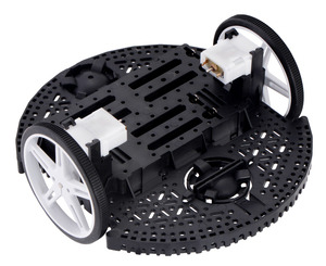
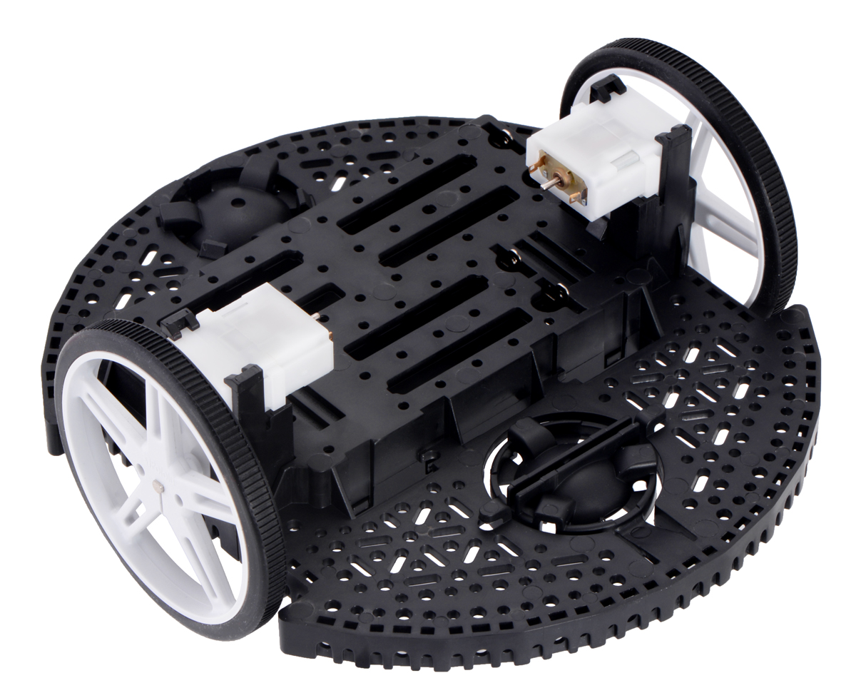
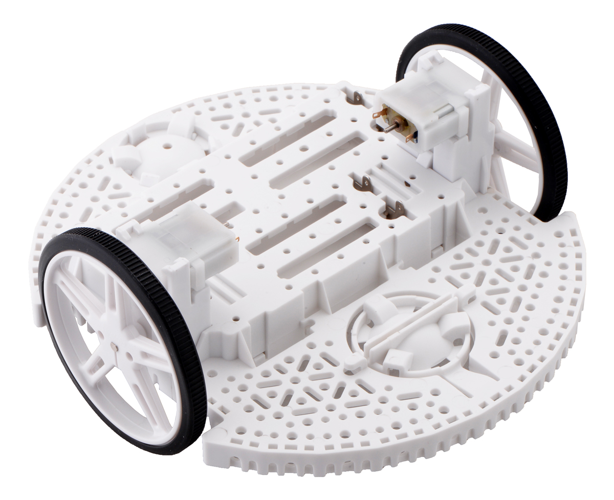
The Romi chassis is a differential-drive mobile robot platform with a diameter of 6.5″ (165 mm) and an integrated battery holder for six AA batteries. The drive wheels are located on a diameter of the circular base plate, allowing for turns or spinning in place. A large, fixed ball caster in the rear provides a smooth third point of contact, and a second ball caster can optionally be added to the front. The chassis uses 70×8mm Pololu wheels and Mini Plastic Gearmotors with extended backshafts to enable quadrature encoders for position feedback.
The Romi chassis has an abundance of general-purpose mounting holes and slots intended for various sizes of screws (not included) such as #2-56, #4-40, M2, and M3. These holes can be used for mounting your electronics, such as your microcontroller, motor drivers, and sensors.
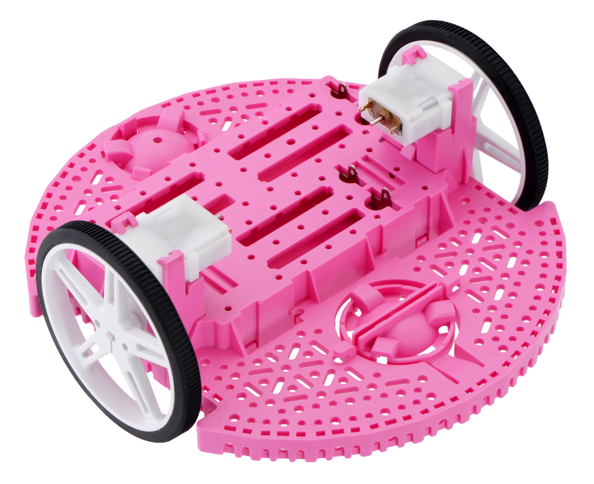
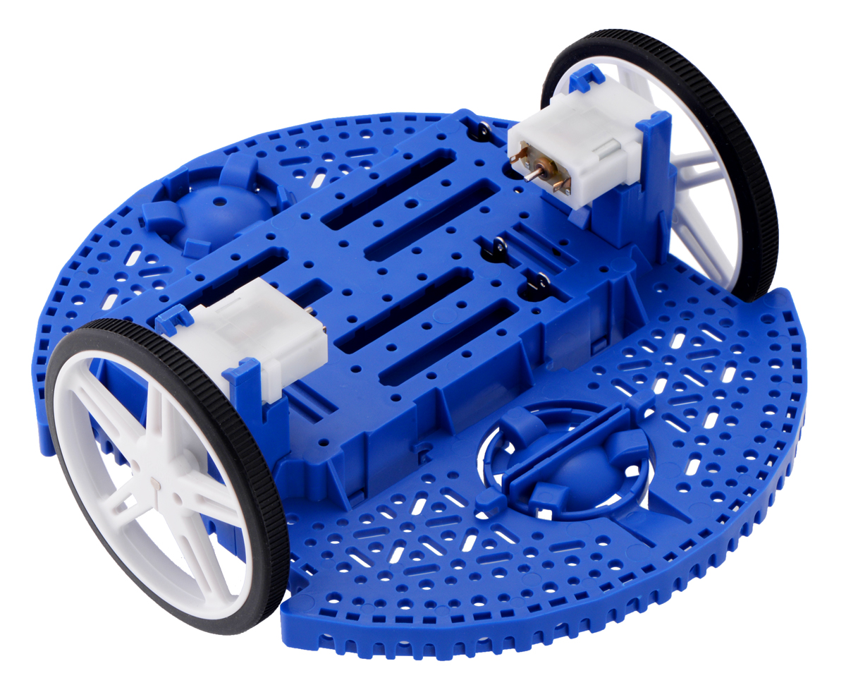
The plastic components making up the chassis are available in six colors, either individually or in kits that include motors and battery contacts.
2. Contacting Pololu
We would be delighted to hear from you about any of your projects and about your experience with the Romi Chassis. You can contact us directly or post on our forum. Tell us what we did well, what we could improve, what you would like to see in the future, or anything else you would like to say!
3. Contents and additional components
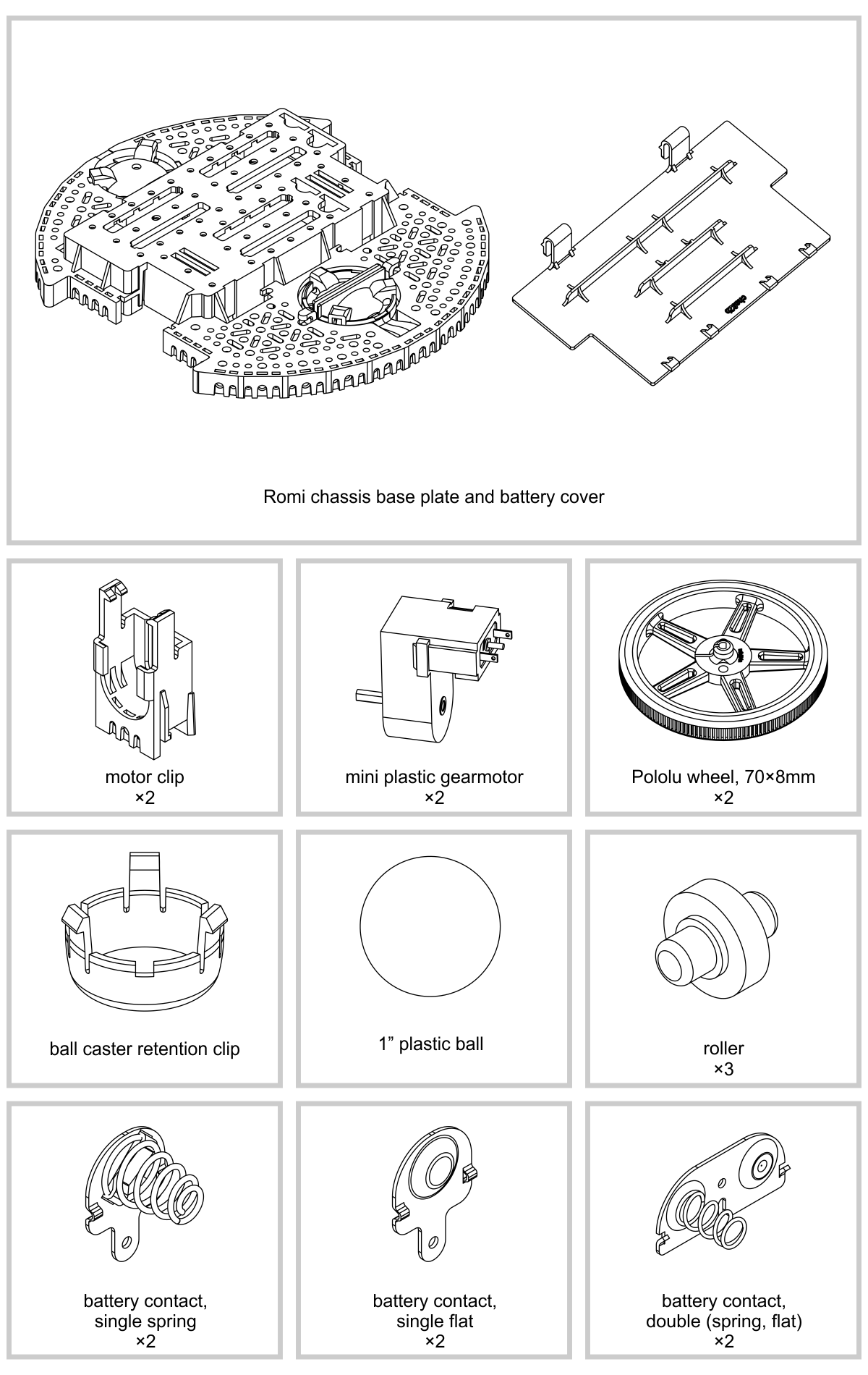
Kit contents
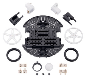 |
Contents of the Romi Chassis Kit – Black. |
|---|
The Romi Chassis Kit includes the following items:
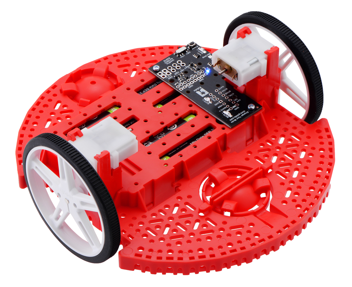
The Romi Chassis Kit is available in black, pink, red, yellow, blue, and white. The individual components are also available individually for replacement parts or to make custom color combinations.
Additional things you will need
You will likely also need a soldering iron for connecting your motors and batteries to your electronics.
Optional components to consider
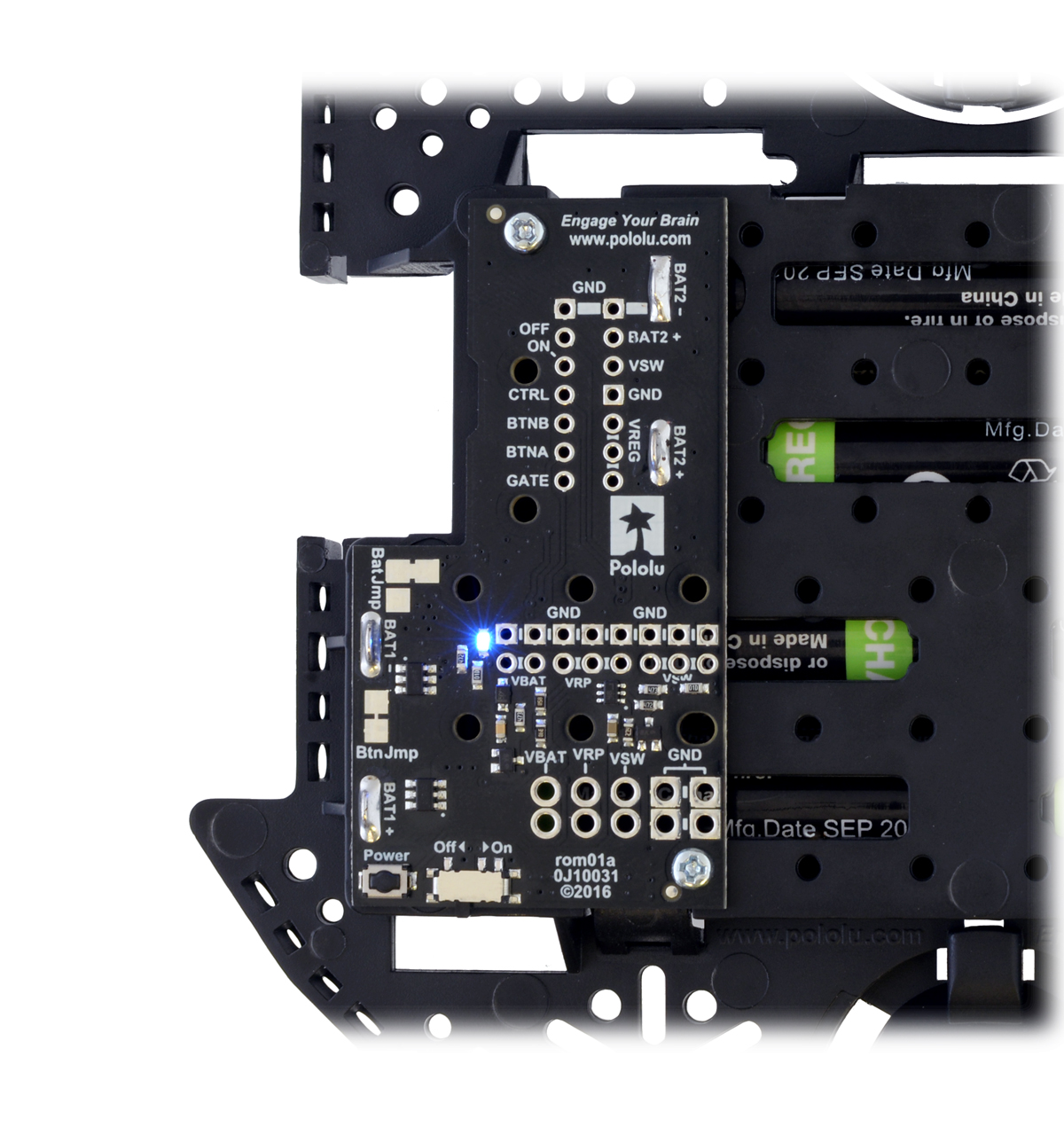
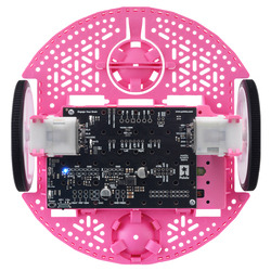
- Power Distribution Board for Romi Chassis – This board helps you get your Romi chassis running quickly. It solders to the chassis’s battery contacts and provides reverse battery protection, several power switching options, and convenient access to the various power busses.
 | Power Distribution Board for Romi Chassis on a black chassis. |
|---|
|
 | Power Distribution Board for Romi Chassis. |
|---|
|
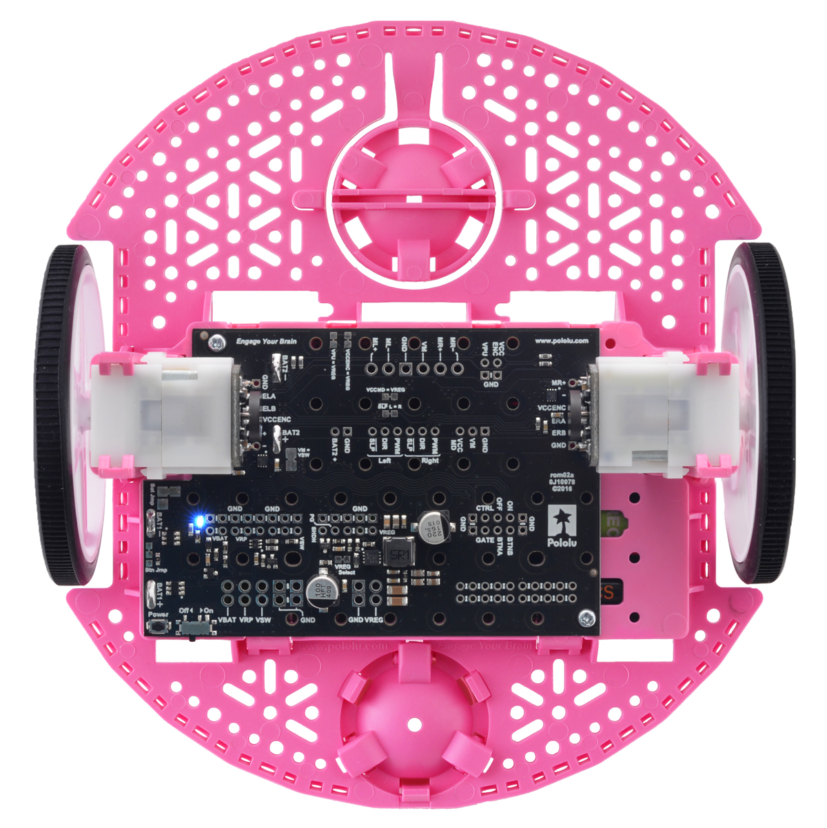
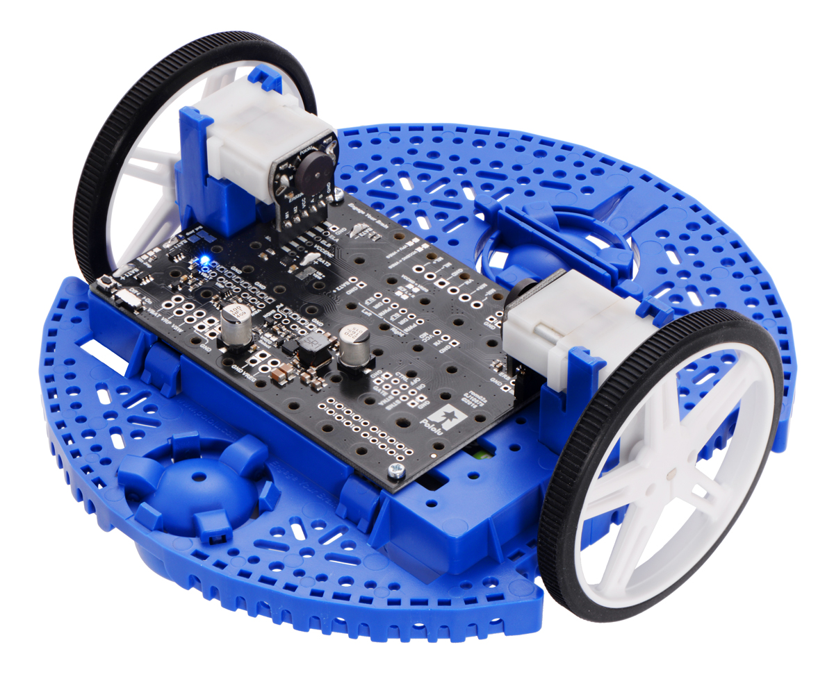
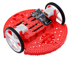
- Motor Driver and Power Distribution Board for Romi Chassis – This board is an alternative to the Power Distribution Board mentioned above. It offers the same features (reverse battery protection, multiple power switching options, and convenient access to various power busses) along with dual motor drivers and a powerful switching step-down voltage regulator that can deliver 2.5 A at 5 V or 3.3 V.
 | Motor Driver and Power Distribution Board for Romi Chassis. |
|---|
|
 | Motor Driver and Power Distribution Board for Romi Chassis. |
|---|
|
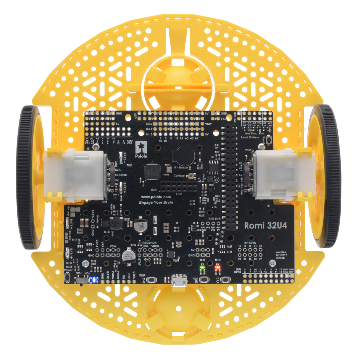
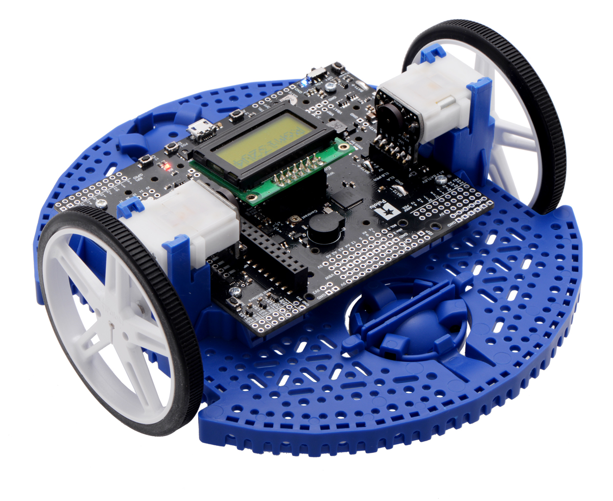
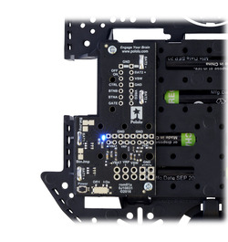
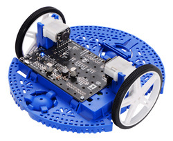
- Romi 32U4 Control Board – This board turns the Romi chassis into a programmable robot based on the Arduino-compatible ATmega32U4 MCU. Its features include integrated dual motor drivers, a versatile power circuit, and inertial sensors, as well as connections for quadrature encoders and an optional LCD. The board also has the ability to interface with an added Raspberry Pi, making the foundation for a complete Raspberry Pi-controlled Romi robot.
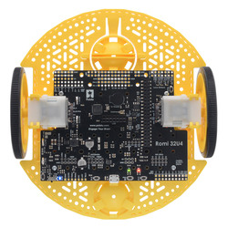 | Romi 32U4 Control Board on a Romi chassis, top view. |
|---|
|
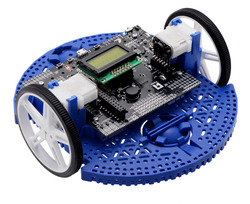 | Romi 32U4 Control Board with LCD on a Romi chassis. |
|---|
|
- Romi Encoder Pair Kit – Add quadrature encoders to the mini plastic gearmotors on your Romi chassis with this kit that uses a magnetic disc and Hall effect sensors to provide 12 counts per revolution of the motor shaft. These encoders can plug in directly to the Motor Driver and Power Distribution Board or the Romi 32U4 Control Board.
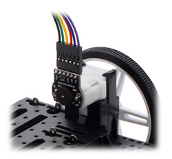 | The included low-profile headers are still long enough to work with our pre-crimped jumper wires. |
|---|
|
 | The Romi Encoder can plug directly into the Motor Driver and Power Distribution Board for Romi Chassis. |
|---|
|
- Romi Chassis components – Chassis components are available individually for use as spare parts or for those who want to put together their own Romi chassis with the color combinations of their choosing.
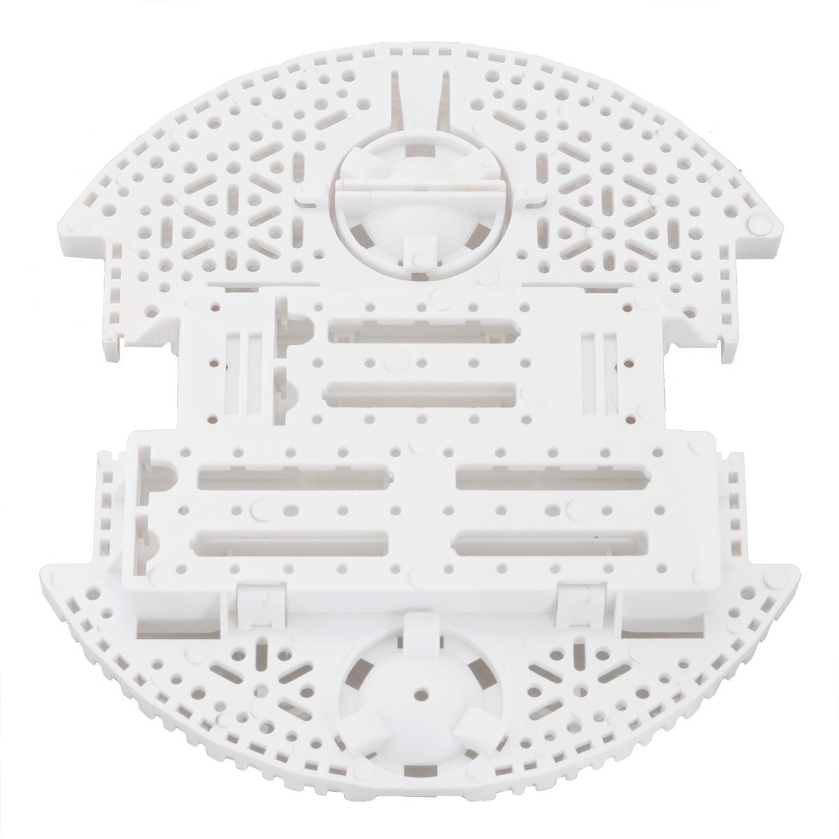
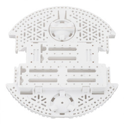 | Romi Chassis Base Plate – White. |
|---|
|
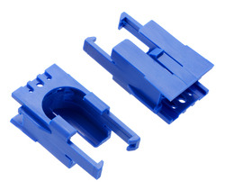 | Romi Chassis Motor Clip Pair – Blue. |
|---|
|
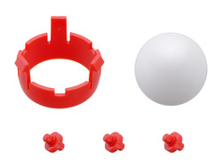 | Romi Chassis Ball Caster Kit – Red. |
|---|
|
 | Pololu Wheel 70×8mm Pair – Yellow. |
|---|
|
4. Assembling the Romi Chassis
Battery contacts and electronics
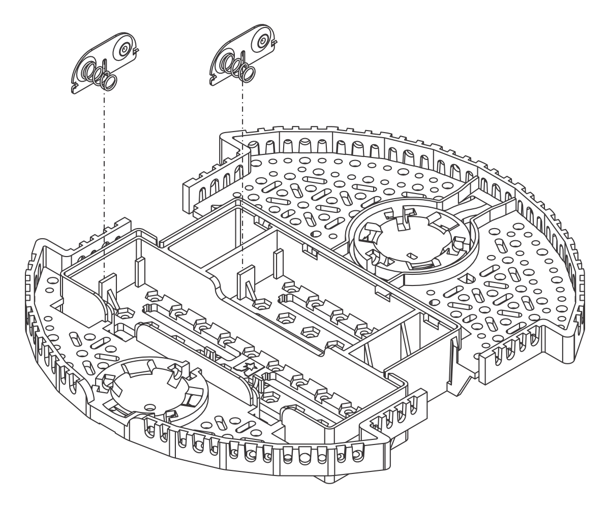
- With the chassis upside down, push the two double-sided battery contacts in the slots indicated in the picture below.
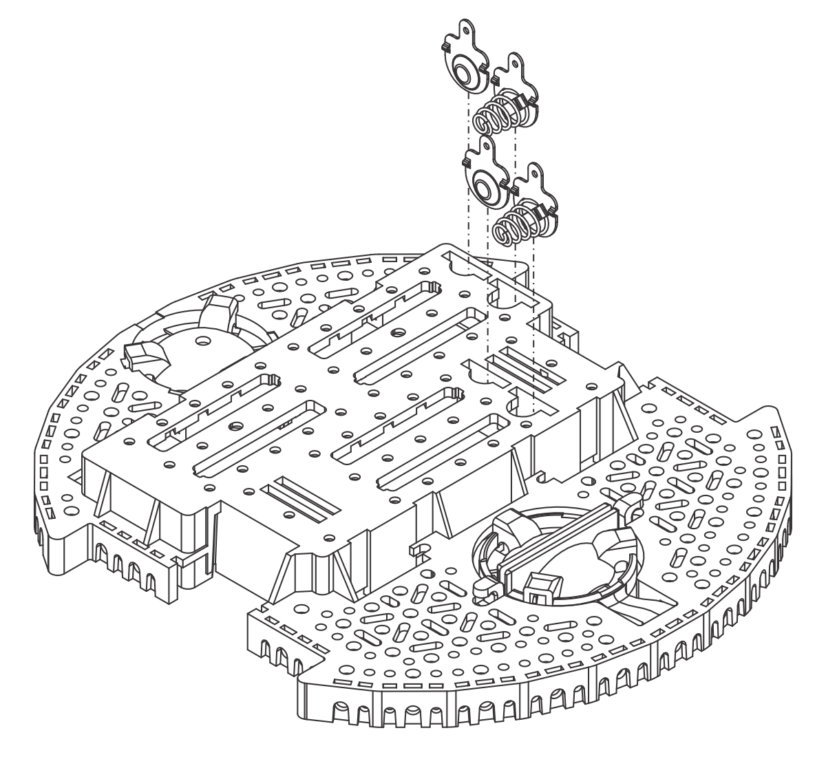
- Turn the chassis over and place the four individual battery contact terminals into the chassis from the top side of the battery box. They should rest loosely in their slots when the chassis is upright.
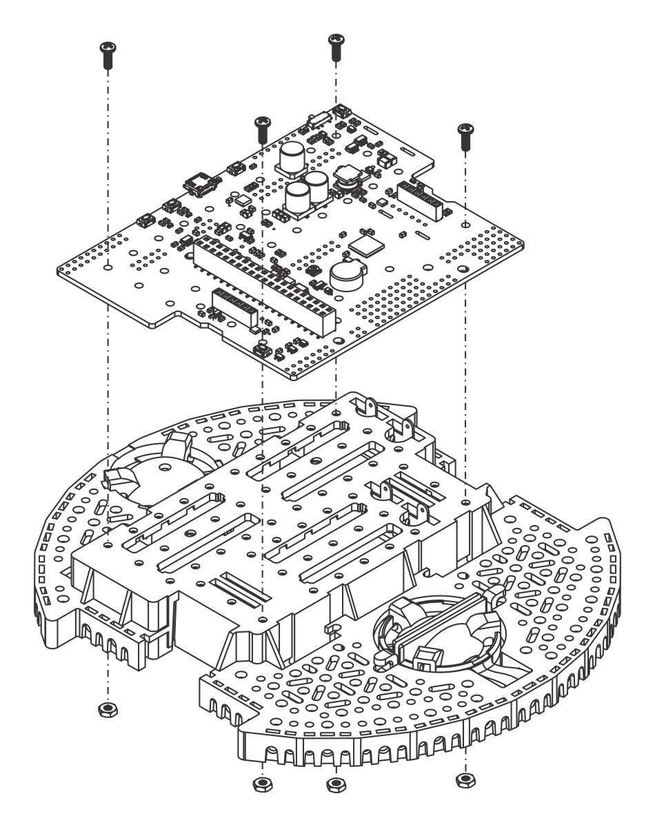
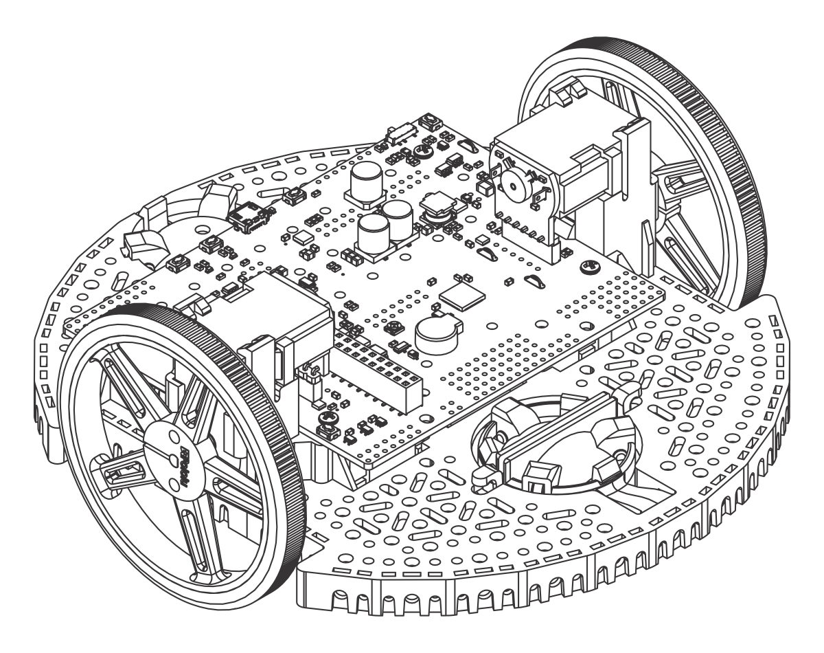
- Optional: If you have electronics that solder to the battery contacts, this is a convenient time to install them. The Romi 32U4 Control Board (not included) is shown below as an example.
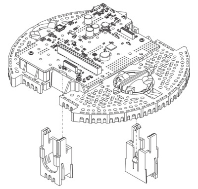
Motors
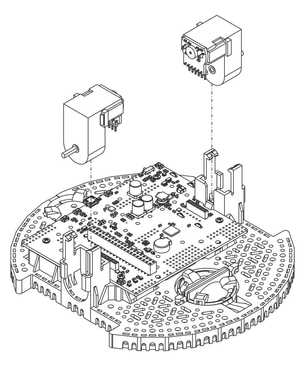
- Align the motor clips with the chassis as indicated and press them firmly into the chassis until the bottom of the clips are even with the bottom of the chassis (you may hear several clicks).
 |
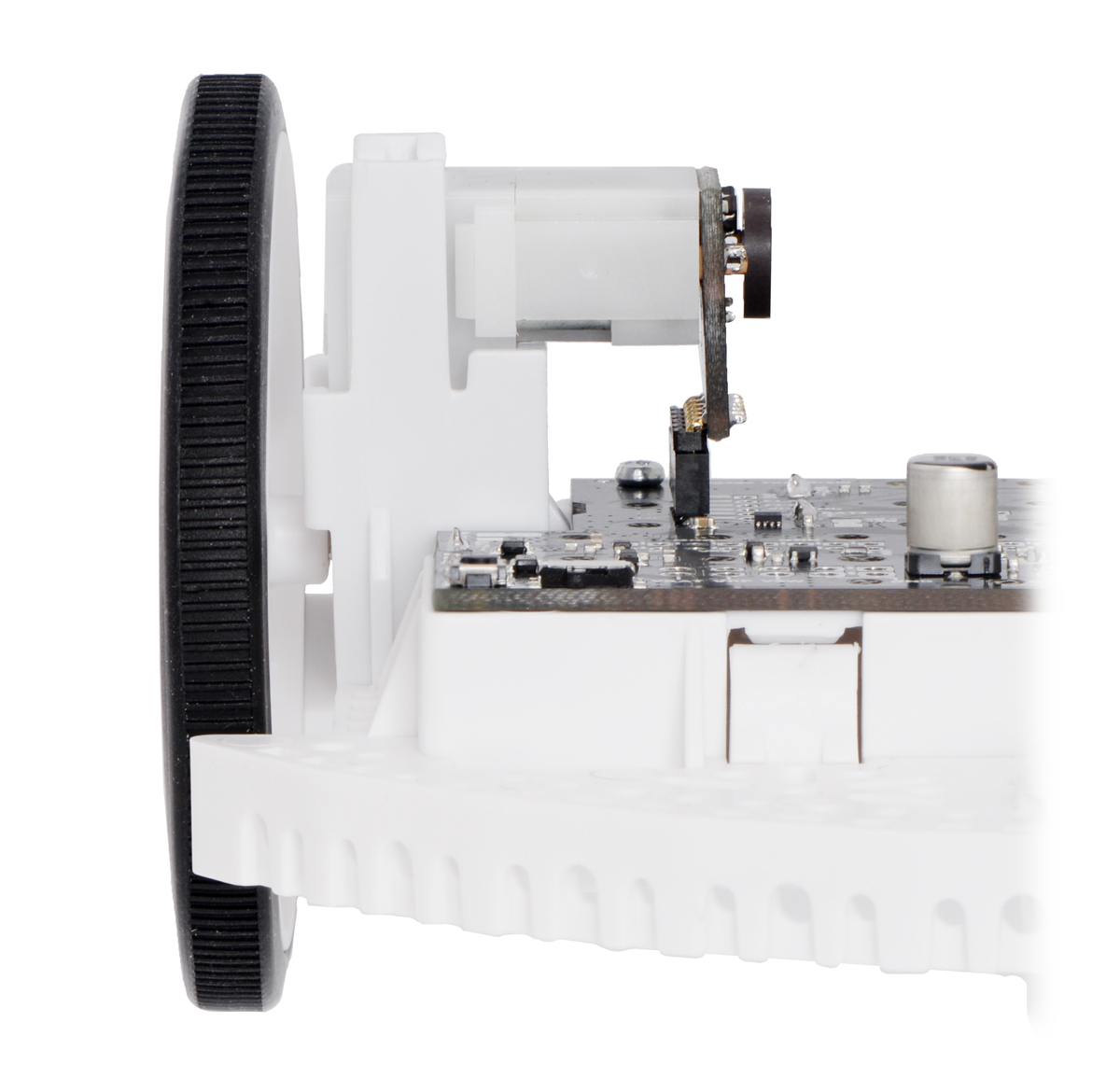
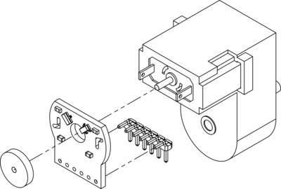
- Optional If you are using the Romi Encoder Pair Kit, you can now install the encoder boards. The encoder boards are designed to be soldered directly to the back of the motor, with the back shaft of the motor protruding through the hole in the middle of the circuit board. One way to achieve good alignment between the board and the motor is to tack down the board to one motor pin and to solder the other pin only when the board is flat and well aligned. Be careful to avoid prolonged heating of the motor pins, which could deform the motor case or brushes. If you are using one of our boards that are designed for these encoders to plug directly into, the encoder pins need to be installed pointing down toward the chassis as shown in the picture below. In order to help line up the header pins before soldering them, you can hold off soldering them to the encoder board until after the motors are installed in the next step.
 |
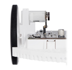
- Push the Mini Plastic Gearmotors into the motor clips until they snap into place. Note that the motor blocks the clip release, so if you need to remove a motor bracket later, you will first need to remove the motor. The Mini Plastic Gearmotors that come with the kit have extended motor shafts to enable quadrature encoders (not included) for position feedback.
Warning: If you are installing motors with encoders, do not press on the magnetic disc as you perform this step. Doing so could cause it to slide down the shaft and bind against the encoder electronics. Instead, hold the motor from the sides, and once installation is complete, check that there is ample space between the encoder disc and the encoder board (the motor shaft should be flush with the edge of the disc, not protruding through).
Wheels and ball casters
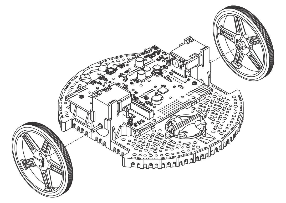
- Press the wheels onto the output shafts of the motors until the motor shaft is flush with the outer face of the wheel. One way to do this is to set the wheel on a flat surface and line the chassis up with it so that the flat part of the motor’s D-shaft lines up correctly with the wheel. Then, lower the chassis, pressing the motor shaft into the wheel until it contacts the surface.
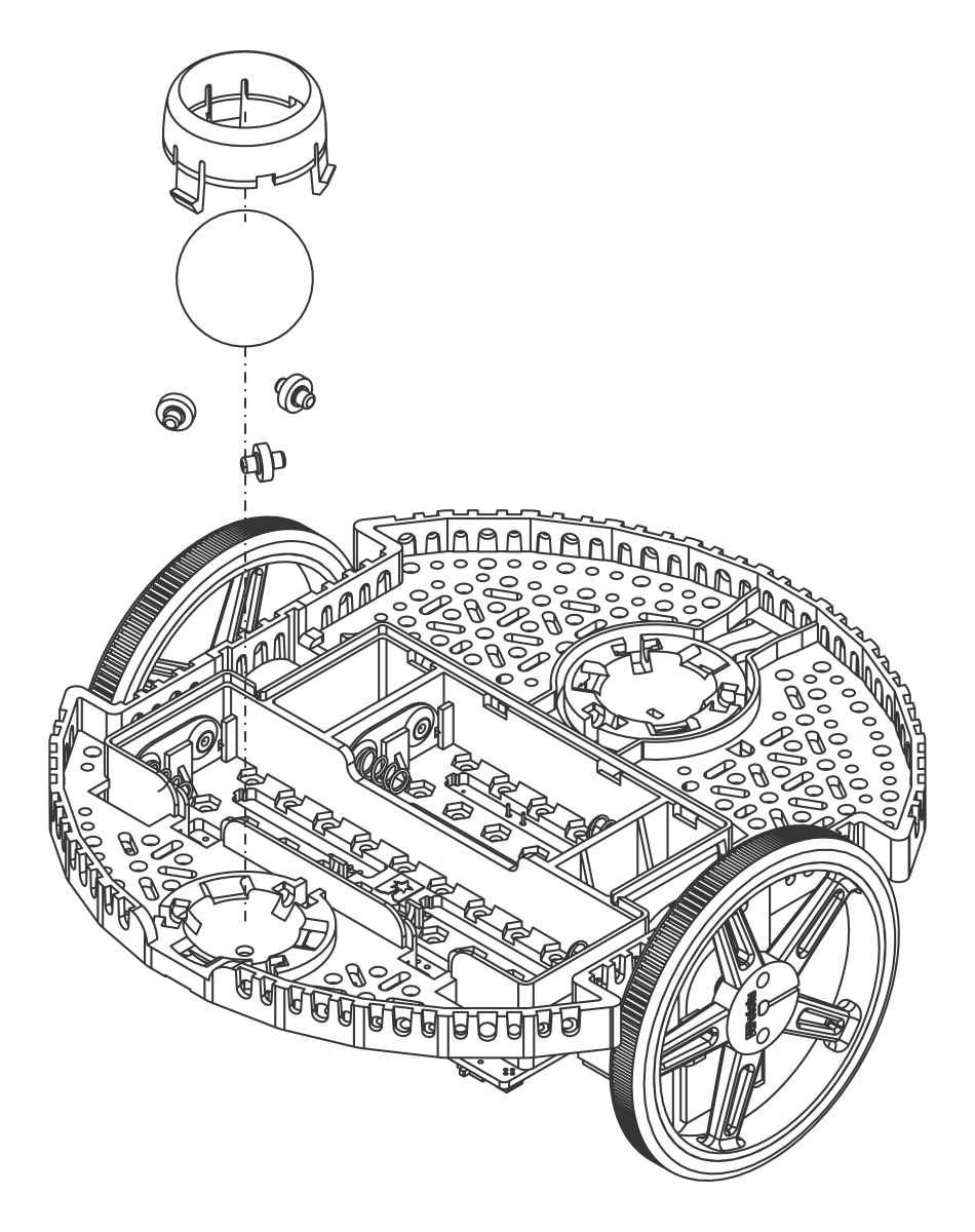
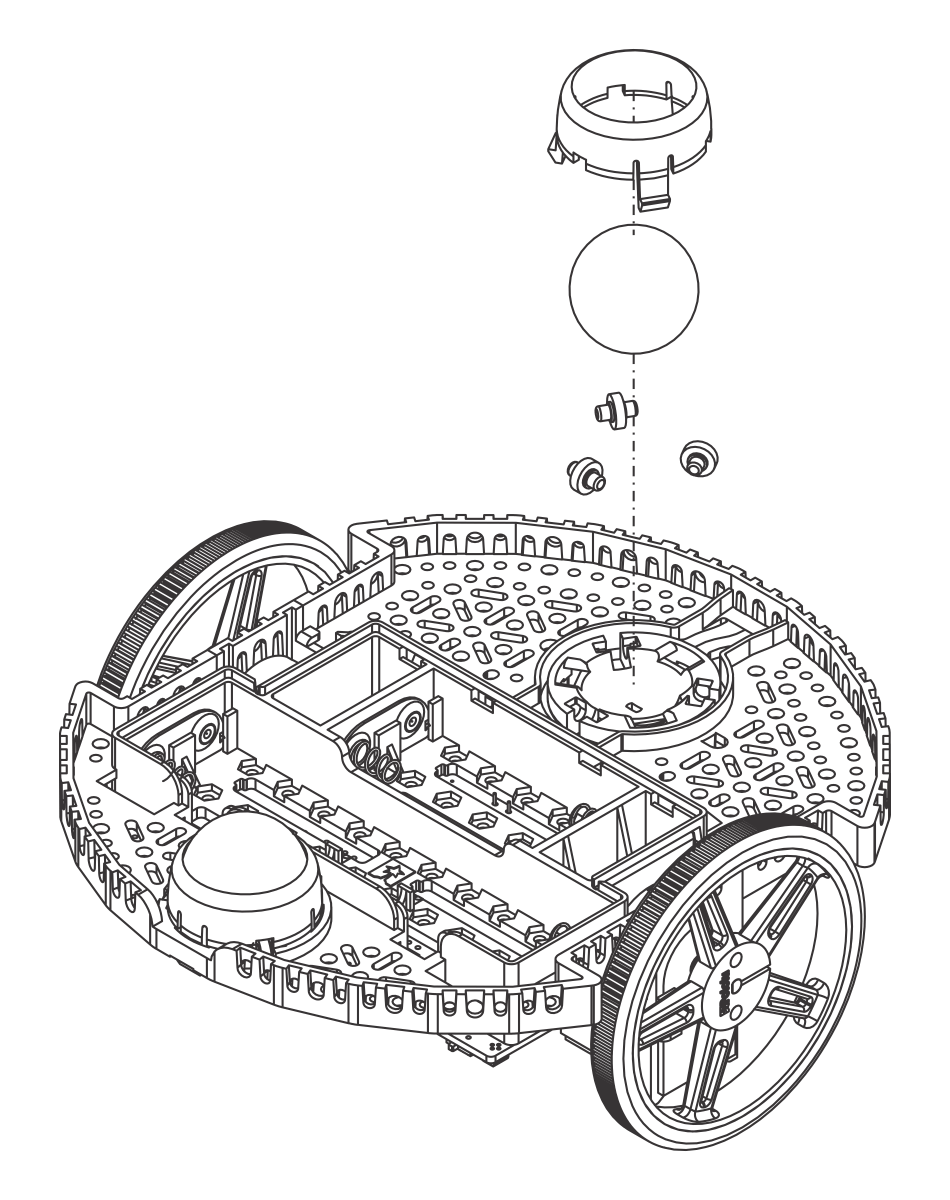
- Flip the chassis upside down and place the three rollers for the rear ball caster into the cutouts in the chassis.
- Place the 1″ plastic ball on top of the three rollers.
- Push the ball caster retention clip over the ball and into the chassis so the three legs snap into their respective holes.
- Optional: Repeat the above steps with the front ball caster socket to install the front ball caster. The Romi Chassis Kit only includes parts for the rear ball caster, but additional Romi Chassis Ball Caster Kits are available separately.
- Optional: The front ball caster is supported by a flexible arm that acts as a suspension system. If you want to make it stiffer, you can wrap a rubber band around the two hooks located on either side of the ball caster on the top side of the chassis.
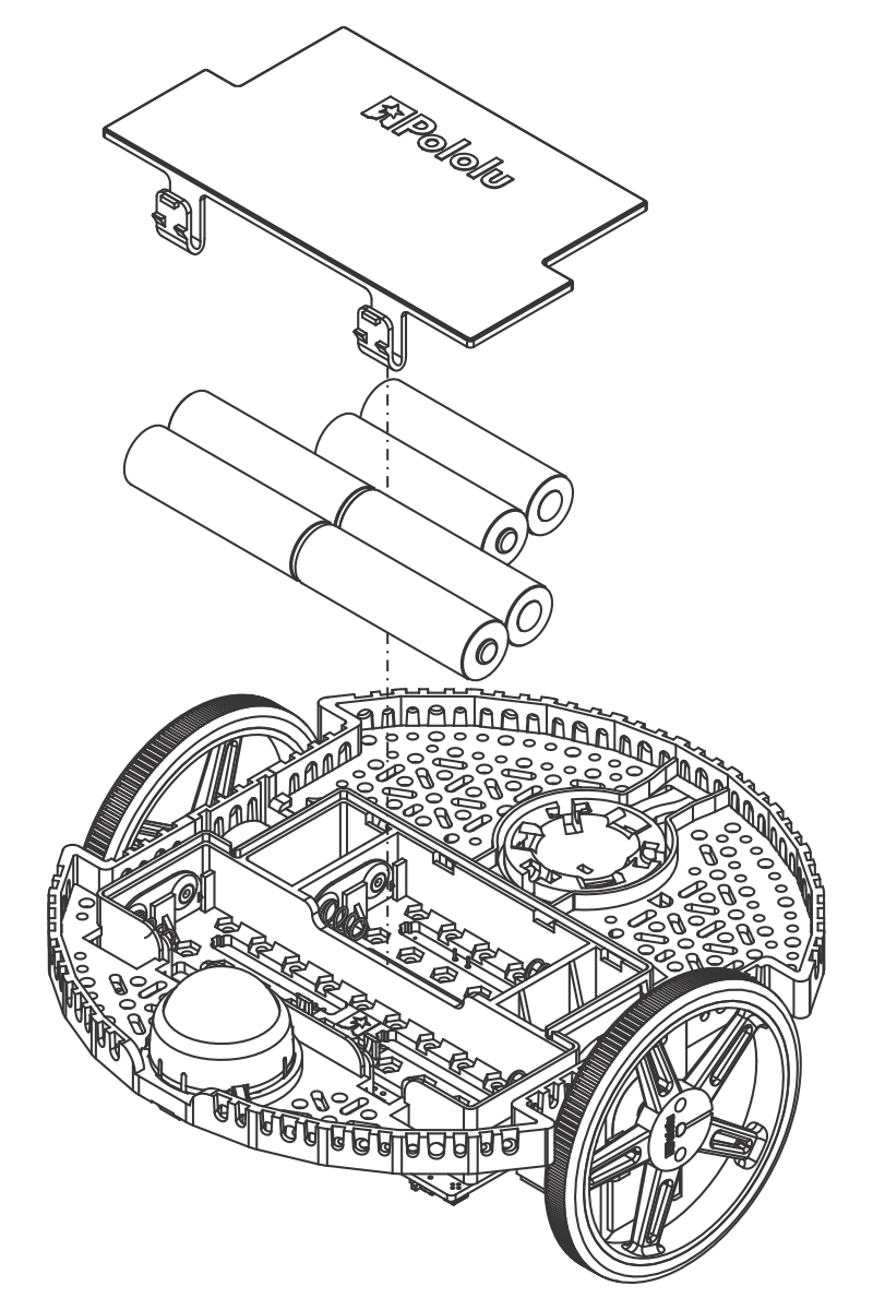
Batteries and battery cover
- The chassis works with four or six AA batteries (we recommend using rechargeable AA NiMH cells). The correct orientation for the batteries is indicated by the battery-shaped holes in the Romi chassis as well as the + and - indicators in the chassis itself. For more information about the various chassis power options, see Section 5.
The assembly of your Romi chassis is now complete!
5. Power options
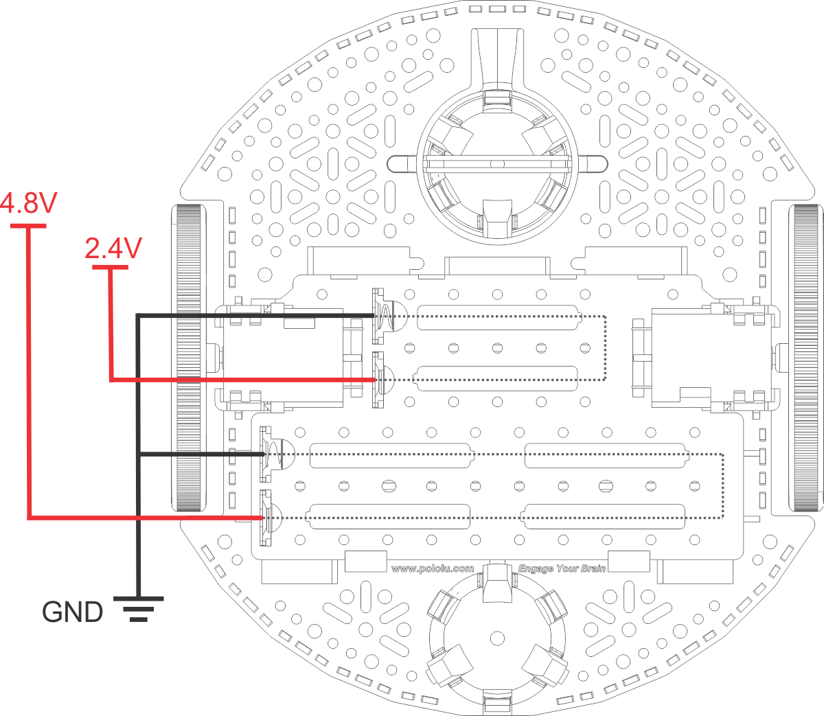
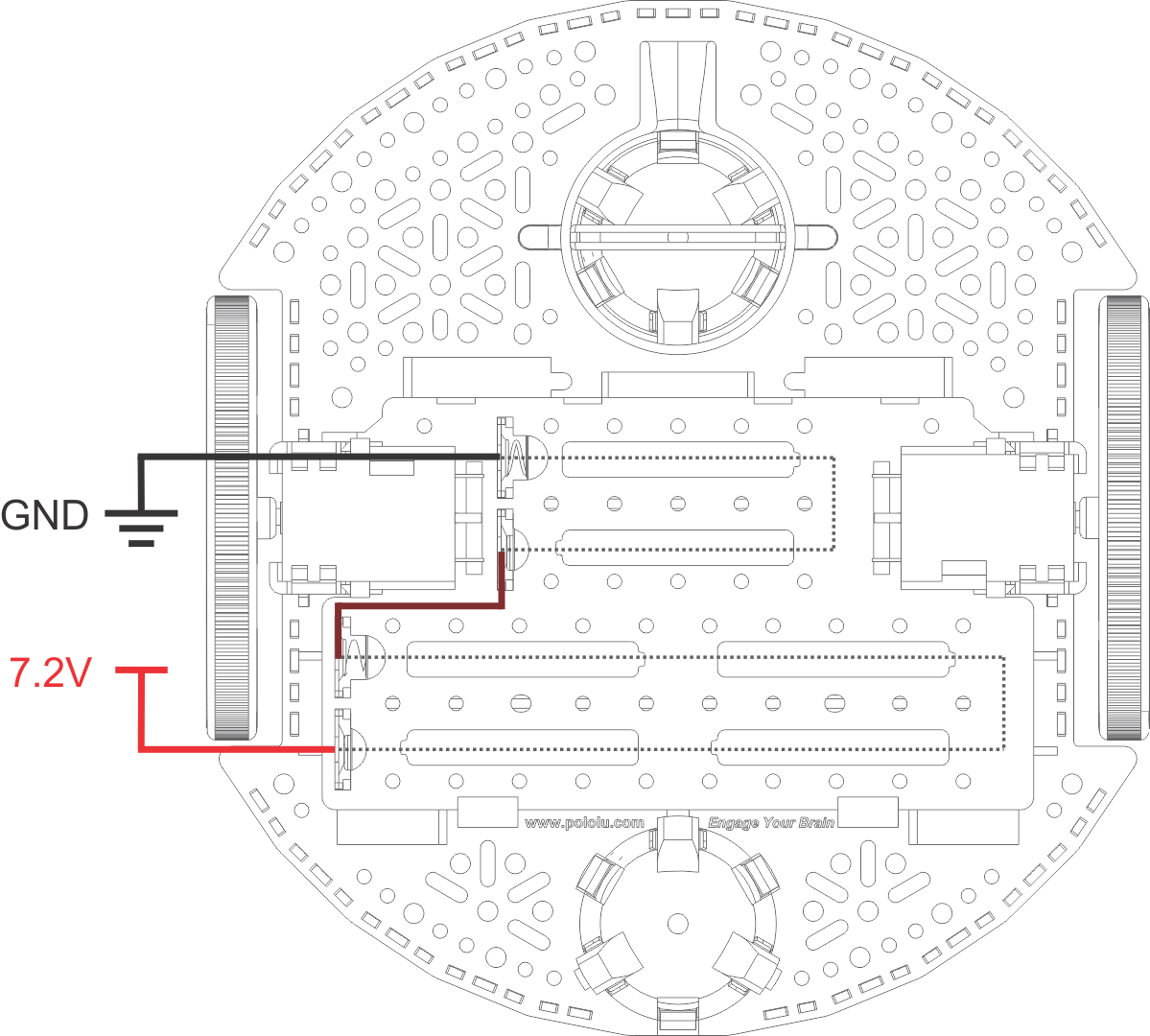
The Romi chassis has multiple options for configuring the batteries. The battery compartment is separated into two sections: a four-battery section and a two-battery section. Either section of the battery compartment can be used independently, shown in the diagram below with nominal NiMH voltages and a common ground:
Another option is to use all six batteries in series. To do this, simply solder a jumper wire from the negative terminal of the four-battery section to the positive terminal of the two-battery section as shown below:
If you use the Power Distribution Board for Romi Chassis, it defaults to getting power from all six batteries, but it can be reconfigured to be powered from four cells; see the board’s product page for more information.
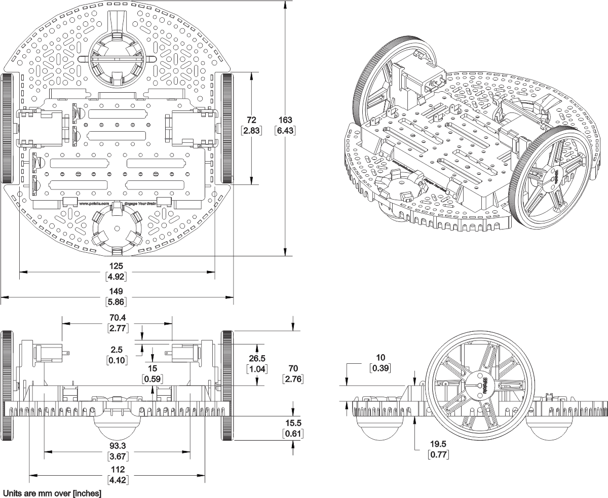
6. Dimensions and mounting holes
One of the features of the Romi chassis that makes it a great choice for a general purpose robotics platform is the multitude of mounting holes located all around the chassis. The mounting holes and slots are intended for various sizes of screws (not included) such as #2-56, #4-40, M2, and M3. Some of the key dimensions of the mounting holes are shown in the dimension diagram below, and additional dimensions can be found in the DXF file of the chassis (9MB dxf). An actual-size view of the top of the Romi chassis (115k pdf) is also available; just print it at 100% scale to make a template showing where all of the general-purpose mounting holes and slots are.
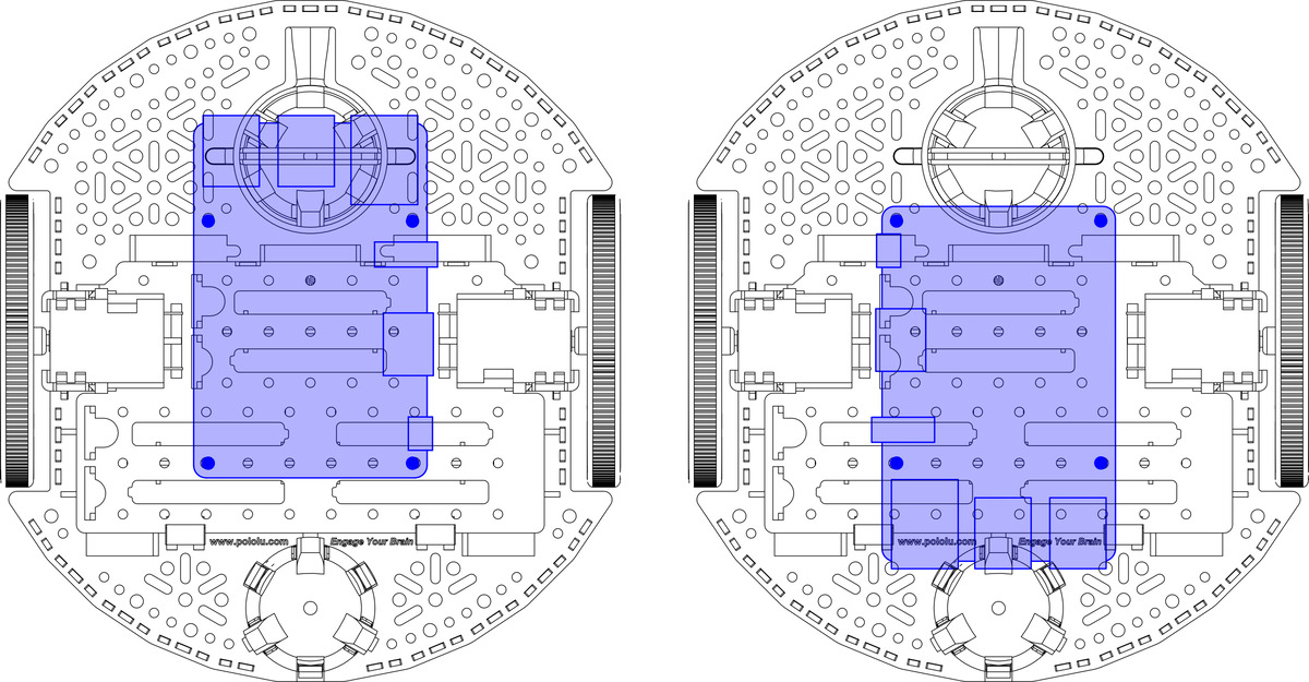
Mounting holes for the common Arduino form factor
The diagram below shows the mounting holes intended for electronics that use a common Arduino form factor, including the Arduino Uno R3 and A-Star 32U4 Prime.
Please note that the two mounting holes indicated above are on two surfaces of differing heights. The top of the battery box sits 10 mm higher than the round base. One way to compensate for this is to use spacers. In particular, a 10 mm spacer can match the battery box height, then 4 mm or 6 mm spacers can raise the electronics enough to make room for components that protrude below the bottom surface of the PCB.
If you are using an Arduino for controlling the Romi, you might consider our DRV8835 Dual Motor Driver Shield for Arduino.
Mounting holes for the Raspberry Pi
The Romi chassis also has mounting holes intended for use with a Raspberry Pi. These holes support the form factor and mounting hole locations used on the Raspberry Pi A+, Raspberry Pi B+, Raspberry Pi 2 Model B, and Raspberry Pi 3 Model B. Additionally, our A-Star 32U4 Robot Controller with Raspberry Pi Bridge (which is an Arduino-compatible programmable module designed to be an auxiliary controller atop a Raspberry Pi or a stand-alone control solution on its own) has mounting hole locations as these Raspberry Pi boards.
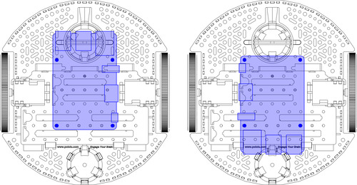 |
Similarly to the Romi mounting holes used for the Arduino, the mounting holes used for the Raspberry Pi are also on surfaces of two different heights. As mentioned above, a few spacers can be used to raise the board to an appropriate height. However, when using a Raspberry Pi, it can be beneficial to raise the board even more, enough to allow access to the HDMI port by simply removing a motor from a motor clip. To do this, the Raspberry Pi should be raised about 15 mm above the top of the battery box. This can be accomplished with two 25 mm spacers for the front mounting holes and two 15 mm spacers for the rear ones. Please note that using such long spacers will require some uncommonly long #2-56 or M2.5 screws.
An alternative solution is to use some of our 11 mm aluminum standoffs for the Raspberry Pi, which is especially helpful when using a Raspberry Pi HAT or expansion board since the same standoff can be used to mount that board to the Raspberry Pi. Stacking two of the 11 mm standoffs for the front mounting holes can help compensate for the longer distance; however, to reach the height previously mentioned to access the HMDI port through the motor clip, you will need to use some nuts or washers for the extra few millimeters as shown below:
If you are using a Raspberry Pi for controlling the Romi, you might consider our DRV8835 Dual Motor Driver Kit for Raspberry Pi, the A-Star 32U4 Robot Controller with Raspberry Pi Bridge, or one of our other Raspberry Pi Expansion Boards.
7. Next steps
You are now ready to add some electronics to turn your Romi chassis into a functional robot!
Have you built a robot with the Romi that you would like to share? Please join us on our robotics forum to ask questions, give feedback, or share your projects. We would love to hear about your experiences with the Romi!