Robot Kits » Romi Chassis and Accessories »
Motor Driver and Power Distribution Board for Romi Chassis

Use this motor driver and power distribution board to get your Romi chassis running quickly. It offers all of the same features as the smaller Power Distribution board for Romi Chassis — battery contact slots, reverse voltage protection, several power switching options, and easy access to the various power busses — and adds a two-channel motor driver and powerful switching step-down regulator that can supply a continuous 2.5 A at 5 V or 3.3 V. Just add a microcontroller and sensors to complete your Romi robot.
 Compare all products in Romi Chassis and Accessories or Classic TI-RSLK Parts and Accessories.
| Description | Specs (11) | Pictures (13) | Resources (6) | FAQs (0) | On the blog (2) | Distributors (37) |
|---|
 |
Overview
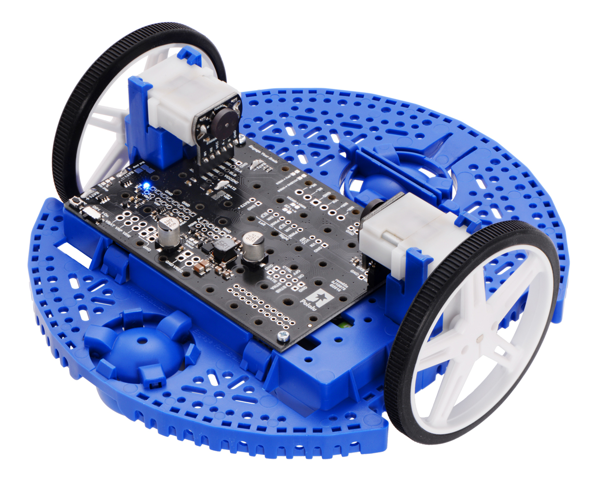
This motor driver and power distribution board is designed specifically for the Romi chassis as a convenient way to drive the chassis’s motors and power the rest of the electronics that make up your robot. It features two DRV8838 motor drivers, one for each of the chassis’s motors, and a powerful switching step-down regulator that can supply a continuous 2.5 A at 5 V or 3.3 V. The board has slots for soldering in the Romi chassis battery contact tabs, and it incorporates the power switching and distribution functionality from the Power Distribution Board for Romi Chassis, so it offers all of the same features: reverse voltage protection, several power switching options based on the patented latching circuit from the Pololu pushbutton power switch, and easy access to the various power buses.
The board has a small pushbutton already installed for controlling power (one push turns power on and another push turns it off) and offers convenient points for connecting external pushbutton or tactile switches in parallel. It also offers several alternate pushbutton connection options that result in push-on-only or push-off-only operation, and additional inputs enable further power control options like allowing your robot to turn off its own power. Alternatively, the board can be reconfigured to disable the pushbutton circuit and give control to the small installed slide switch.
The board’s control pins and power buses are accessible through a set of 0.1″-spaced pins that are compatible with standard 0.1″ male and 0.1″ female headers, and the power buses are also accessible through a larger set of holes that are compatible with 3.5mm-pitch terminal blocks (you can combine a 2-pin block and a 3-pin block into a single 5-pin block that spans the three power holes and two ground holes).
Two 1/4″ #2-56 screws and two #2-56 nuts are included for mounting the board to the Romi chassis, and two low-profile female headers are included for connecting the motors to the board.
Using the board
Installation
|
|
Before installing the motor driver and power distribution board on a Romi chassis, you should solder any headers, terminal blocks, wires, or other connectors you plan to use on the board. You have a few options for connecting the Romi chassis’s motors to the board:
- If you plan on using the Romi Encoder Pair Kit with your motors, we recommend you solder these included female headers into the outer sets of holes (closest to the edges of the board) directly below where the motors will be. With the Romi encoders mounted on your motors and their included male header pins installed facing down, they will plug directly into these female headers when you push the motors into the motor clips.
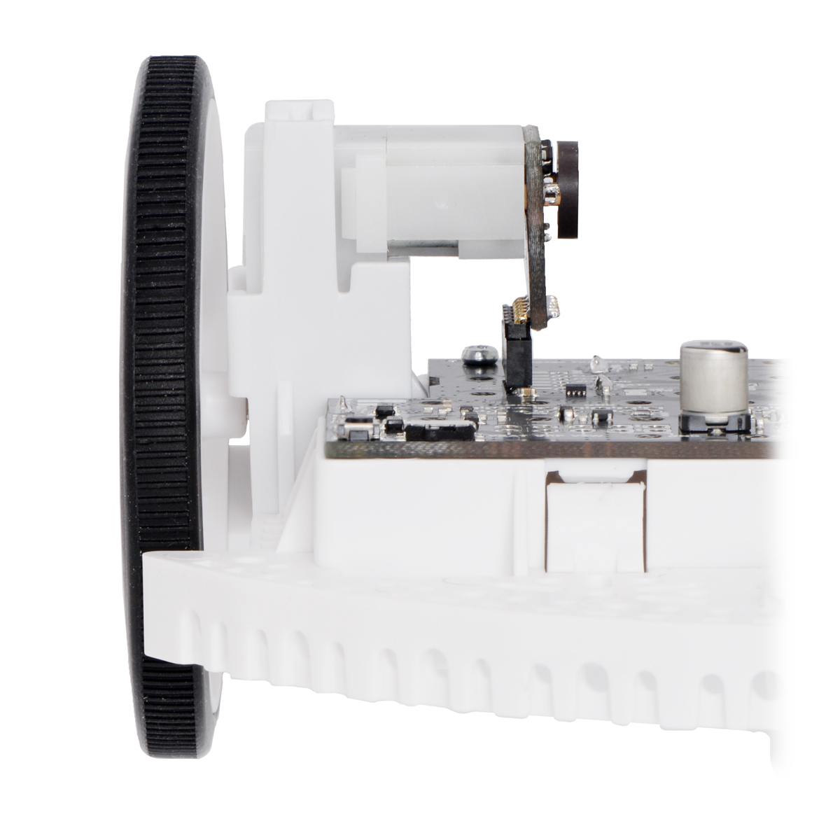 |
The Romi Encoder can plug directly into the Motor Driver and Power Distribution Board for Romi Chassis. |
|---|
- Alternatively, if you do not intend to use Romi encoders, we recommend soldering wires to your motor leads and installing 3.5mm-pitch terminal blocks to the motor driver output holes along the front edge of the board. These terminal blocks will let you make temporary connections between your motors and the motor driver board. We suggest connecting the forward lead of each motor to the + (positive) motor output so that the motor directions will match the behavior described below.
Please read the rest of this page carefully to determine what additional connectors you might want and where they should be installed.
It is possible to remove the board from the chassis later to solder additional connections, and some of the through holes can be soldered through the slots in the chassis while the board is mounted, but soldering beforehand is easier and avoids the risk of inadvertently melting the chassis with your soldering iron.
The four battery terminals should be soldered to the board after it is mounted on the chassis, as described in the chassis assembly instructions. You will be able to remove the board and battery contacts from the chassis as a single piece after soldering.
Once your you have soldered your through-hole connections to the motor driver and power distribution board, please follow the instructions given in the Pololu Romi Chassis User’s Guide to finish assembling the chassis, mounting the control board, and soldering in the battery contacts. (The diagrams in those instructions show assembly with the larger Romi 32U4 Control Board, but the same steps apply for the smaller motor driver and power distribution board.)
Motor drivers
The motor driver and power distribution board has two Texas Instruments DRV8838 motor drivers that can power the Romi chassis’s motors. We recommend careful reading of the DRV8838 datasheet for information about the drivers.
By default, the drivers’ motor voltage (VM) is supplied by the board’s switched battery voltage, VSW, and their logic voltage (VCCMD) is supplied by the on-board regulator output, VREG (5 V by default). If you want to customize these voltages, you can cut the jumpers labeled VM = VSW and VCCMD = VREG and connect appropriate supplies to the VM and VCCMD pins.
The DRV8838 offers a simple two-pin PHASE/ENABLE control interface, which this board makes available for each motor as DIR and PWM, respectively. The DIR pin determines the motor direction (low drives the motor forward, high drives it in reverse) and the PWM pin can be supplied with a PWM signal to control the motor speed. The DIR and PWM control inputs are pulled low through weak internal pull-down resistors (approximately 100 kΩ). When the PWM pin is low, the motor outputs are both shorted to ground, which results in dynamic braking of a connected motor.
The two drivers’ SLEEP pins (labeled SLP) are connected together by default and can be driven low to put the drivers into a low-power sleep mode and turn off the motor outputs, which is useful if you want to let the motors coast. The SLEEP pins are pulled high through 10 kΩ pull-up resistors on the board so that the drivers are awake by default. In most applications, these pins can be left disconnected; if you want independent control of SLEEP on each side, you can cut the jumper labeled SLP L = R. The two SLEEP pins should not be driven separately without cutting this jumper.
The following simplified truth table shows how each driver operates:
| DIR | PWM | SLEEP | Motor + | Motor − | operating mode |
|---|---|---|---|---|---|
| 0 | PWM | 1 | PWM | L | forward/brake at speed PWM % |
| 1 | PWM | 1 | L | PWM | reverse/brake at speed PWM % |
| X | 0 | 1 | L | L | brake low (outputs shorted to ground) |
| X | X | 0 | Z | Z | coast (outputs floating/disconnected) |
Encoder connections
The motor driver and power distribution board is designed to allow the Romi Encoder Pair Kit to plug directly into the encoder headers. The encoders can be used to track the rotational speed and direction of the robot’s drive wheels. They provide a resolution of 12 counts per revolution of the motor shaft when counting both edges of both channels, which corresponds to approximately 1440 counts per revolution of the Romi’s wheels. For more information about the specifications of the Romi encoders, please see the Romi Encoder Pair Kit product page.
For typical use, one set of through holes on each side of the motor power and distribution board will be populated with the female header for the encoder board; we recommend using the outer set on each side for this purpose. The remaining set of through holes can be used to make connections to the encoder signals.
For both encoders, channel B leads channel A when the motor is rotating in the forward direction; that is, B rises before A rises and B falls before A falls. Note that this description designates the A and B signals as labeled on the motor driver and power distribution board itself, which puts A in front on both sides.
By default, both the logic voltage for the encoders (VCCENC) and the pull-up voltage for the open-drain encoder outputs (VPU) are supplied by the on-board regulator output, VREG (5 V by default). If you want to customize these voltages, you can cut the jumpers labeled VCCENC = VREG and VPU = VREG and connect appropriate supplies to the VCCENC and VPU pins.
Power switch circuit
By default, the on-board pushbutton can be used to toggle power: one push turns on power and another turns it off. Alternatively, a separate pushbutton can be connected to the BTNA and BTNB pins and used instead. Multiple pushbuttons can be wired in parallel for multiple control points, and each of the parallel pushbuttons, including the one on the board itself, will be able to turn the switch on or off. The latching circuit performs some button debouncing, but pushbuttons with excessive bouncing (several ms) might not function well with it.
For proper pushbutton operation, the board’s slide switch should be left in its Off position. (Sliding the switch to the On position will cause the board power to latch on, and the switch must be returned to the Off position before the board can be turned off with the pushbutton.)
Alternatively, to disable the pushbutton, you can cut the button jumper labeled Btn Jmp; this transfers control of the board’s power to the on-board slide switch instead. A separate slide or toggle switch can be connected to the GATE pin and used instead.
More advanced control options are available through the button connection pins and four control inputs:
| PIN | Description |
|---|---|
| BTNA | Connect through momentary switch to pin “BTNB” for standard push-on/push-off operation. Connect through momentary switch to ground for on-only operation. |
| BTNB | Connect through momentary switch to pin “BTNA” for standard push-on/push-off operation. |
| ON | A high pulse (> 1 V) on this pin turns on the switch circuit. This pin only functions when pushbutton operation is enabled (i.e. the button jumper has not been cut). |
| OFF | A high pulse (> 1 V) on this pin turns off the switch circuit (e.g. allowing a powered device to shut off its own power). This pin only functions when pushbutton operation is enabled. |
| CTRL | With pushbutton operation enabled, this pin directly determines the state of the switch circuit. A high pulse (> 1 V) on this pin turns on the switch; a low pulse (e.g. driving the pin low with a microcontroller output line or pushing a button connected from this pin to ground) turns the switch off. Leave this pin disconnected or floating when not trying to set the switch state. Note that this pin should not be driven high at the same time the “OFF” pin is driven high. |
| GATE | With pushbutton operation disabled (button jumper cut), this pin controls the state of the switch circuit: driving it low turns the switch on, while letting it float turns the switch off. Connect through slide or toggle switch to ground for on/off operation. Leave this pin disconnected or floating for proper pushbutton operation. We recommend only ever driving this pin low or leaving it floating; this pin should never be driven high while the slide switch is in the “Off” position. |
Power distribution
The diagram below shows the layout of the power distribution buses and access points on the board.
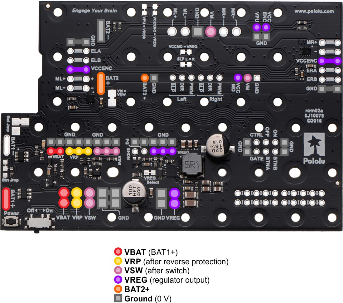 |
- VBAT is connected to the battery contact labeled BAT1+ and provides a direct connection to the battery supply. By default, VBAT is the high side of all six of the chassis’s AA battery cells in series, although this can be reconfigured with the battery jumper (see below).
- VRP provides access to the battery voltage after reverse-voltage protection.
- VSW is the battery voltage after reverse protection and the power switch circuit. By default, it provides power to the motors (VM) through the on-board motor drivers.
- VREG is the output of the on-board step-down voltage regulator (see the “Voltage regulator” section below). By default, it is 5 V and provides logic power to the motor drivers (VCCMD) and encoder connectors (VCCENC and VPU).
- BAT2+ provides access to the high side of two AA cells in series. This can be useful if you reconfigure the board to provide two separate battery supplies as described below.
Voltage regulator
An MP4423H switching buck converter regulates the switched battery voltage (VSW) to provide a regulated output, VREG. The regulated output is 5 V by default, but it can be changed to 3.3 V by cutting the jumper labeled VREG Select. Under typical conditions, up to 2 A of current is available from the VREG output. (We also make a standalone regulator based on this integrated circuit.)
Battery supply configuration
The motor driver and power distribution board’s default configuration provides battery power, VBAT, from all six of the chassis’s AA cells in series (nominally about 7.2 V with rechargeable batteries or 9 V with alkaline batteries). However, the board’s battery jumper, labeled Bat Jmp, allows you to reconfigure the battery connections to provide two independent supplies: BAT1, with 4 cells in series (nominally 4.8 V rechargeable or 6 V alkaline), and BAT2, with 2 cells in series (nominally 2.4 V rechargeable or 3 V alkaline). Cutting the connection between the BAT1− and BAT2+ pads separates the two sets of batteries, and using solder to bridge the BAT1− and GND pads establishes a common ground between the two new supplies.
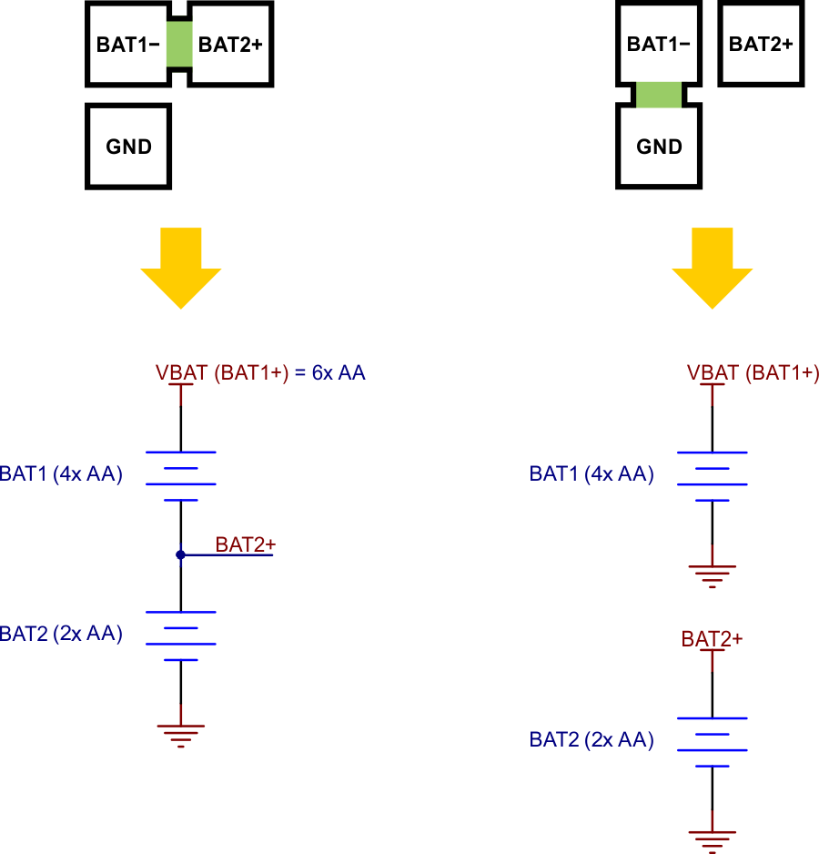 |
Warning: Do not bridge the BAT1− and GND pads without first disconnecting BAT1− from BAT2+. Failing to do so could create a short circuit across the BAT2 batteries.
Note that the onboard regulator might not be able to supply 5 V as reliably if VBAT is reconfigured to come from a 4-cell supply, especially if you are using rechargeable batteries.
Schematic
A simplified schematic diagram of this board is available for download: Schematic diagram of the Motor Driver and Power Distribution Board for Romi Chassis (272k pdf)
Other Romi boards
In addition to the motor driver and power distribution board, we have a few other boards designed to mount onto a Romi chassis:
- The Romi 32U4 Control Board turns the Romi chassis into an integrated robot platform. In addition to the same motor drivers and power circuit (including 5 V regulator) found on this board, the Romi 32U4 board includes an on-board ATmega32U4 microcontroller, a number of other peripherals and sensors, and interfaces for an optional LCD or Raspberry Pi.
- The Power Distribution Board for Romi Chassis is a more basic board that only includes reverse voltage protection and a pushbutton power switch circuit; it is intended to be a convenient way to access the chassis’s battery power and pass it on to the rest of your electronics.
Related products


Home | Forum | Blog | Support | Ordering Information | Lists | Distributors | BIG Order Form | About | Contact
© 2001–2026 Pololu Corporation
