Battery contacts and electronics
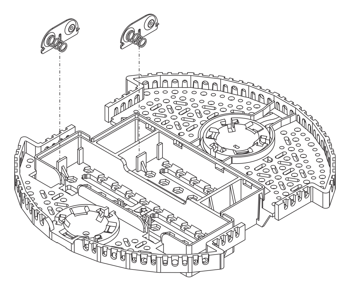
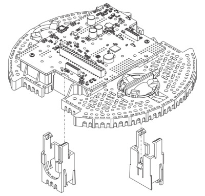
- With the chassis upside down, push the two double-sided battery contacts in the slots indicated in the picture below.
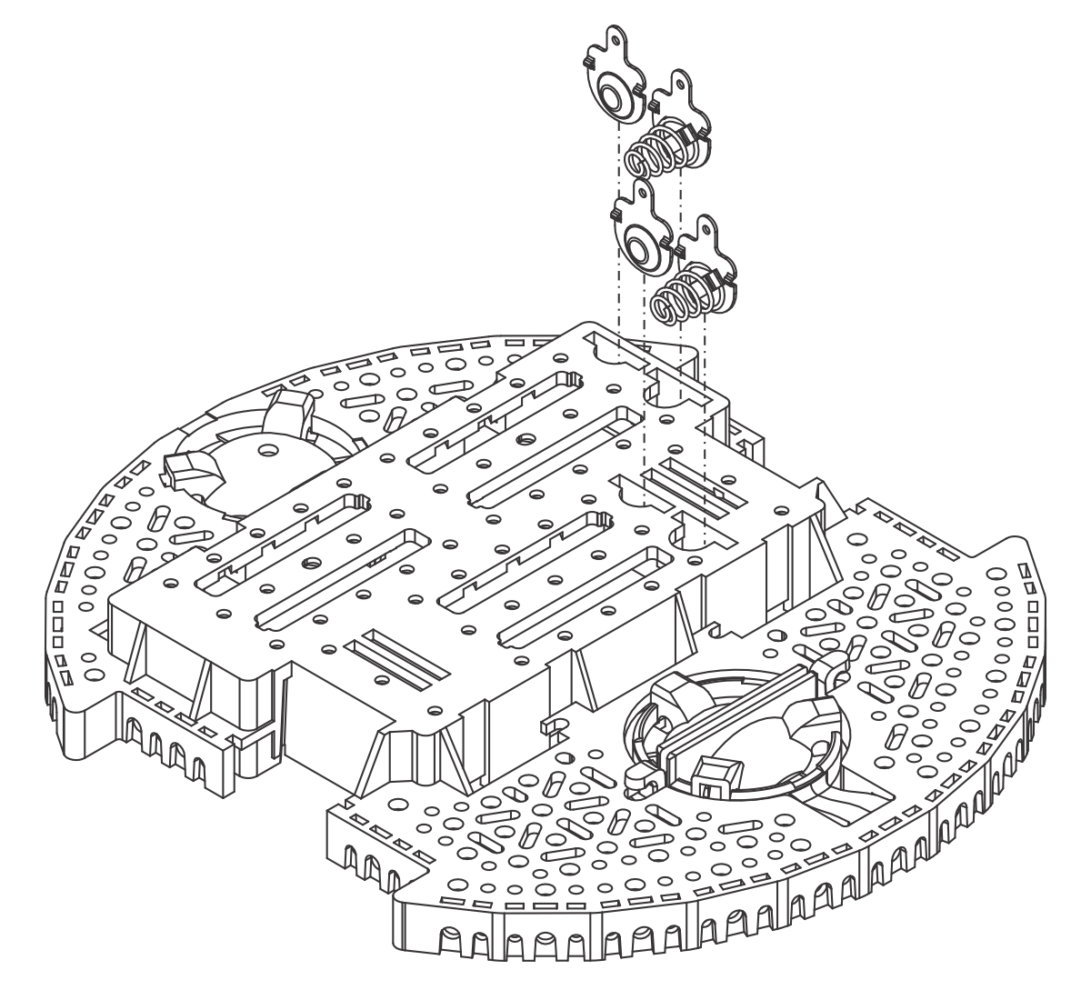
- Turn the chassis over and place the four individual battery contact terminals into the chassis from the top side of the battery box. They should rest loosely in their slots when the chassis is upright.
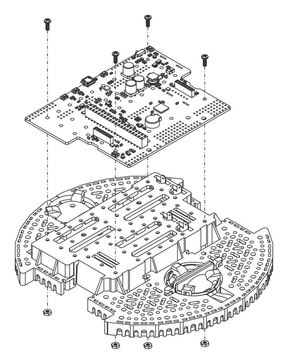
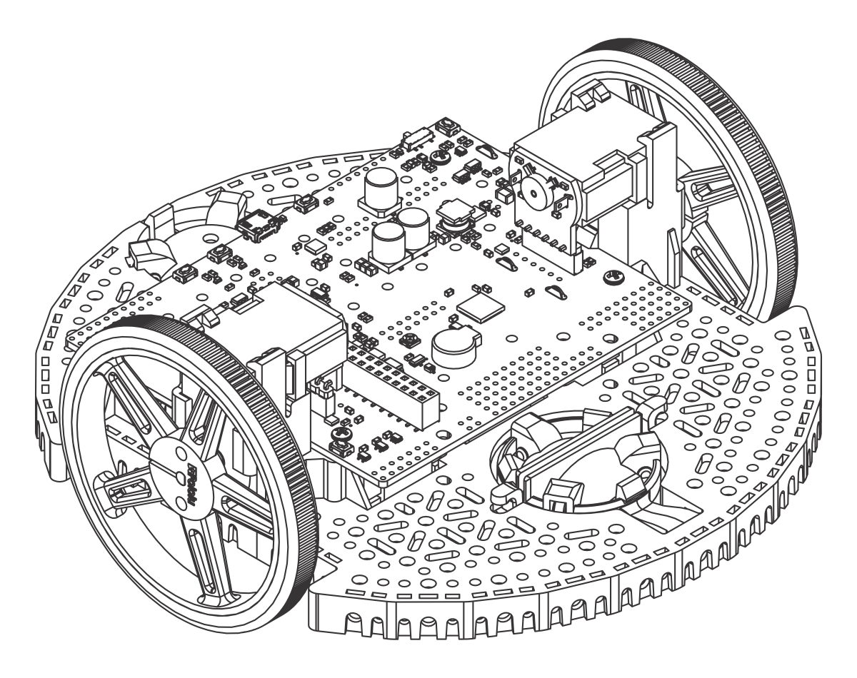
- Optional: If you have electronics that solder to the battery contacts, this is a convenient time to install them. The Romi 32U4 Control Board (not included) is shown below as an example.
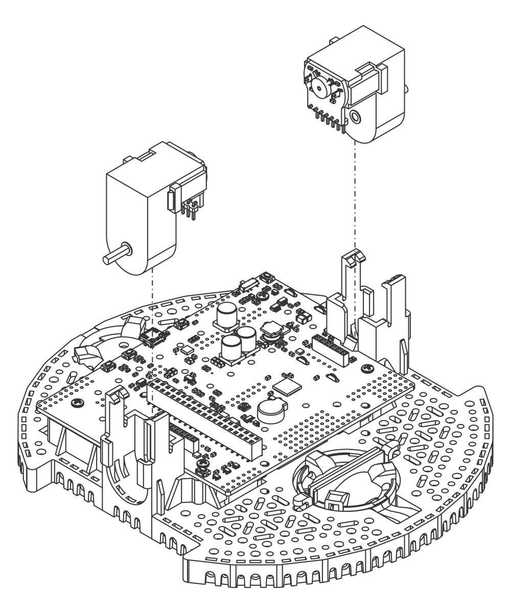
Motors
- Align the motor clips with the chassis as indicated and press them firmly into the chassis until the bottom of the clips are even with the bottom of the chassis (you may hear several clicks).
 |
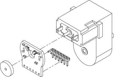
- Optional If you are using the Romi Encoder Pair Kit, you can now install the encoder boards. The encoder boards are designed to be soldered directly to the back of the motor, with the back shaft of the motor protruding through the hole in the middle of the circuit board. One way to achieve good alignment between the board and the motor is to tack down the board to one motor pin and to solder the other pin only when the board is flat and well aligned. Be careful to avoid prolonged heating of the motor pins, which could deform the motor case or brushes. If you are using one of our boards that are designed for these encoders to plug directly into, the encoder pins need to be installed pointing down toward the chassis as shown in the picture below. In order to help line up the header pins before soldering them, you can hold off soldering them to the encoder board until after the motors are installed in the next step.
 |
- Push the Mini Plastic Gearmotors into the motor clips until they snap into place. Note that the motor blocks the clip release, so if you need to remove a motor bracket later, you will first need to remove the motor. The Mini Plastic Gearmotors that come with the kit have extended motor shafts to enable quadrature encoders (not included) for position feedback.
Warning: If you are installing motors with encoders, do not press on the magnetic disc as you perform this step. Doing so could cause it to slide down the shaft and bind against the encoder electronics. Instead, hold the motor from the sides, and once installation is complete, check that there is ample space between the encoder disc and the encoder board (the motor shaft should be flush with the edge of the disc, not protruding through).
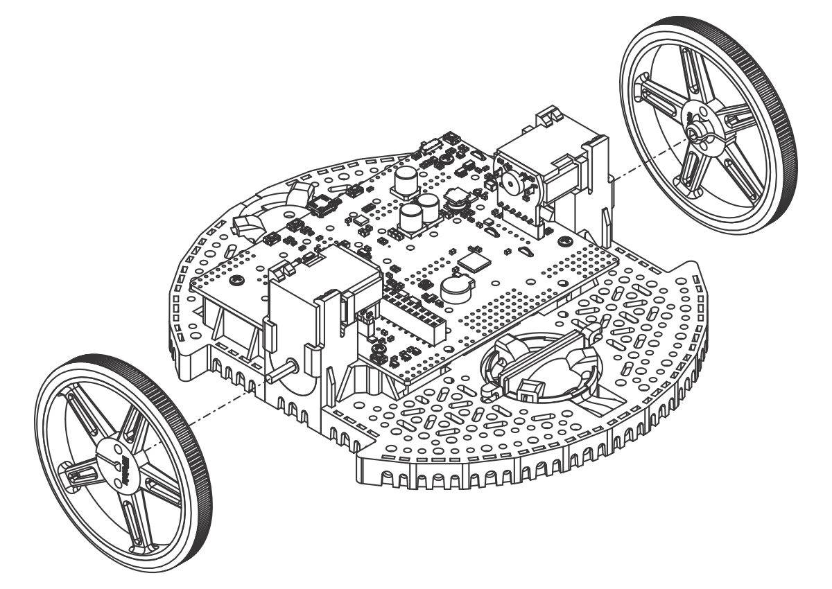
Wheels and ball casters
- Press the wheels onto the output shafts of the motors until the motor shaft is flush with the outer face of the wheel. One way to do this is to set the wheel on a flat surface and line the chassis up with it so that the flat part of the motor’s D-shaft lines up correctly with the wheel. Then, lower the chassis, pressing the motor shaft into the wheel until it contacts the surface.
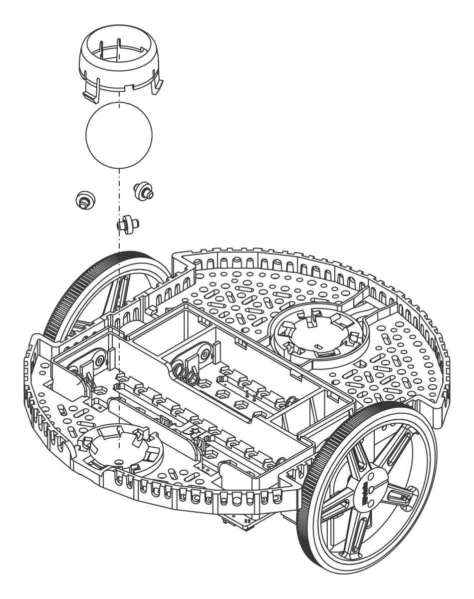
- Flip the chassis upside down and place the three rollers for the rear ball caster into the cutouts in the chassis.
- Place the 1″ plastic ball on top of the three rollers.
- Push the ball caster retention clip over the ball and into the chassis so the three legs snap into their respective holes.
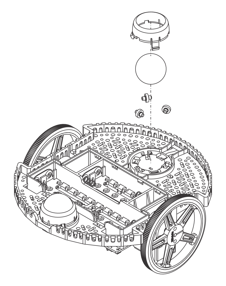
- Optional: Repeat the above steps with the front ball caster socket to install the front ball caster. The Romi Chassis Kit only includes parts for the rear ball caster, but additional Romi Chassis Ball Caster Kits are available separately.
- Optional: The front ball caster is supported by a flexible arm that acts as a suspension system. If you want to make it stiffer, you can wrap a rubber band around the two hooks located on either side of the ball caster on the top side of the chassis.
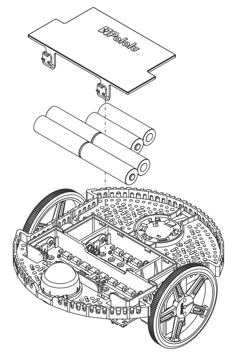
Batteries and battery cover
- The chassis works with four or six AA batteries (we recommend using rechargeable AA NiMH cells). The correct orientation for the batteries is indicated by the battery-shaped holes in the Romi chassis as well as the + and - indicators in the chassis itself. For more information about the various chassis power options, see Section 5.
The assembly of your Romi chassis is now complete!