See Section 1.1 for a diagram to help you identify the contents of the Zumo 32U4 robot kit.
Please follow these instructions carefully to assemble your Zumo 32U4 robot kit properly. If you have an assembled version of the Zumo 32U4 robot, you can skip to Section 5 and start programming it!
Main board additions
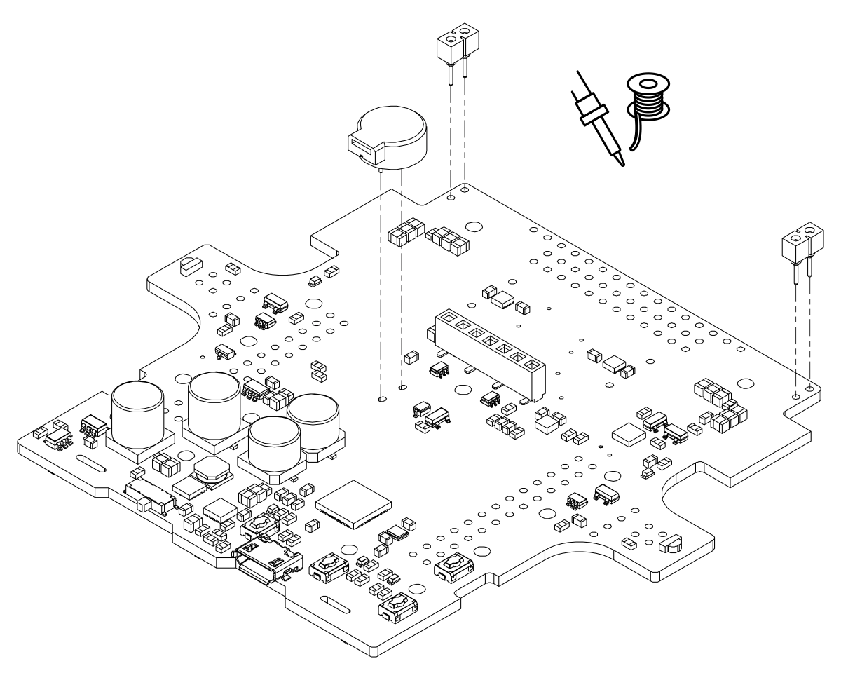
Most of the hardware on the Zumo 32U4 main board consists of surface-mount components that are already soldered to the board, but there are a few through-hole parts that you need to solder yourself.
- Solder the buzzer to the top of the main board, matching its orientation to the printed outline, then trim the excess length from the buzzer leads underneath the board.
- Solder the two 1×2 machine pin sockets to the top of the board in the front corners.
- Optional: If you plan to connect headers or wires to the top expansion area, consider soldering them now.
While it is still possible to solder all of these parts after the main board has been mounted on the chassis, soldering them beforehand is easier and avoids the risk of inadvertently melting the chassis with your soldering iron.
Motors
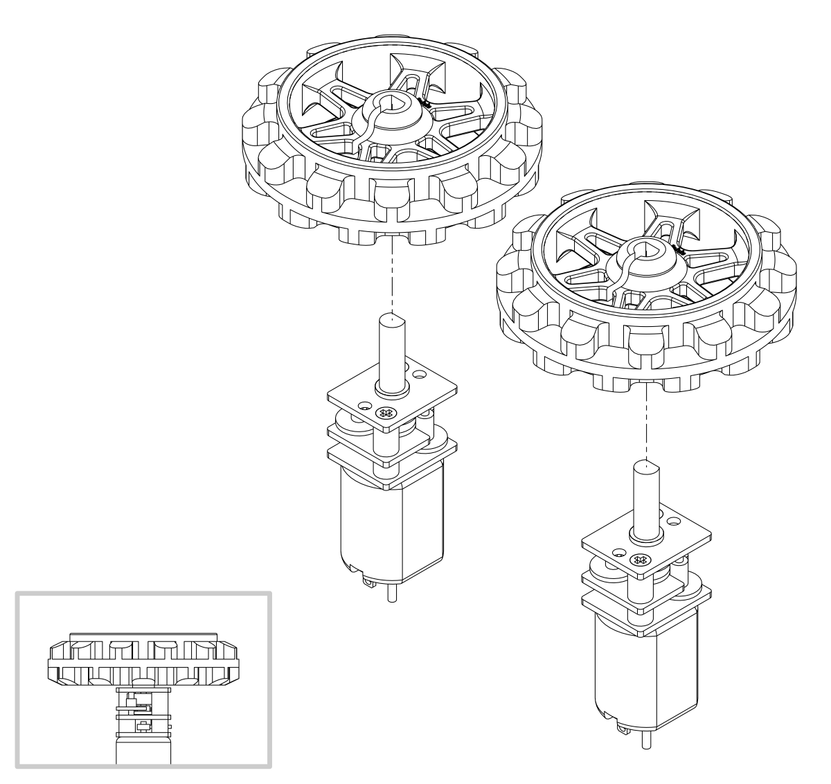
If you have an older Zumo 32U4 kit with white sprockets (which we shipped before May 2015), you should skip step 4 and install the drive sprockets after step 14 instead, at the same time as the idler sprockets. (If the white drive sprockets were attached now, their shape would make the motors, chassis, and main board difficult to assemble.)
- Press the output shafts of the motors into the drive sprockets, with the raised lip on one side of the sprocket facing away from the motor. The end of the gearbox shaft should end up flush with the outside of the sprocket. A good way to do this is to set the wheel on flat surface (like a table top) and press the motor shaft into the wheel until it contacts the surface.
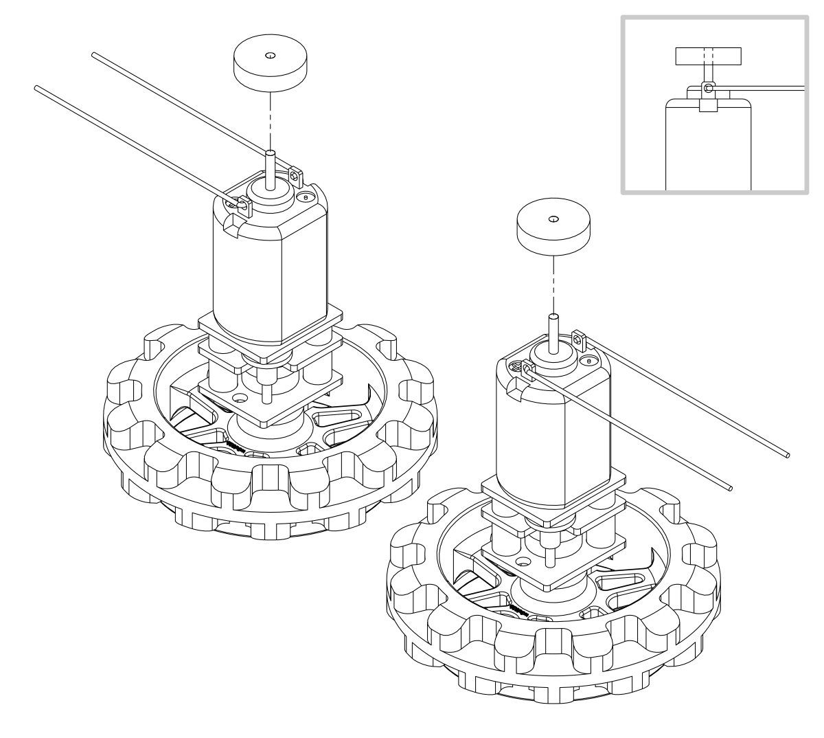
- Cut two of the included jumper wires in half to form four segments, and trim off the ends that are covered in adhesive (the adhesive could interfere with making a good electrical connection to the motor). These wire segments will be used as motor leads.
- Solder a pair of leads to each motor, paying attention to the way the motor will eventually be oriented in the chassis (see below). You might find it helpful to make a small bend at the tip of each lead to hook into the hole in the motor lead tab to hold it in place for soldering.
Warning: Holding the soldering iron against the motor lead for more than a few seconds can start to damage the motor brushes, so try to be reasonably quick/efficient with this soldering. If the first attempt does not go well, remove the soldering iron and let the motor cool for a few seconds before trying again.
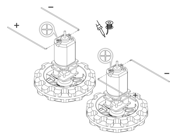 |
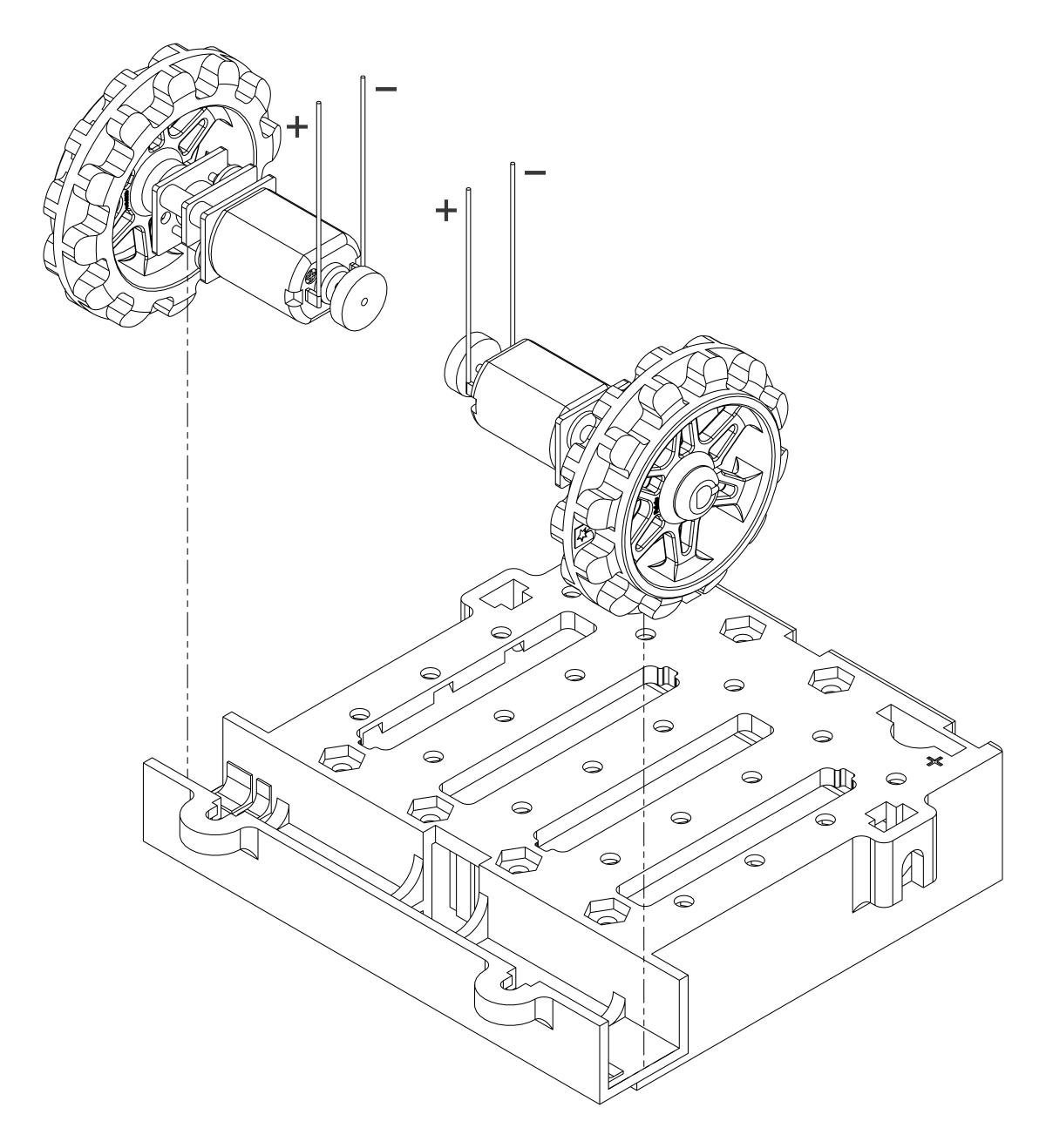
Each motor’s positive terminal is indicated by a plus sign (+) in the black plastic end of the motor. If you are using one of our recommended micro metal gearmotors (50:1, 75:1, or 100:1) or any lower gear ratio, the motors should be soldered into the main board with the positive terminal closest to the front, so you should attach the leads to allow the motors to be oriented this way. However, if you are using a motor with a 150:1 or higher gear ratio, you should reverse the motor orientation so the positive terminals are facing the rear. (Don’t worry if you accidentally get the orientation of one or both motors wrong, though. You can later correct for it in software with our Zumo32U4 library.)
- Press a magnetic encoder disc onto the motor shaft of each motor so that the end of the shaft is flush with the back of the disc. One easy way to accomplish this is to press the motor onto the disc while the disc is sitting on a flat surface, pushing until the shaft makes contact with that surface.
Chassis
- Place the motors into the channel in the front of the chassis, aligning the gearbox with the grooves in the channel. The outer plate of the gearbox should be even with the edge of the chassis.
- Cover the chassis and motors with the main board. The motor leads should be inserted into the through holes next to the motor drivers.
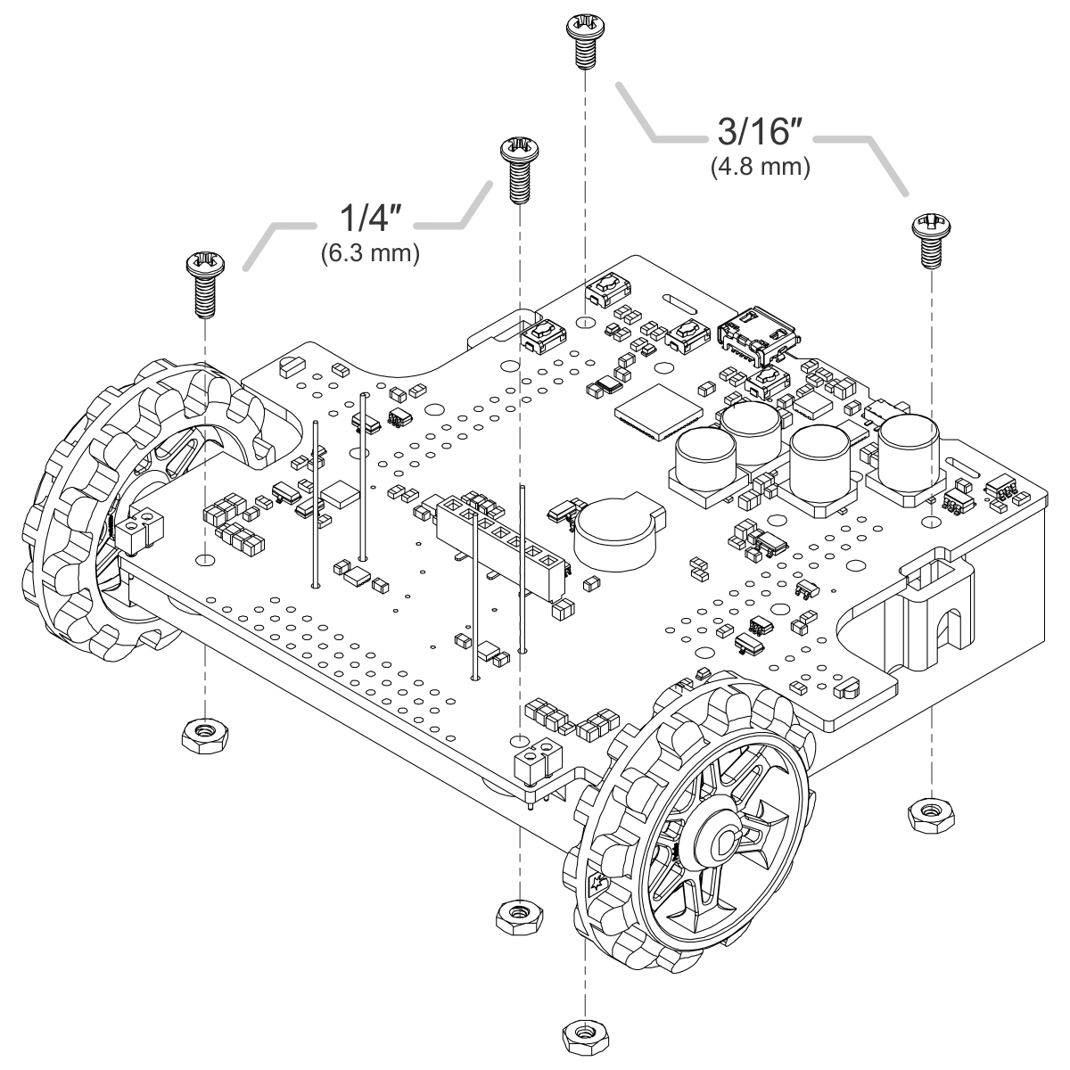
- Screw the main board to the chassis: we recommend using four screws in the holes closest to the corners of the board. In each of the four mounting holes, insert a #2-56 machine screw through the main board and chassis, and tighten it against a nut under the chassis. It is usually easier to place the nut into the recess first and hold it there with a finger or piece of tape while inserting the screw.
Note that the kit includes two different sizes of #2-56 machine screws: 3/16″ and 1/4″. The two longer screws are intended for use in the front holes (near the motors) so that the additional thickness of a sumo blade can be accommodated. While you can add the blade before screwing the robot together for the first time, we suggest waiting until after you have soldered in the 2×12 connector for the front sensor array so that you have more room to work.
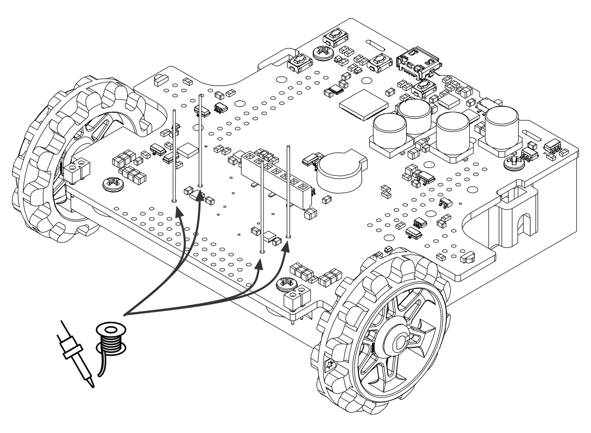
- Solder each motor lead to the main board, then trim off the excess length of wire.
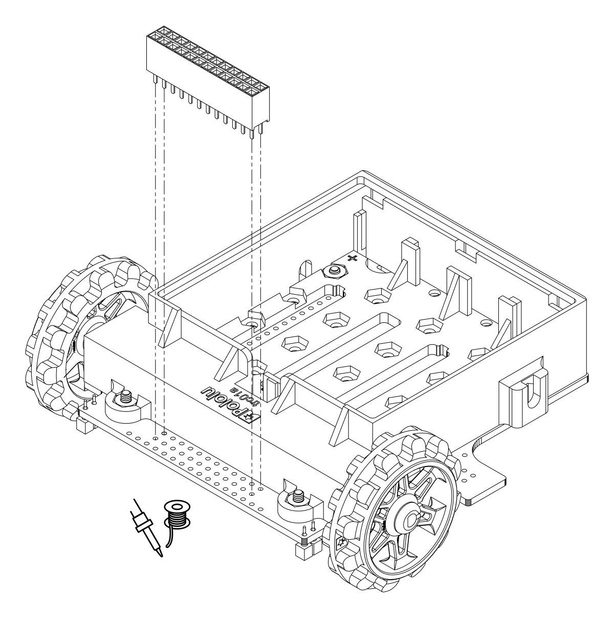
- Solder the 2×12 female header (front sensor array connector) to the bottom of the front expansion area on the main board. It should be flush with the chassis.
Battery contacts
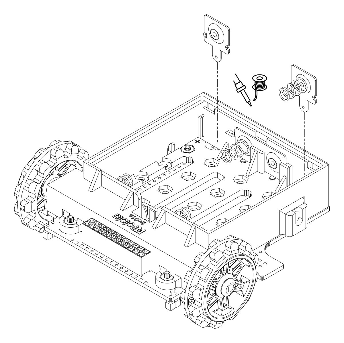
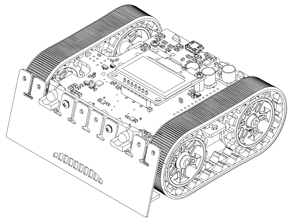
- Turn the chassis over and install the battery terminal contacts as shown in the pictures below. The three double-contact pieces should be firmly pressed into place until they are flush with the interior surface of the battery compartment.
Note: there are two different kinds of double-sided battery contacts, one with the spring on the left and one with the spring on the right, and they must be installed in the correct locations to make proper contact with the batteries.
The two individual contacts should be inserted into the battery compartment so that their solder tabs protrude through the holes in the top of the chassis; you might want to temporarily tape or clamp these two individual contacts in place until they have been soldered to the main board as described in the next step, or you can use a battery to temporarily hold them in place.
- Solder the two individual contacts to the main board from the top. Note that if you are using a battery to hold the contact in place during soldering, the battery might act as a heat sink, making it more difficult to solder or requiring a higher soldering iron temperature. The battery terminal slot in the PCB should be completely filled with solder.
Idler sprockets and tracks
- Place an M3 nut in each of the two side slots near the rear of the chassis. The slots are sized so that nuts will not be able to rotate within them.
- Place an idler sprocket on each shoulder bolt, followed by a washer. The protruding side of the sprocket hub should face the same direction as the threaded end of the bolt (in toward the chassis).
- Insert the shoulder bolts through the side of the chassis into the nut. Use a 3 mm hex key (Allen wrench) to tighten the bolts until the washers are snug against the chassis. Be careful not to overtighten the shoulder bolts as doing so can bend the washers. Note: Be careful if you use threadlocking adhesives like Loctite as these can corrode the chassis. You should first test any such adhesives on a concealed part of the chassis to ensure they will not damage it.
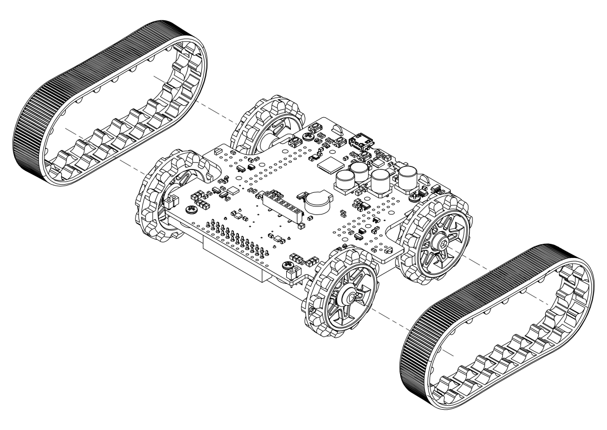
- Install the silicone tracks by stretching them around the sprockets on each side of the chassis.
Blade
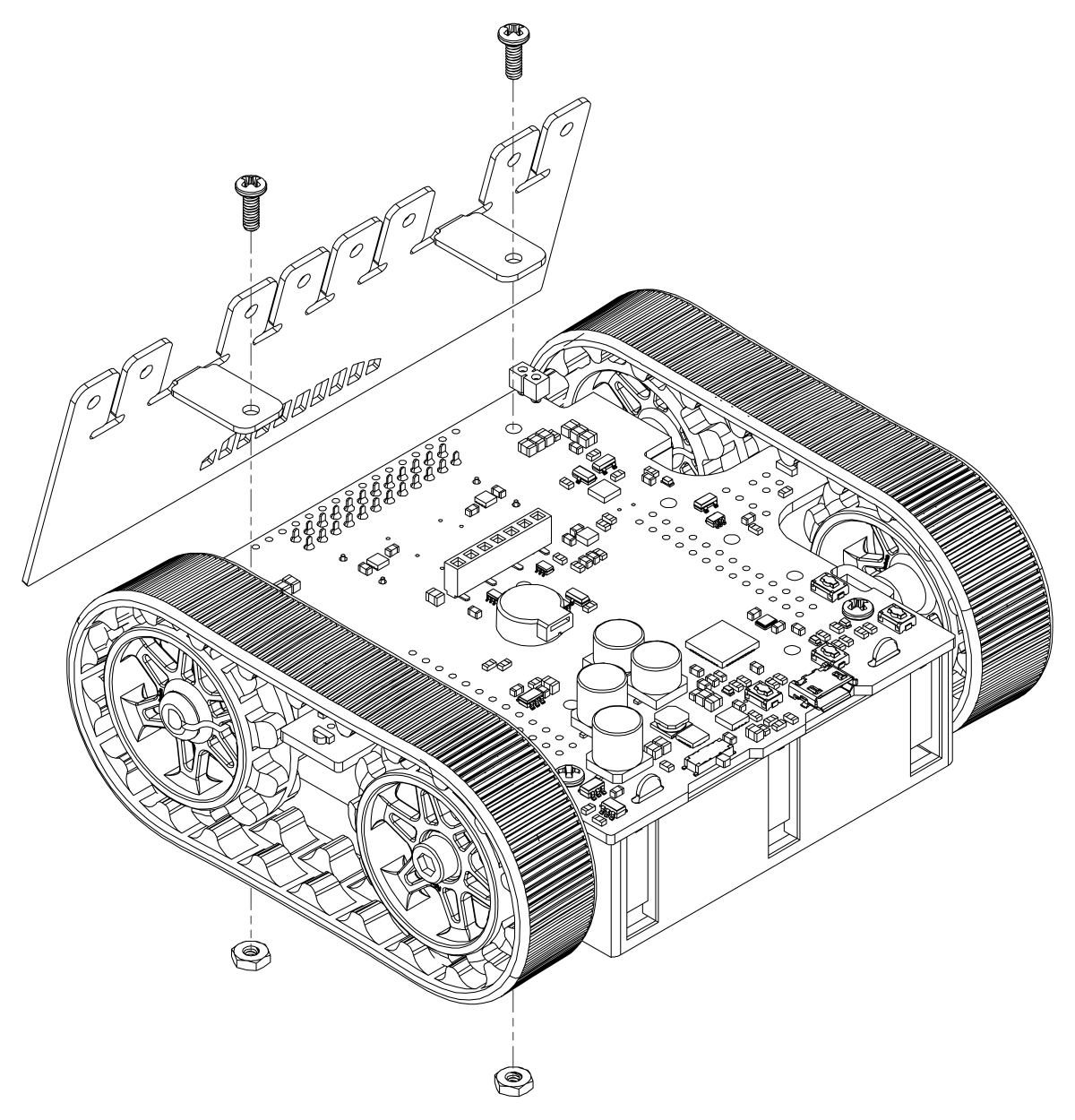
- If necessary, bend the blade’s mounting tabs to the appropriate angle (about 75 degrees from flat).
- Remove the two 1/4″ screws attaching the front of the main board to the chassis.
- Place the blade’s mounting tabs on top of the main board so that the holes line up with the two front mounting holes and the two screws through the blade, main board, and chassis. Replace the nuts underneath the chassis and tighten the screws.
Display
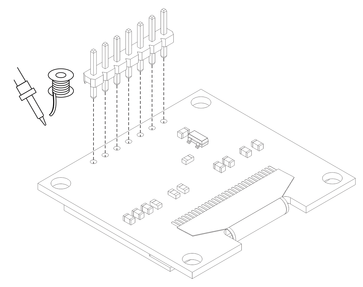
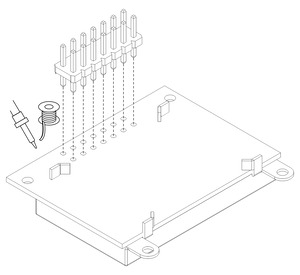
- Solder the 1×7 low-profile header to the OLED display (or the 2×7 low-profile header to the LCD). The shorter side of the header should be inserted fully through the corresponding through holes from the bottom side of the display module until the header is flush, and the solder joints should be made on the top (screen) side of the display. Tip: Solder a single pin first and ensure the header is flush before making any additional solder joints. If the header is not flush, you can use the soldering iron to re-melt the solder joint while you make the necessary adjustments. Be careful not to touch the pin you are soldering as the heat will conduct all the way through to the other end!
 | Installing header pins on the OLED display. |
|---|
|
 | Installing header pins on the LCD. |
|---|
|
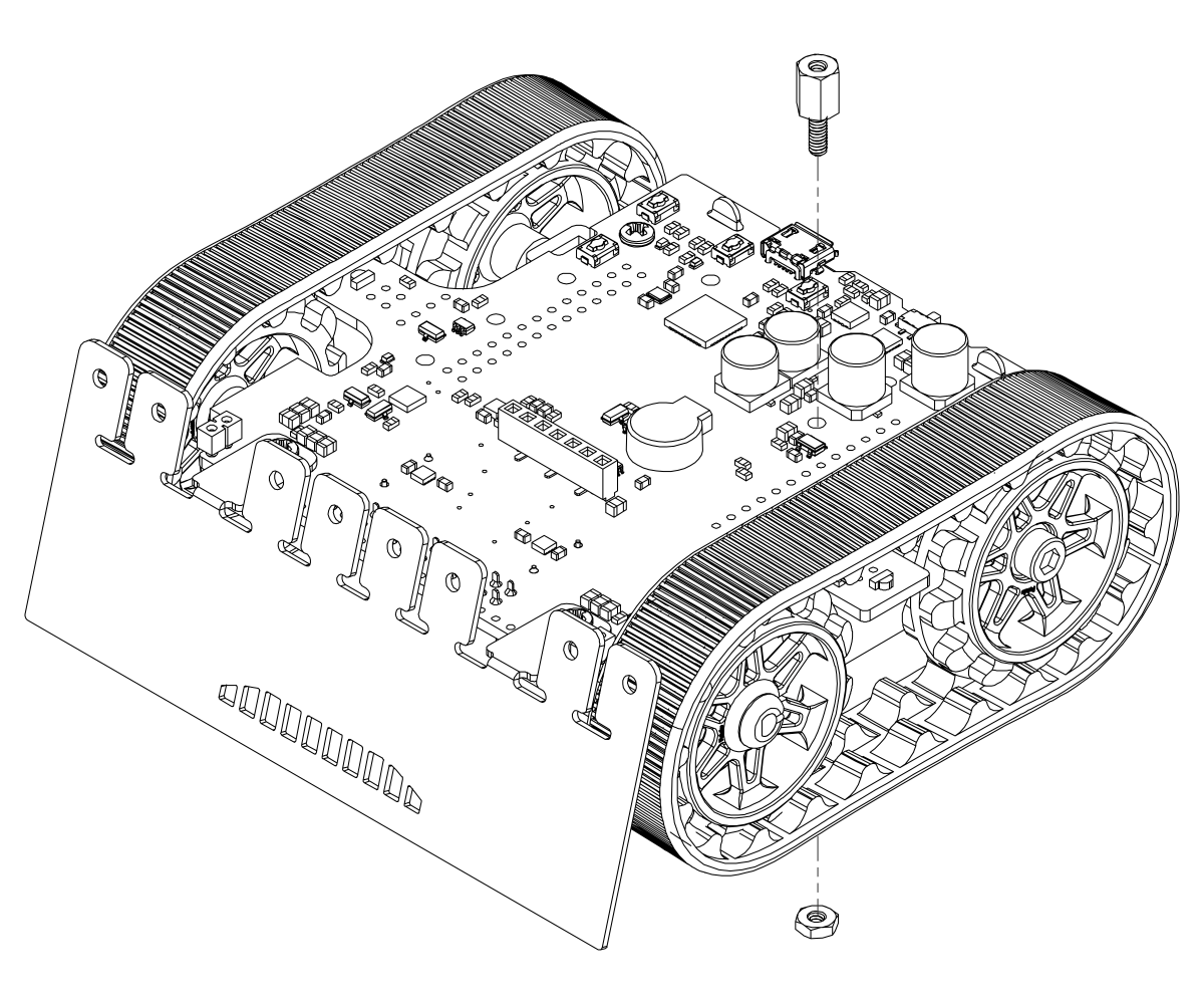
- On the Zumo 32U4 OLED version, you can optionally install a #2-56 standoff to help support the OLED display. Tighten the standoff against a nut under the chassis.
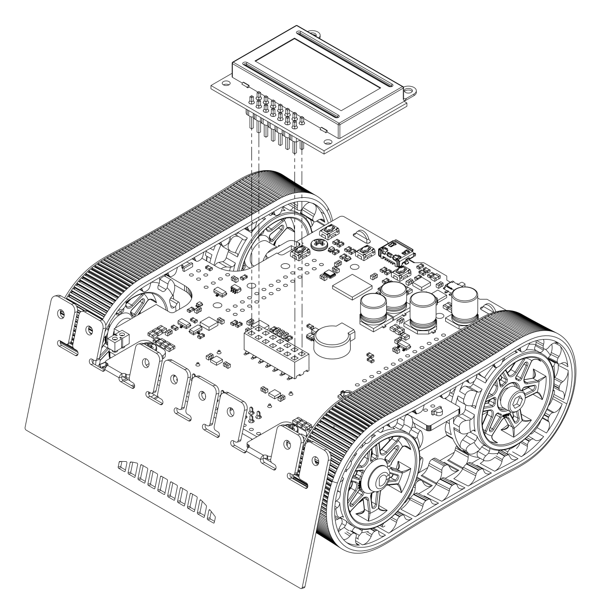
- Plug the display into the matching female header on top of the main board; the display should cover the buzzer. You can optionally use one more 3/16″ #2-56 screw to secure the OLED display to the standoff.
Warning: The display header does not enforce proper orientation, so it is possible to plug the display in offset or rotated 180° from its intended position. Incorrect positioning can damage the display or the main board, so please take care during this step to ensure that the display is plugged in properly.
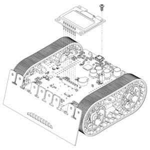 | Mounting the Zumo 32U4 OLED display. |
|---|
|
 | Mounting the Zumo 32U4 LCD. |
|---|
|
Front sensor array
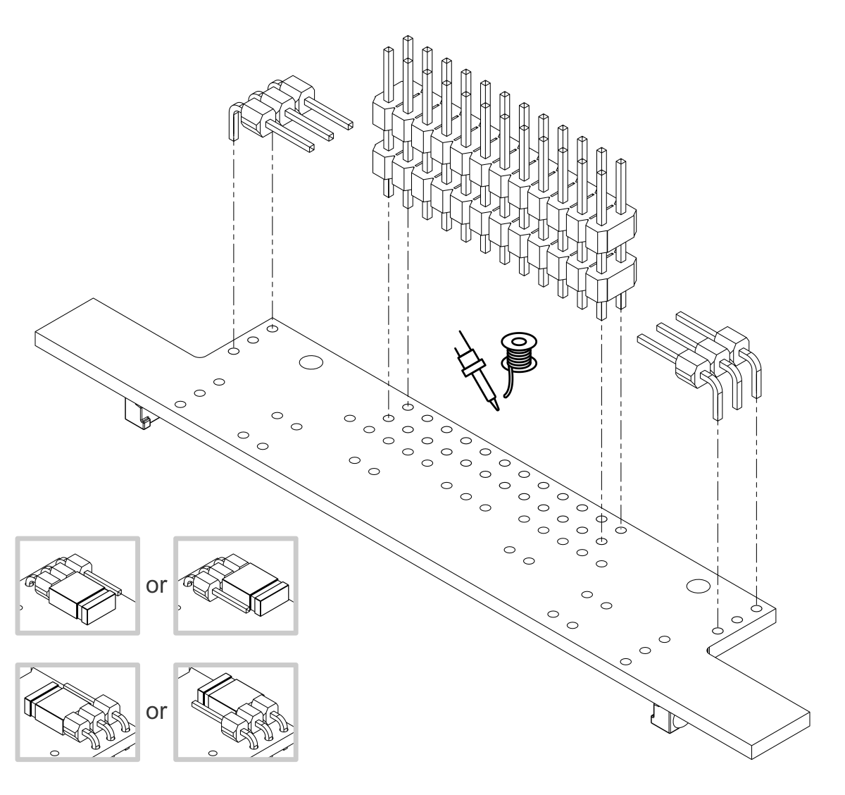
- Solder the two 1×3 right-angle male headers on top of the sensor array board. These should go in the two sets of three holes in the rear corners of the board, and the pins should face inward. Note: these pins go on the side of the board without components.
- Solder the 2×12 extended male header to the top of the sensor array. Note: these pins also go on the side of the board without components, so that the sensors point at the ground when the board is plugged into the Zumo; if you solder this header on the wrong side, the sensor array will not work!
- On each 1×3 header, install a shorting block to connect the sensor of your choice. (See Section 3.5 for details.)
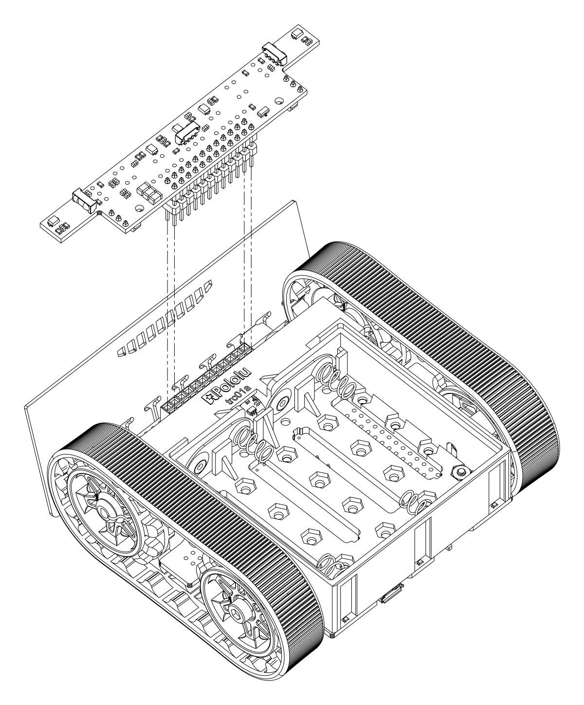
- Plug the sensor array into the matching female header on the bottom of the main board.
Forward emitters
- Choose a pair of through-hole infrared LEDs to use as the forward emitters. (See Section 3.6 for details about the different LEDs included with the Zumo 32U4.)
The forward IR emitter LEDs can be installed using the plastic LED holder, which we recommend using in most cases (continue to step 30). Alternatively, they can be installed without the LED holder using heat shrink tubing as shrouds; this mounts them less securely, but allows some more flexibility in their positioning (skip to step 35).
Note: Kits shipped before August 2015 do not include the LED holder and its mounting screws.
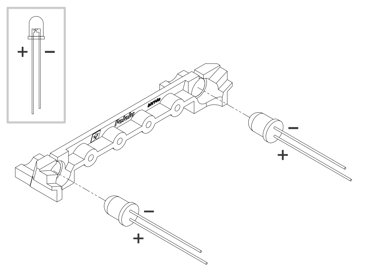
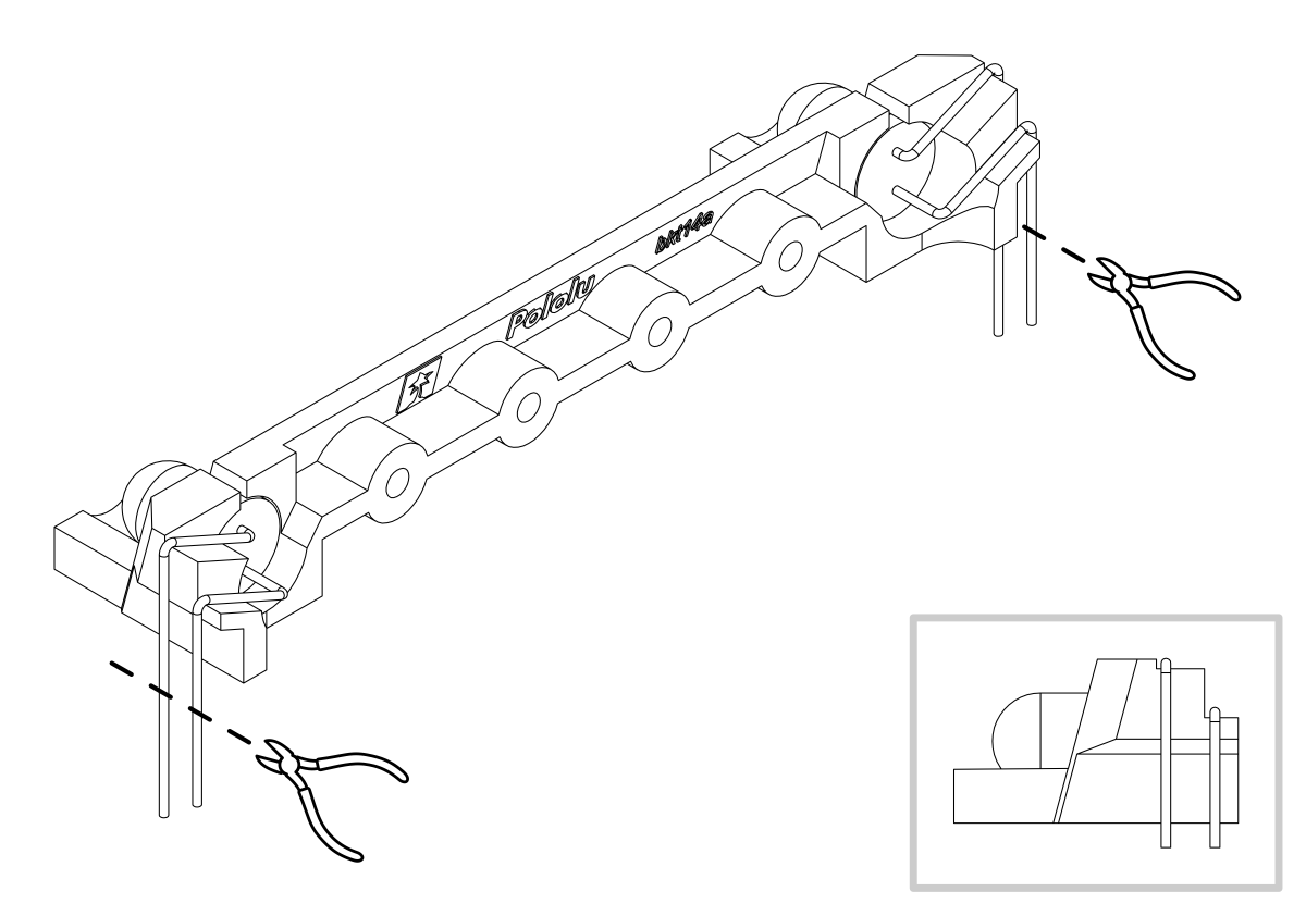
- Insert the LEDs into the rear of the LED holder, making sure that each LED’s anode (the longer lead that ends in the smaller post inside the case of the LED) is on the bottom.
- Bend the LED leads outward so they rest along the channels in the LED holder, then downward around the sides of the holder. Using a pair of long-nose pliers can help you make more precise bends.
- Trim the LED leads so that they extend slightly below the bottom of the LED holder.
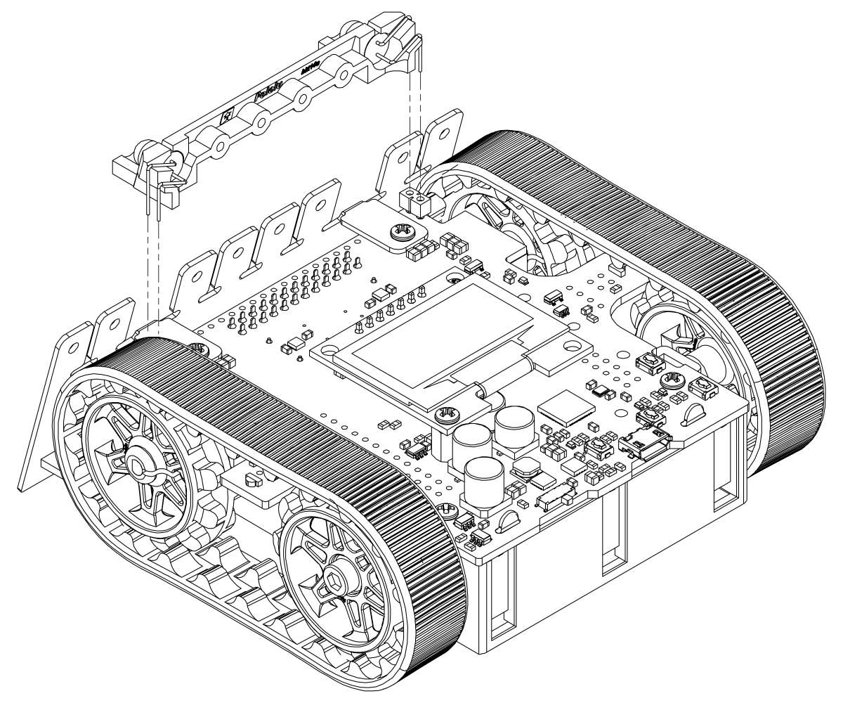
- Install the LED holder behind the blade by inserting the LED leads into the machine pin sockets in the front of the main board.
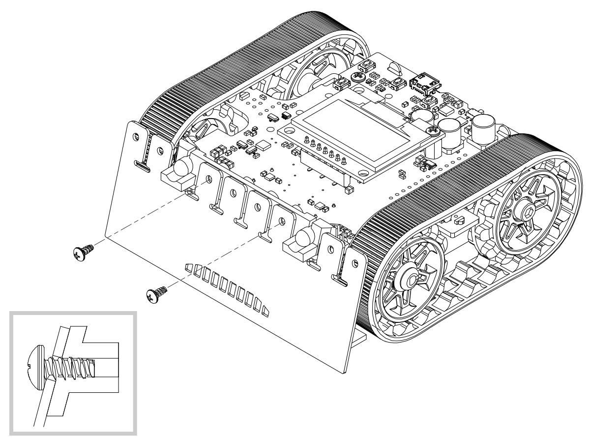
- Use two 3/16″ #2-28 thread-forming screws to fasten the LED holder to the blade. Note that the screw heads will not be completely flush against the blade when properly tightened; to avoid damaging the LED holder, do not overtighten the screws!
To finish assembly after installing the forward emitters with the LED holder, skip to step 40.
Forward emitters – alternate method (without LED holder)
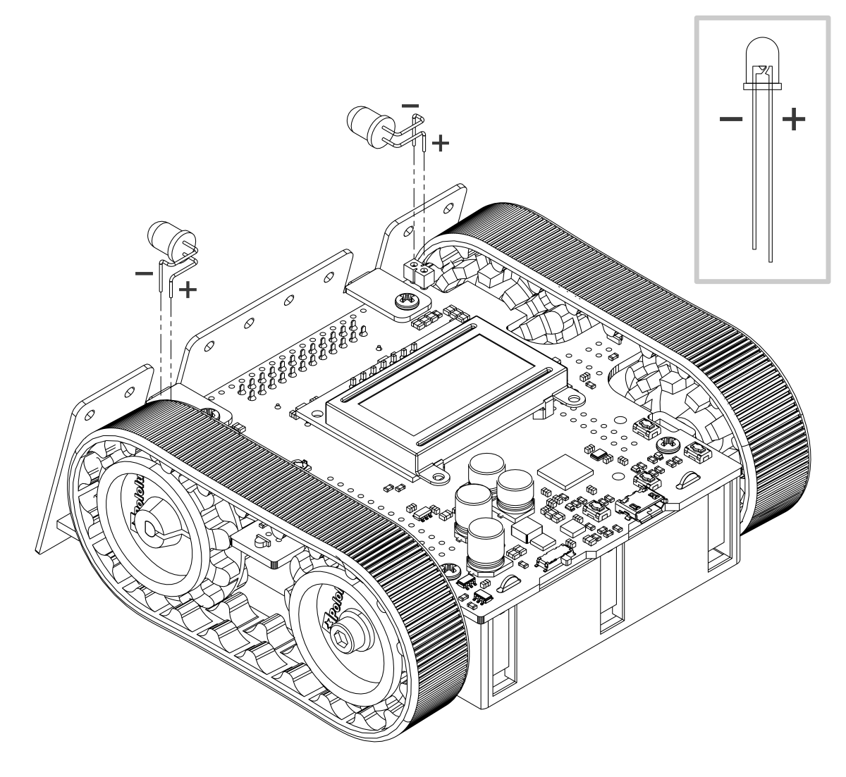
- Use a pair of long-nose pliers to bend the LED leads to approximately match the shapes pictured, making sure that each LED’s anode (the longer lead that ends in the smaller post inside the case of the LED) is toward the rear.
- Trim the excess length from the leads and insert the LEDs into the machine pin sockets in the front of the main board.
 |
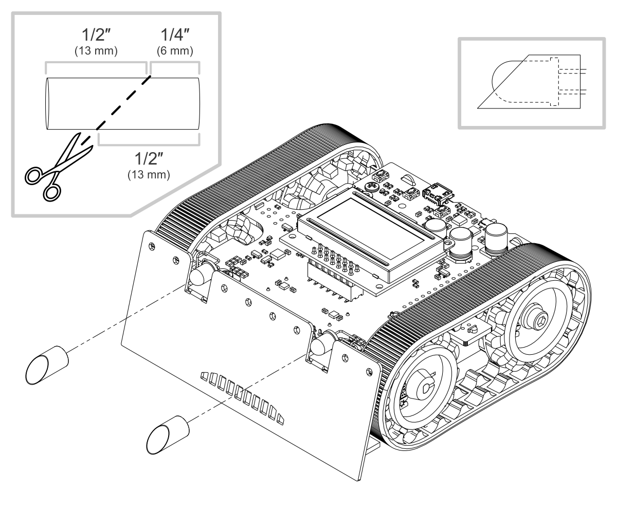
- Cut a length of heat shrink tubing about 3/4″ (19 mm) long. 3/16″ diameter heat shrink tubing can work well (we included tubing of this size with kits prior to August 2015), but please note that the actual diameter of heat shrink tubing often differs significantly from its nominal diameter, depending on the type and manufacturer of the tubing.
- Flatten the tube and make a diagonal cut through it to produce two equal pieces. Each piece should measure about 1/2″ (13 mm) along the longer side.
- Slip one of these pieces of heat shrink tubing, square end first, over each forward emitter LED so that it extends past the case of the LED. The diagonal opening of each tube should face forward and upward so that the longer side of the shroud blocks infrared light from hitting the floor.
Batteries
- Install four new or freshly charged AA batteries in the battery compartment. (We recommend using rechargeable AA NiMH cells.)
- Replace the battery compartment cover.
The assembly of your Zumo 32U4 robot is now complete, and it is ready to be programmed and run!