TI Robotics System Learning Kit MAX (TI-RSLK MAX) Parts and Accessories »
Pololu Chassis Kit for TI-RSLK MAX

Note: This product is Pololu’s portion of the TI-RSLK Robot, which is a Texas Instruments product that TI is no longer supporting. We are continuing to make the chassis kit available for those who need replacement parts for their existing TI-RSLK robots, but we do not recommend it for new applications.
This is Pololu’s portion of Texas Instruments Robotics System Learning Kit (TI-RSLK) MAX. A TI MSP432P401R LaunchPad with custom-soldered headers (not included) is required to complete the robot.
 Compare all products in TI Robotics System Learning Kit MAX (TI-RSLK MAX) Parts and Accessories.
| Description | Specs (2) | Pictures (14) | Resources (8) | FAQs (0) | On the blog (0) | Distributors (1) |
|---|
Overview
 |
This kit consists of the following products, most of which are also available for purchase separately as replacements:
- Black Romi Chassis Kit (but with red wheels instead of white)
- TI-RSLK Chassis Board v1.0 for TI-RSLK MAX
- 8-Channel QTRX Sensor Array for Romi/TI-RSLK MAX (Through-Hole Pins Soldered)
- Left Bumper Switch Assembly for Romi/TI-RSLK MAX (Through-Hole Pins Soldered)
- Right Bumper Switch Assembly for Romi/TI-RSLK MAX (Through-Hole Pins Soldered)
- 2× Gearmotor and Encoder Assembly for Romi/TI-RSLK MAX
- Pololu 400-Point Breadboard with Mounting Holes and four 1″-long #2-56 M-F aluminum standoffs (with screws and nuts for mounting)
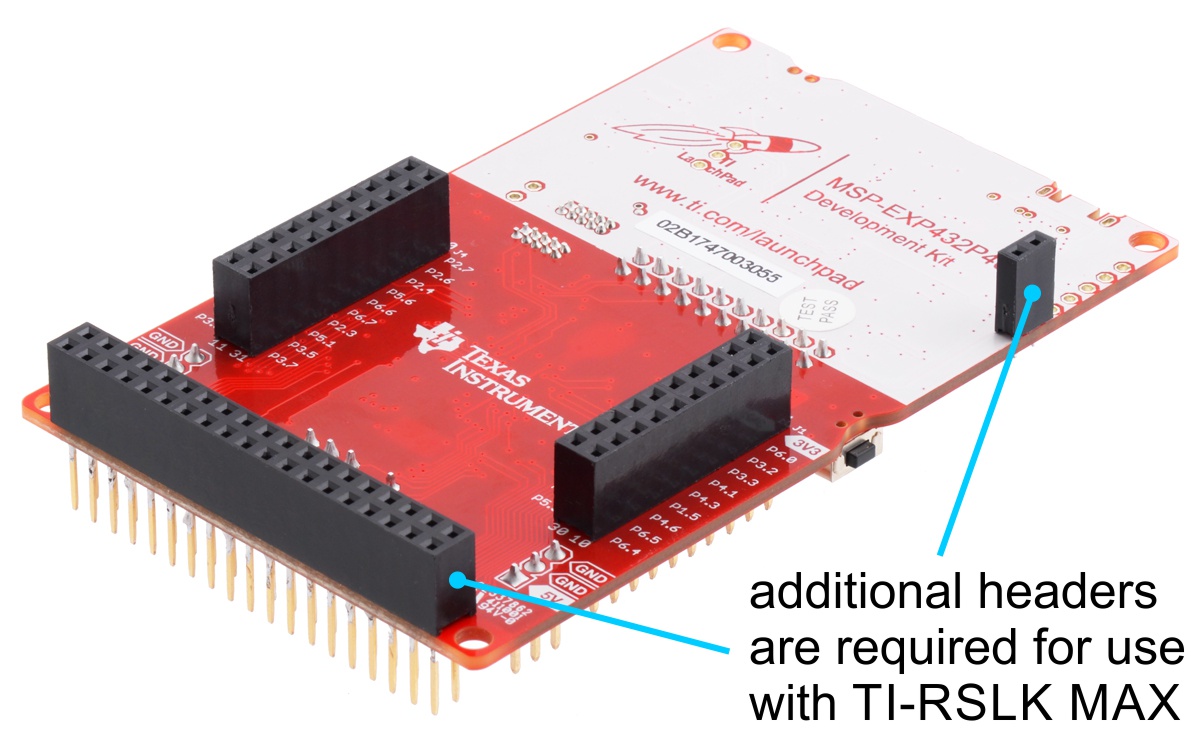
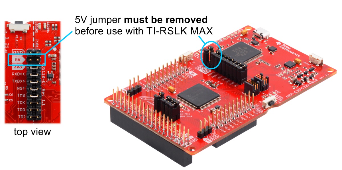
Note: This kit does not include a TI MSP432P401R LaunchPad, which is required to complete the TI-RSLK MAX robot. The LaunchPad must be specially assembled with a 2×19 stackable female header and a 1×2 female header so that it can plug into the Chassis Board, and the LauchPad’s 5V jumper must be removed prior to use with TI-RSLK MAX in order to avoid shorting different power rails and potentially damaging the Chassis Board. A properly assembled LaunchPad is included with the complete TI-RSLK MAX kit from Texas Instruments, and we also have them available separately.
 |
 |
Assembly instructions
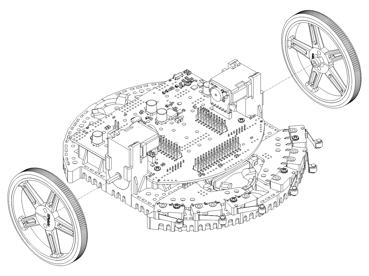
Click on the picture below for step-by-step assembly instructions:
We also have a short assembly video:
Optional accessories
- Robot Arm Kit for Romi for adding object manipulation capabilities to the TI-RSLK MAX robot (note: the optional front ball caster listed below is highly recommended when adding the Robot Arm)
- Romi Chassis Ball Caster Kit for use with the Romi front ball caster option
- Sharp Distance Sensor Kit for Romi/TI-RSLK MAX for adding obstacle detection and ranging
- Romi Chassis parts in other colors for customizing the look of your TI-RSLK MAX robot
- Rechargeable NiMH AA batteries (the Romi chassis requires six AA batteries)
Pinout diagram of the TI-RSLK Chassis Board
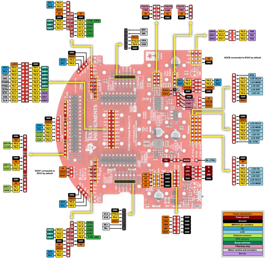 |
This diagram is also available as a downloadable pdf (475k pdf).
Operating voltage range
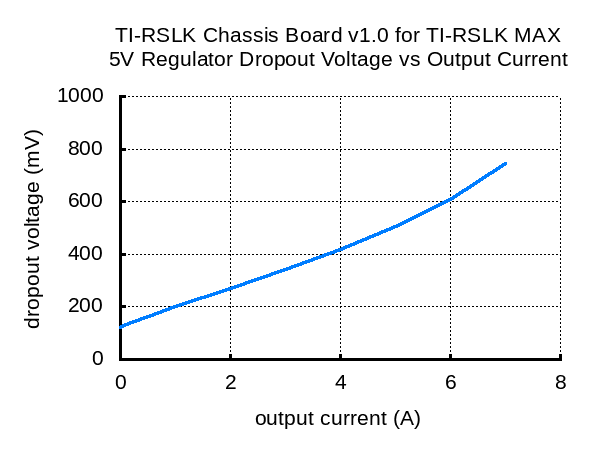
The TI-RSLK Chassis Board v1.0 for TI-RSLK MAX is generally intended to be powered by six AA batteries, either alkaline or rechargeable, but the board can handle input voltages up to 10.8 V. The minimum input voltage is subject to the dropout voltage characteristics of the on-board 5 V switching regulator, which depend on the load on the 5V rail as shown in the dropout voltage graph below. With no additional load on the 5V rail, the minimum input needed to get 5 V out is about 5.2 V. This increases approximately linearly to around 5.8 V with 7 A of load.
 |
Note that none of the features of the TI-RSLK MAX actually need the 5V rail to be at 5 V, so if nothing else sensitive is connected to that rail, the input voltage to the chassis board can drop as low as 4.5 V before the board stops functioning.
Power
The TI-RSLK Chassis Board includes battery terminal connections that provide access to power from the chassis’s six-AA battery compartment. We recommend using rechargeable AA NiMH cells, which results in a nominal voltage of 7.2 V (1.2 V per cell). You can also use alkaline cells, which would nominally give you 9 V.
The negative battery voltage is connected to GND. The positive battery voltage is designated VBAT. VBAT feeds into a reverse protection circuit and then a power switching circuit controlled by the on-board pushbutton or slide switch. The output of the power switching circuit is designated VSW.
VSW provides power to the motors through the on-board DRV8838 motor drivers, so the motors can only operate if the batteries are installed and the power switch circuit is on.
Power switch circuit
TI-RSLK Chassis Board uses the patented latching circuit from the Pololu pushbutton power switch, which provides a solid-state power switch for your robot controlled with the on-board pushbutton. By default, this pushbutton can be used to toggle power: one push turns on power and another turns it off. Alternatively, a separate pushbutton can be connected to the A and B pins and used instead. Multiple pushbuttons can be wired in parallel for multiple control points, and each of the parallel pushbuttons, including the one on the board itself, will be able to turn the switch on or off. The latching circuit performs some button debouncing, but pushbuttons with excessive bouncing (several ms) might not function well with it.
For proper pushbutton operation, the board’s slide switch should be left in its Off position. (Sliding the switch to the On position will cause the board power to latch on, and the switch must be returned to the Off position before the board can be turned off with the pushbutton.)
Alternatively, to disable the pushbutton, you can cut the button jumper labeled Btn Jmp; this transfers control of the board’s power to the on-board slide switch instead. A separate slide or toggle switch can be connected to the SW pin and used instead.
The power switch circuit also offers several alternate pushbutton connection options that result in push-on-only or push-off-only operation, and additional inputs enable further power control options like allowing your robot to turn off its own power. These advanced control options are available through the button connection pins and four control inputs:
| PIN | Description |
|---|---|
| A | Connect through momentary switch to pin “B” for standard push-on/push-off operation. Connect through momentary switch to ground for on-only operation. |
| B | Connect through momentary switch to pin “A” for standard push-on/push-off operation. |
| ON | A high pulse (> 1 V) on this pin turns on the switch circuit. This pin only functions when pushbutton operation is enabled (i.e. the button jumper has not been cut). |
| OFF | A high pulse (> 1 V) on this pin turns off the switch circuit (e.g. allowing a powered device to shut off its own power). This pin only functions when pushbutton operation is enabled. |
| CTRL | With pushbutton operation enabled, this pin directly determines the state of the switch circuit. A high pulse (> 1 V) on this pin turns on the switch; a low pulse (e.g. driving the pin low with a microcontroller output line or pushing a button connected from this pin to ground) turns the switch off. Leave this pin disconnected or floating when not trying to set the switch state. Note that this pin should not be driven high at the same time the “OFF” pin is driven high. |
| SW | With pushbutton operation disabled (button jumper cut), this pin controls the state of the switch circuit: driving it low turns the switch on, while letting it float turns the switch off. Connect through slide or toggle switch to ground for on/off operation. Leave this pin disconnected or floating for proper pushbutton operation. We recommend only ever driving this pin low or leaving it floating; this pin should never be driven high while the slide switch is in the “On” position. |
Related products


Home | Forum | Blog | Support | Ordering Information | Lists | Distributors | BIG Order Form | About | Contact
© 2001–2026 Pololu Corporation
