This guide explains how to assemble the TI-RSLK MAX Kit. A TI MSP432P401R LaunchPad specially assembled with headers for plugging into the Chassis Board is required to complete the robot; this is not included as part of item #3670. Before beginning, you might also want to watch our short assembly video:
Main board
Steps 1-4 are only necessary if your TI-RSLK MAX Chassis Board is not already installed on your Romi chassis. If it is already installed, you can skip to step 5.
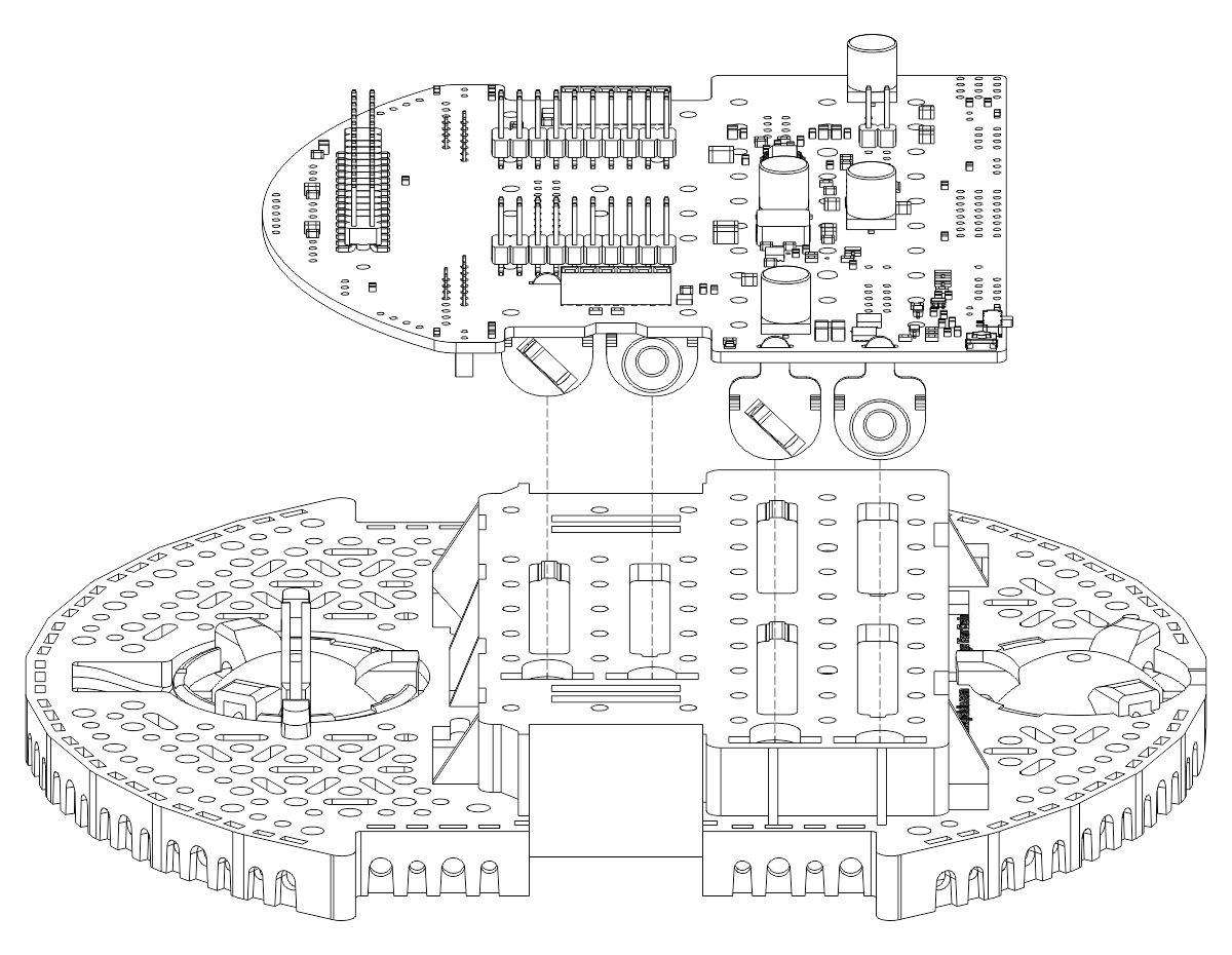
- Place the main board on the chassis, being careful to feed the pre-soldered battery contacts through the cutouts in the chassis. You will need to compress the springs to get them to insert correctly. One method of doing this that might make things easier is to use a small screwdriver to reach through the underside of the chassis and compress the spring while lowering the board into position. Ensure the battery contacts align with the slots in the chassis as shown below:
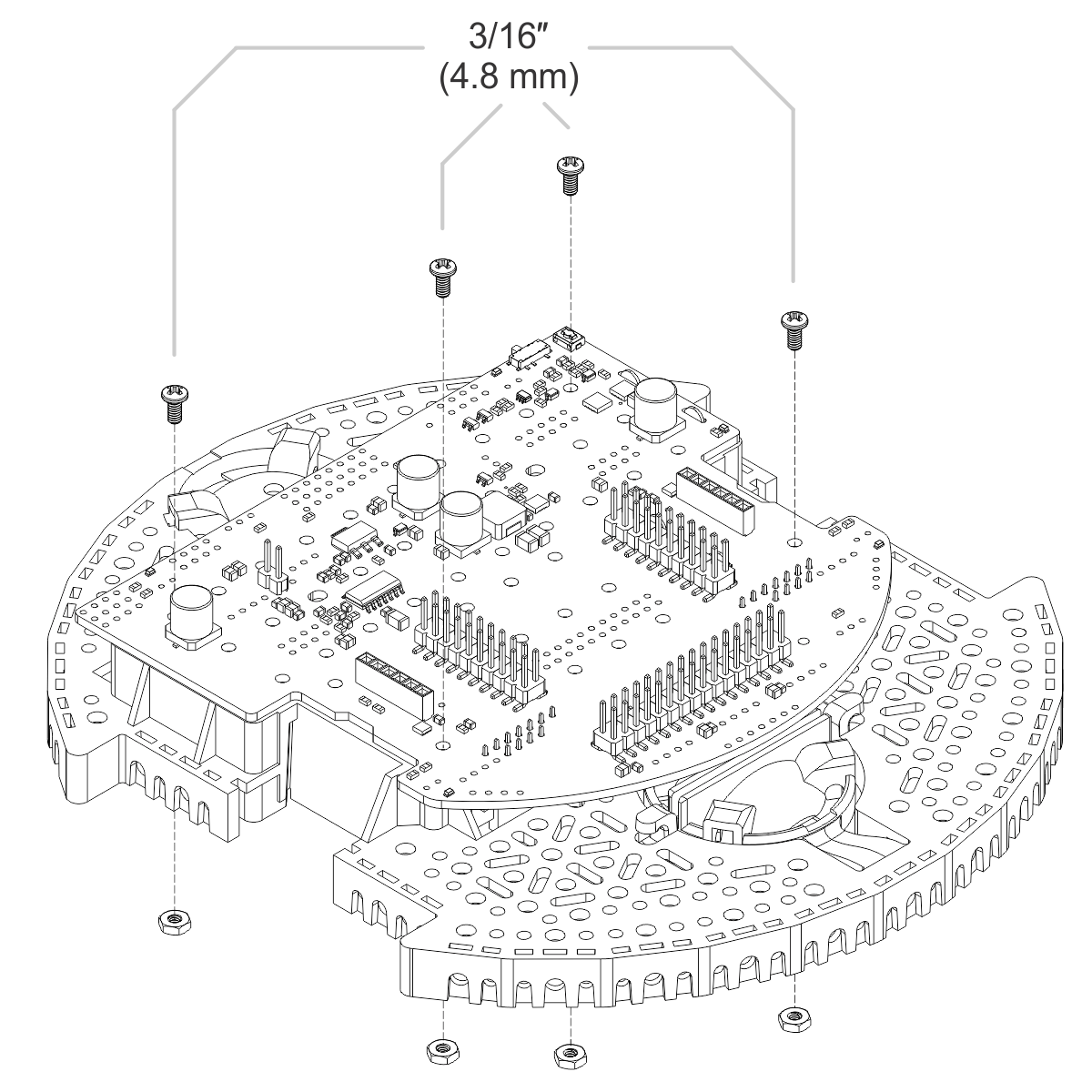
- Use four 3/16″ length, #2-56 screws to secure the PCB to the top of the battery compartment.
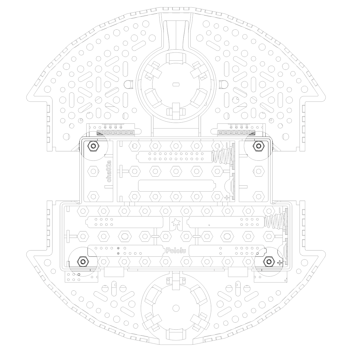
- Ensure the four #2-56 nuts are seated into the appropriate cutouts in the underside of the battery compartment.
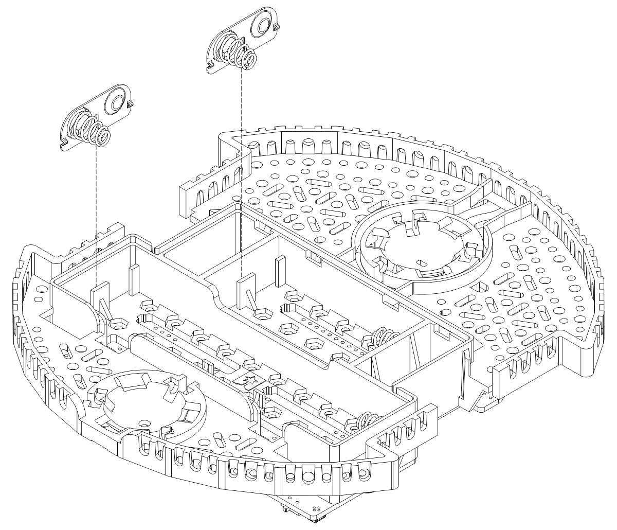
- With the chassis upside down, push the two double-sided battery contacts into the slots indicated in the picture below.
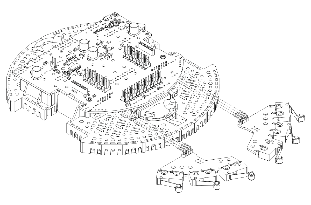
Bumper switch boards
It is probably easier to fully install one bumper switch board before starting to install the second, but the diagrams below show both boards being installed simultaneously for brevity.
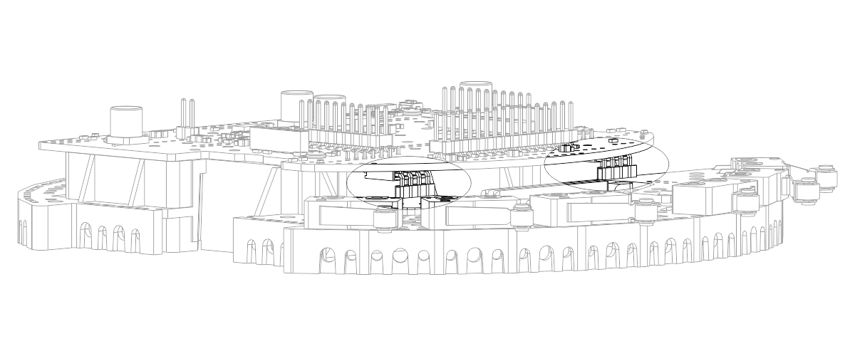
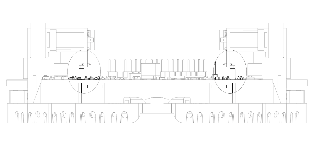
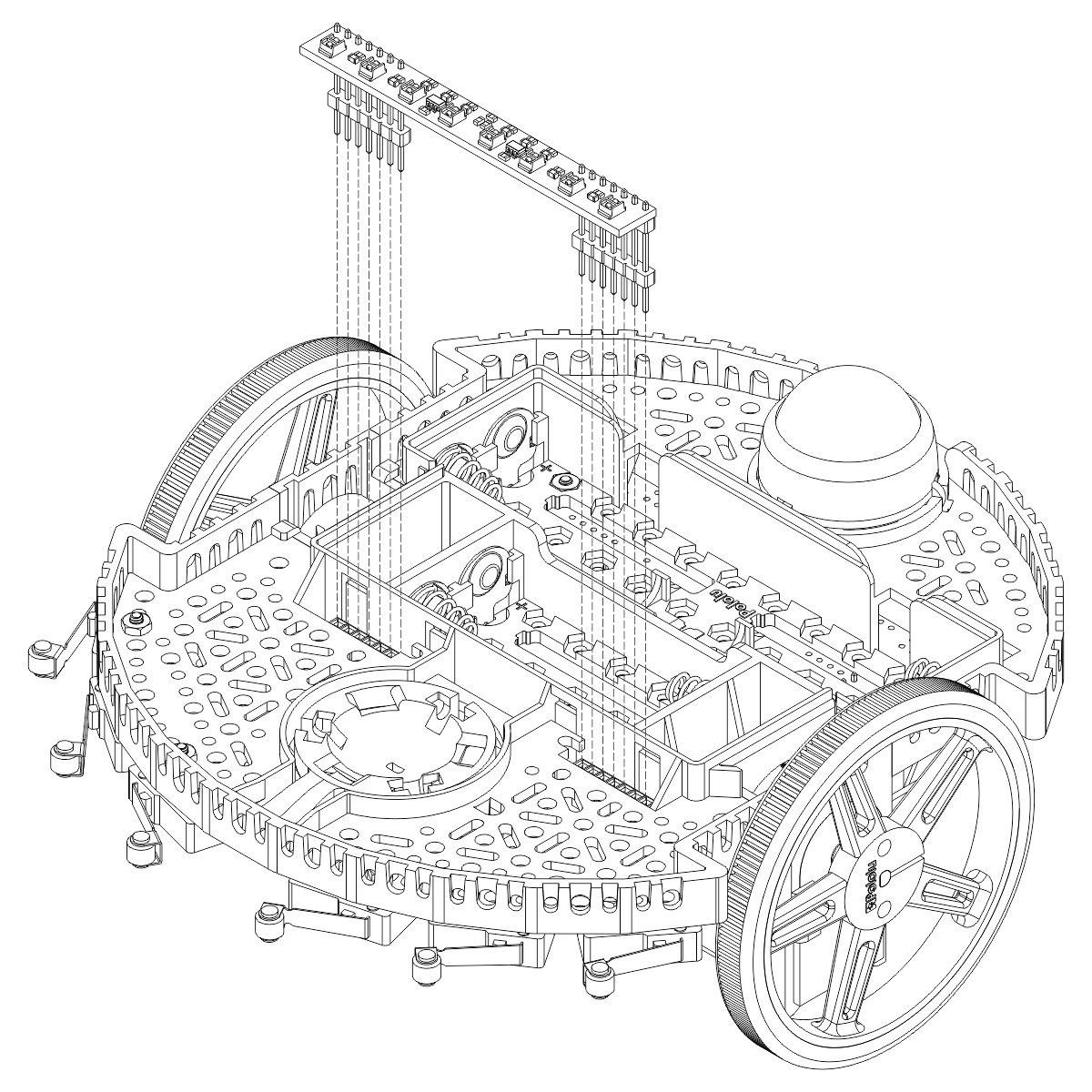
- Insert the right-angle male headers on the bumper switch boards into the right-angle female headers on the underside of the main board.
- Be sure that the headers are properly aligned and fully inserted.
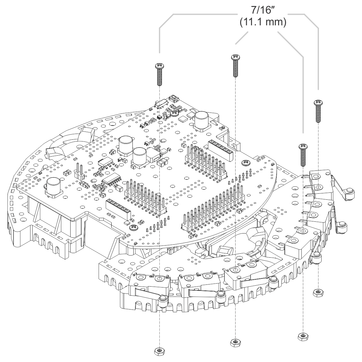
- Use four 7/16″ length, #2-56 screws (two in each bumper switch board) to secure the bumper switches to the chassis.
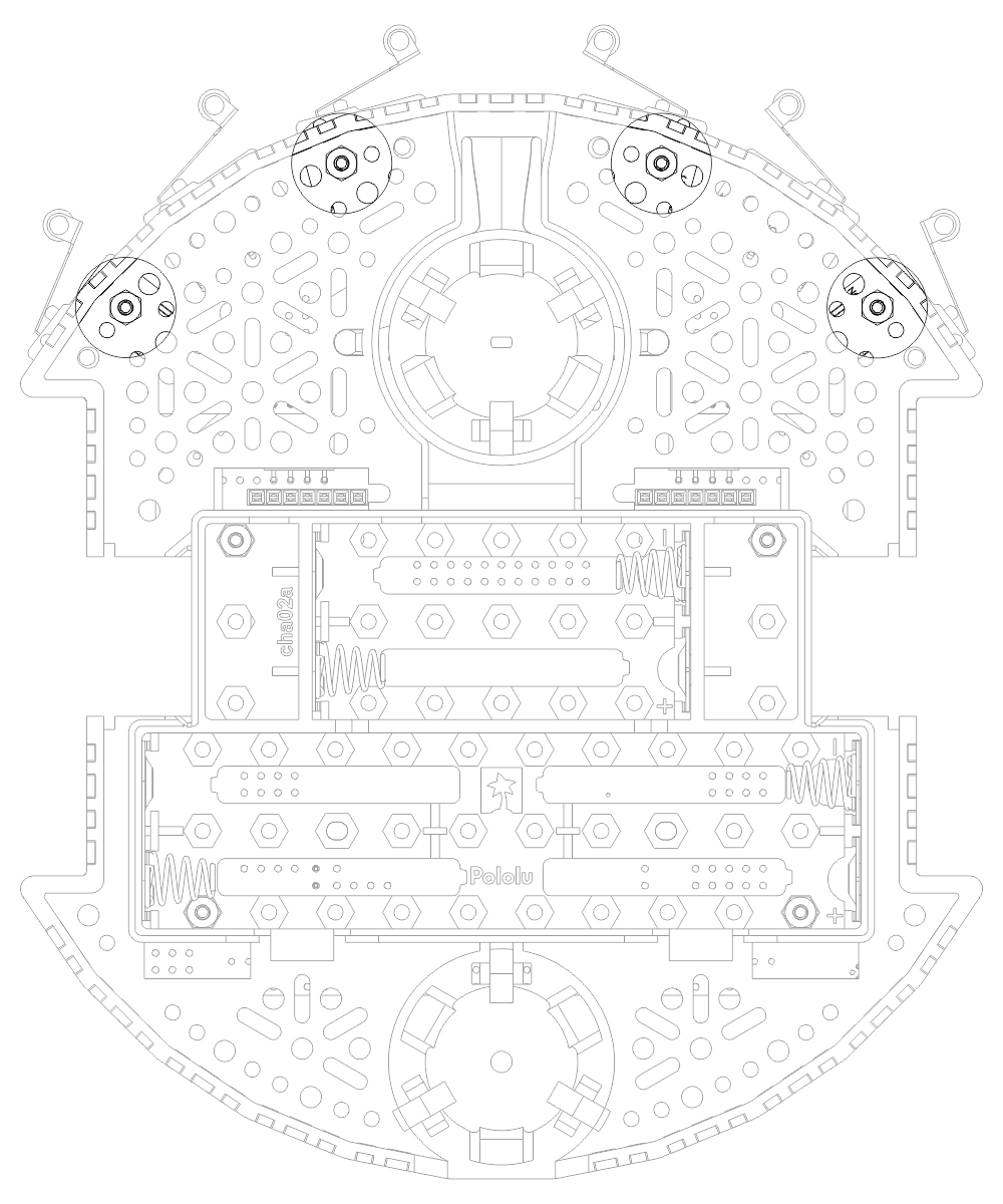
- Ensure the four #2-56 nuts are in the proper locations and securely fastened.
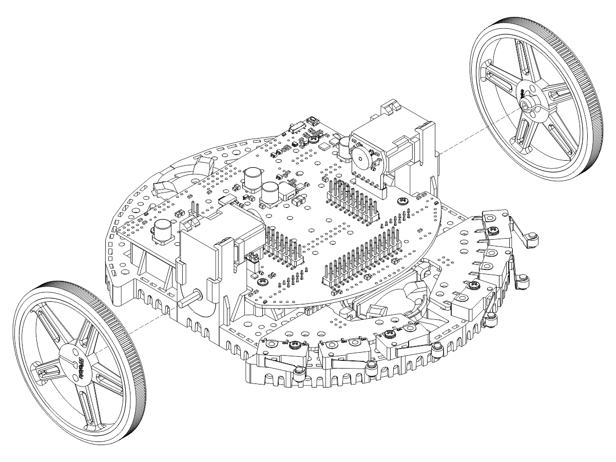
Motors with encoders
- Align the motor clips with the Romi chassis as indicated and press them firmly into the chassis until the bottom of the clips are even with the bottom of the chassis.
- You might hear multiple clicks when installing the motor clips; the motor clips should be flush with the bottom of the Romi chassis when they are properly installed. If they are not inserted all the way, the clip release will interfere with installing the motor.
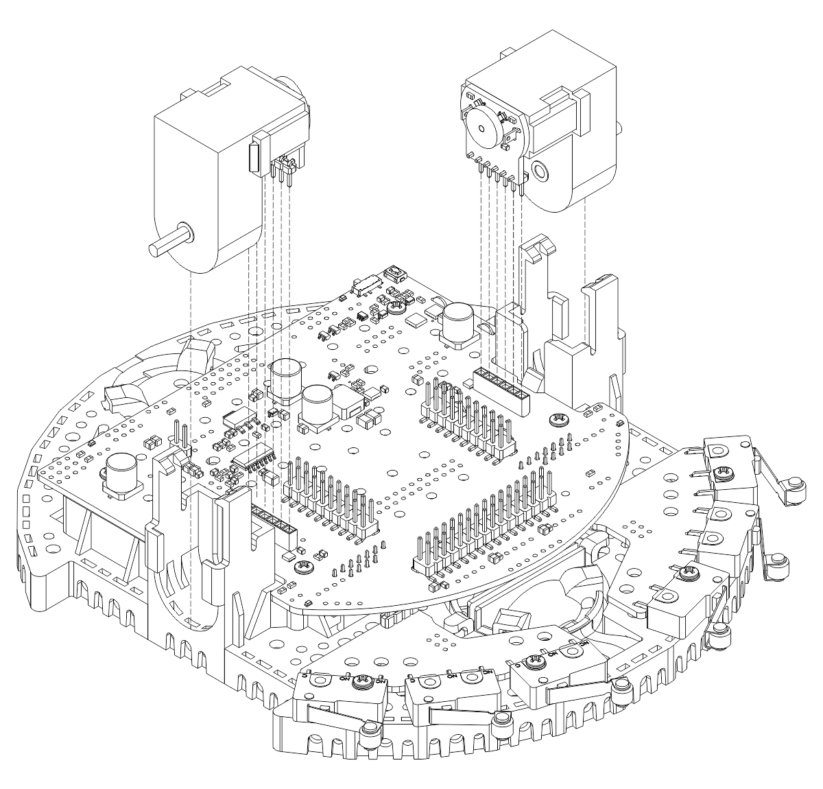
- Align the Mini Plastic Gearmotors and press them down into the motor clips until they snap into place. Note that the motor blocks the clip release, so if you need to remove a motor bracket later, you will first need to remove the motor.
- Ensure that the right-angle male headers on the encoder boards are aligned correctly and fully inserted into the female headers on the main board.
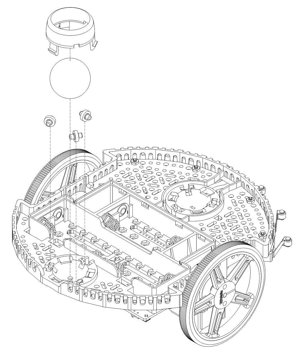
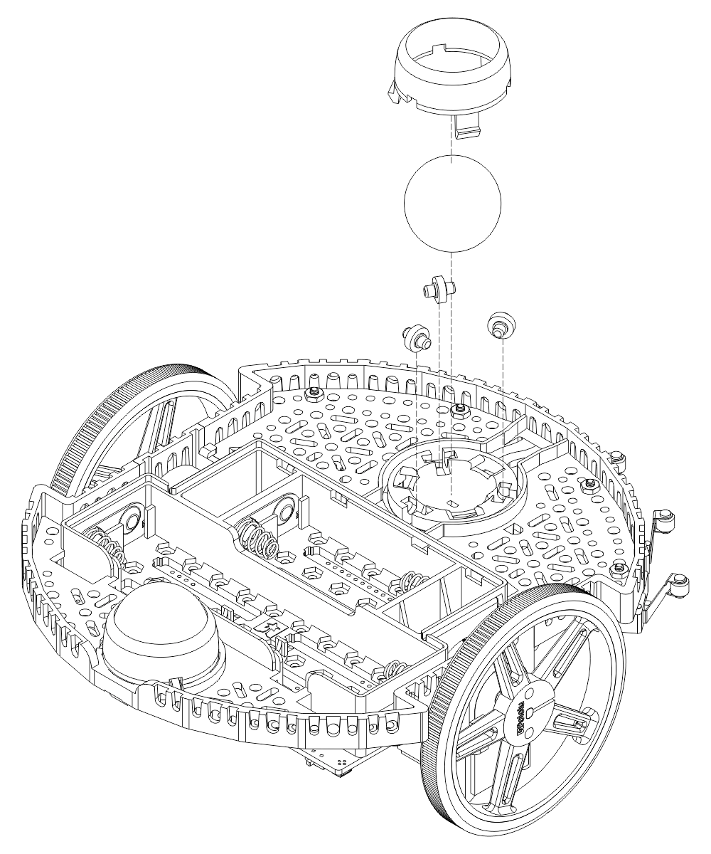
Wheels and ball caster(s)
- Press the wheels onto the output shafts of the motors until the motor shaft is flush with the outer face of the wheel. One way to do this is to set the wheel on a flat surface and line the chassis up with it so that the flat part of the motor’s D-shaft lines up correctly with the wheel. Then, lower the chassis, pressing the motor shaft into the wheel until it contacts the surface.
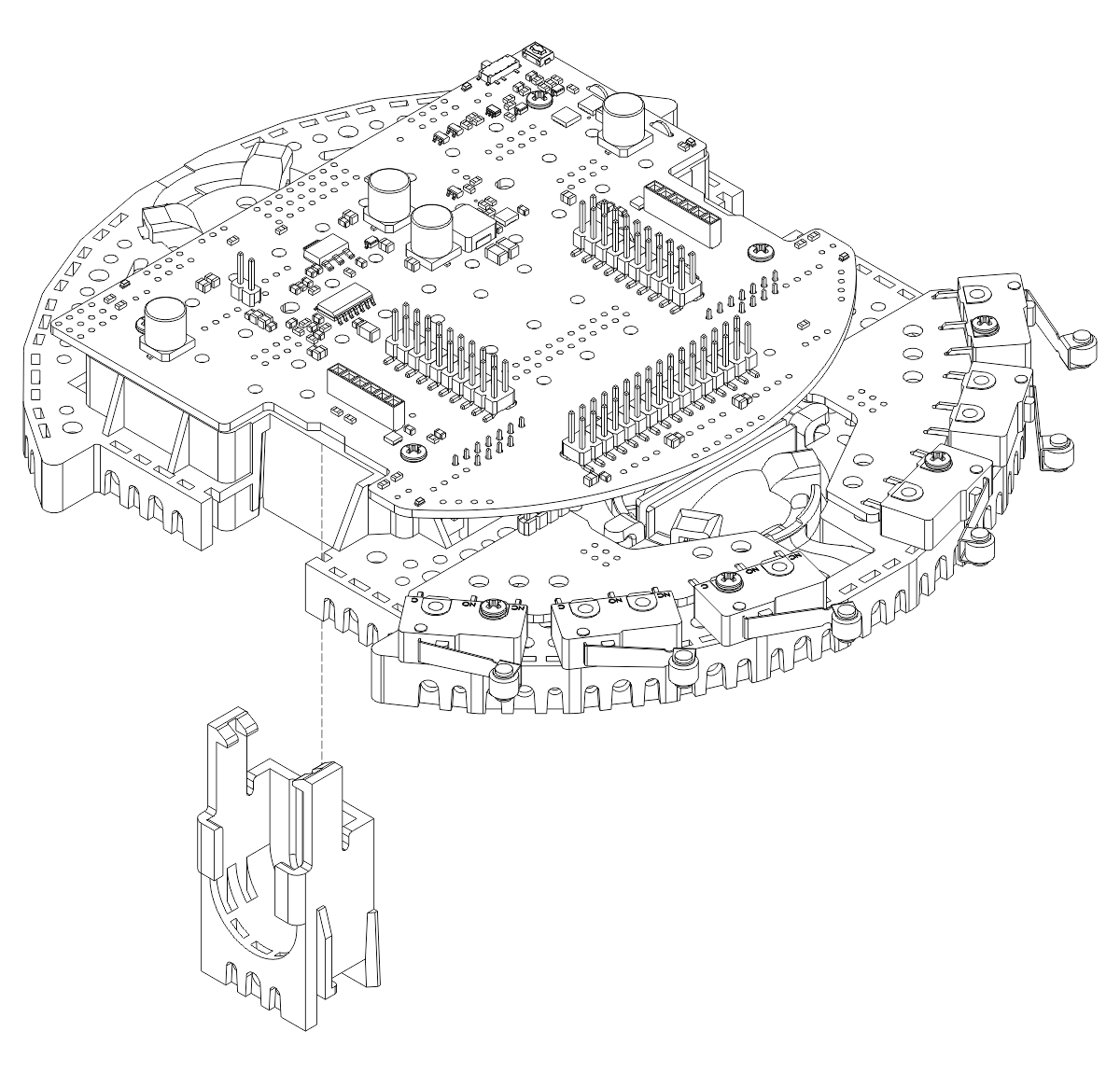
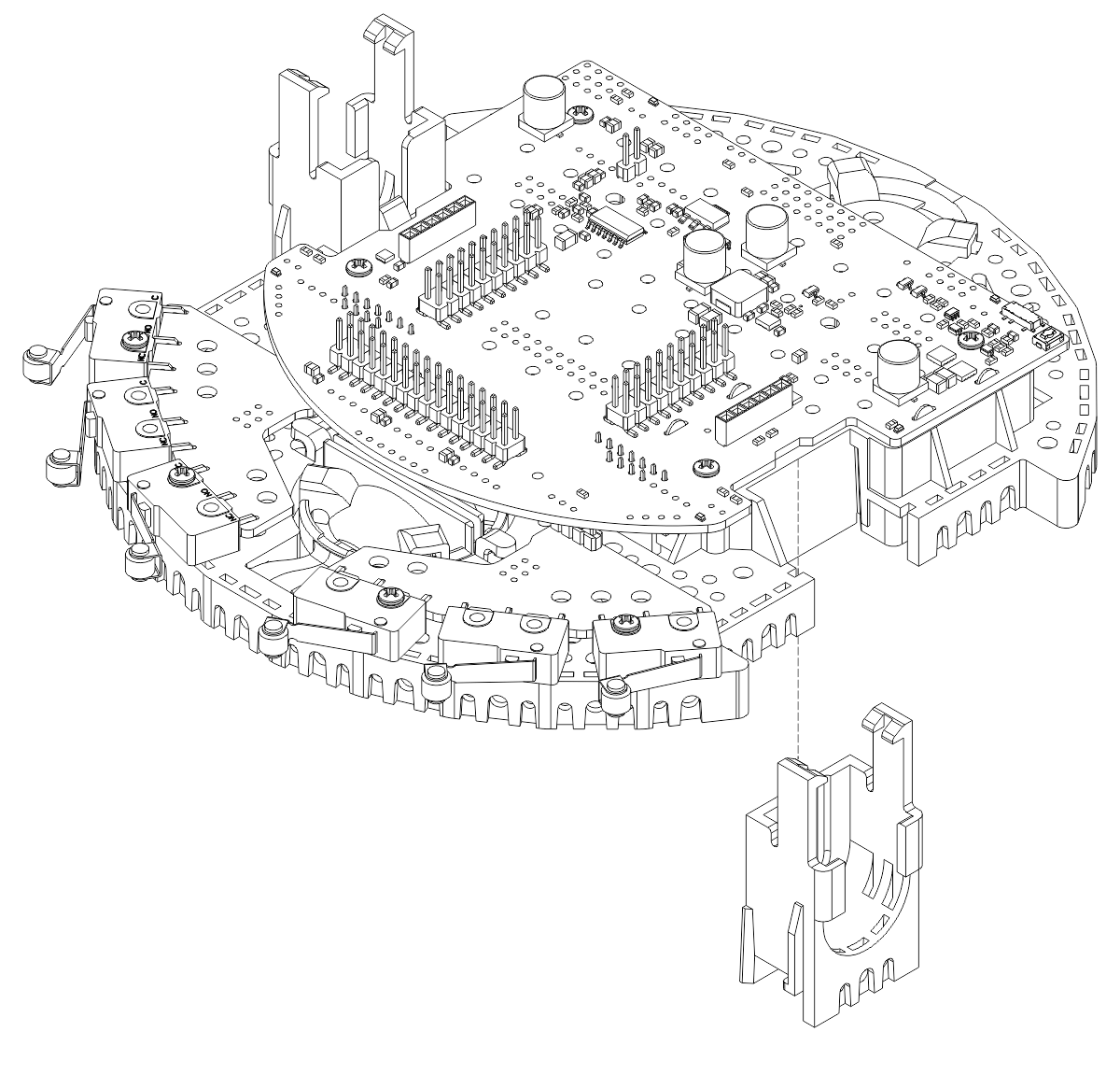
- Flip the Romi chassis upside down and place the three rollers for the rear ball caster into the cutouts in the chassis.
- Place the 1″ plastic ball on top of the three rollers.
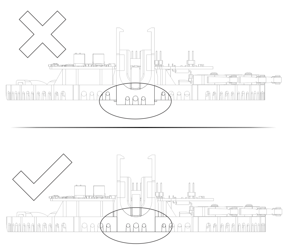
- Push the ball caster retention clip over the ball and into the chassis so the three legs snap into their respective holes.
- Optional: If you are using the optional second ball caster in the front of the robot, repeat the steps above for the front ball caster socket.
Line sensor and batteries
- With the Romi chassis still upside down, plug the 8-Channel QTRX line sensor array into the matching female headers on the bottom of the TI-RSLK MAX Chassis Board.
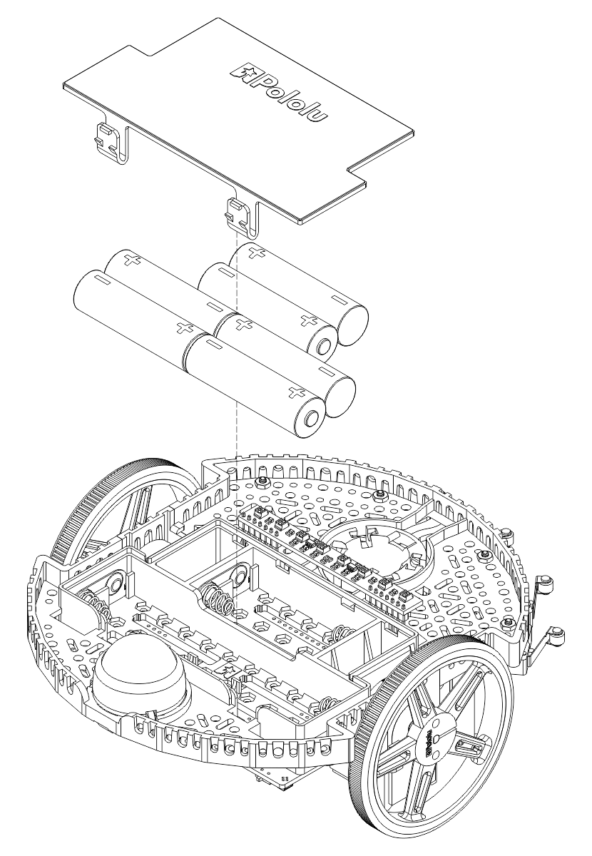
- Install six new or freshly charged AA batteries in the battery compartment. (We recommend using rechargeable AA NiMH cells.) Note that the correct orientation for the batteries is indicated by the battery-shaped cutouts in the Romi chassis as well as the + and – indicators in the chassis itself.
The assembly is now complete and ready for a TI MSP432 LaunchPad with the corresponding headers soldered to it.
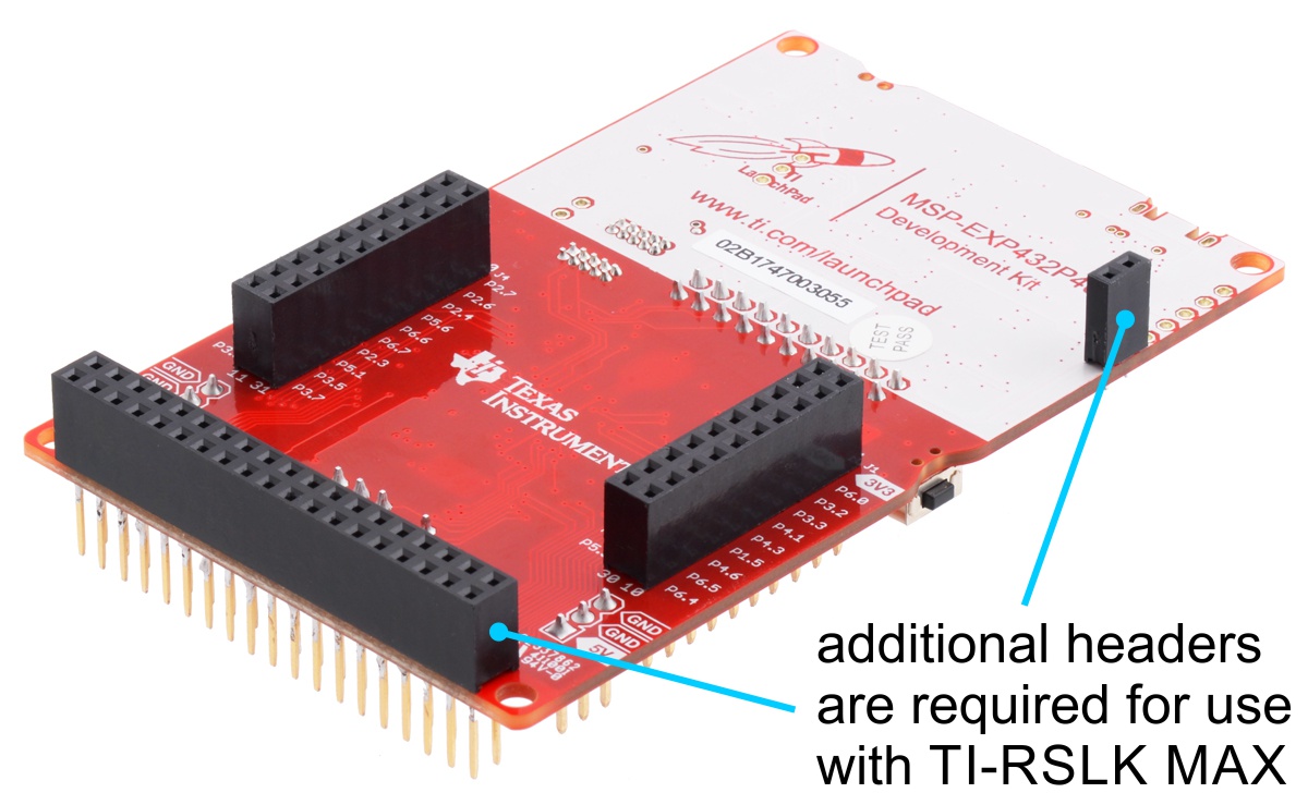
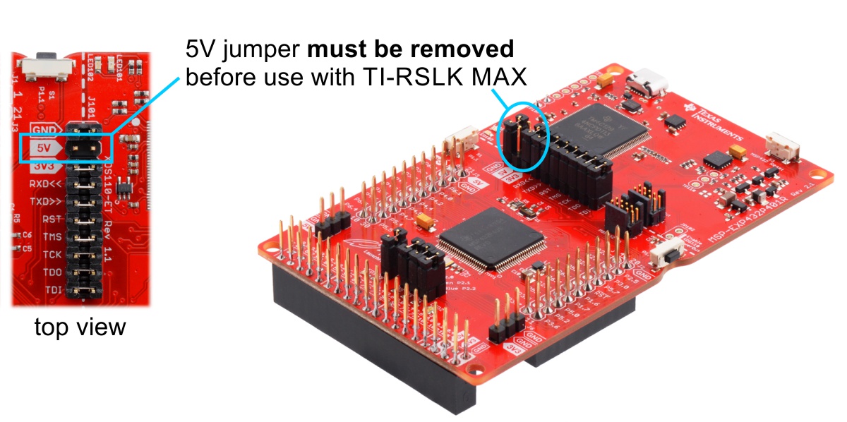
Note: This kit does not include a TI MSP432P401R LaunchPad, which is required to complete the TI-RSLK MAX robot. The LaunchPad must be specially assembled with a 2×19 stackable female header and a 1×2 female header so that it can plug into the Chassis Board, and the LauchPad’s 5V jumper must be removed prior to use with TI-RSLK MAX in order to avoid shorting different power rails and potentially damaging the Chassis Board. A properly assembled LaunchPad is included with the complete TI-RSLK MAX kit from Texas Instruments, and we also have them available separately.
Adding the included 400-point breadboard with mounting holes
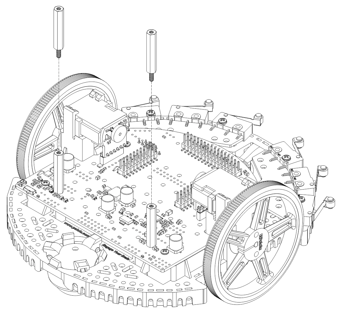
- Install a pair of 1" aluminum standoffs to the rear of the chassis as shown:
- Optional You can install a second pair of 1" aluminum standoffs to extend the height for the breadboard.
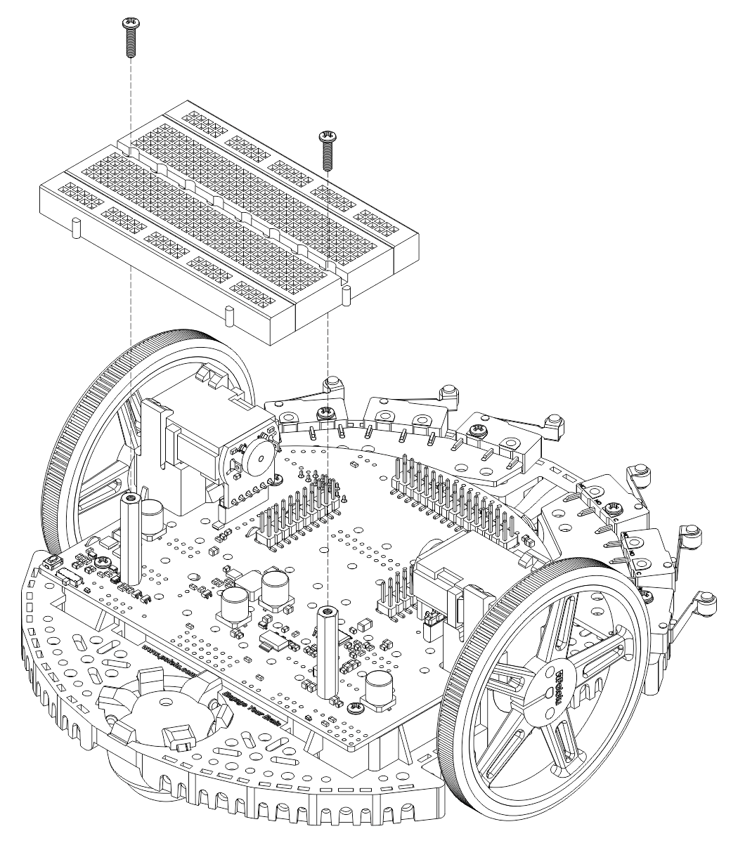
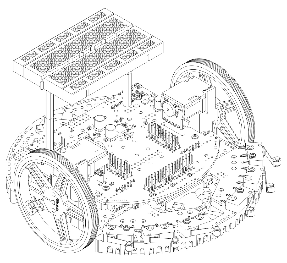
- Use two 3/8″ length, #2-56 screws to secure the breadboard on the aluminum standoffs.
- Your breadboard add-on is now complete!