TI Robotics System Learning Kit MAX (TI-RSLK MAX) Parts and Accessories »
Right Bumper Switch Assembly for Romi/TI-RSLK MAX (Through-Hole Pins Soldered)

This bump sensor module is designed specifically for use with Romi or TI-RSLK MAX robots based on the TI-RSLK Chassis Board v1.0, and it is included as part of the Pololu Chassis Kit for TI-RSLK MAX. It features three snap-action switches with roller levers and positions them along the right front edge of the Romi chassis, allowing the robot to determine where it has encountered an obstacle based on which switches get depressed. This module ships with the switches and right-angle header pins soldered, so no soldering is required to use it, and it is intended to be paired on the chassis with the Left Bumper Switch Assembly. A kit version is also available.
 Compare all products in TI Robotics System Learning Kit MAX (TI-RSLK MAX) Parts and Accessories.
| Description | Specs (3) | Pictures (11) | Resources (4) | FAQs (0) | On the blog (0) | Distributors (2) |
|---|
Overview
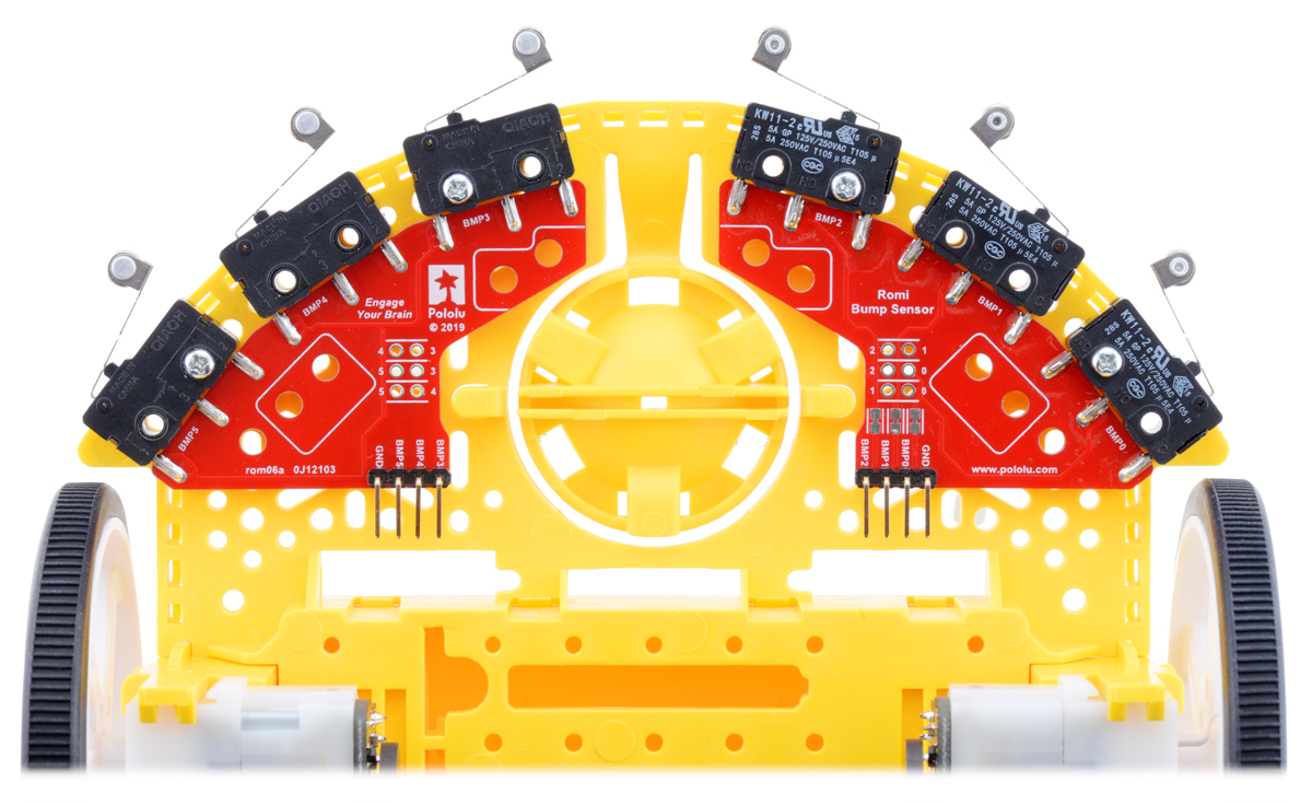 |
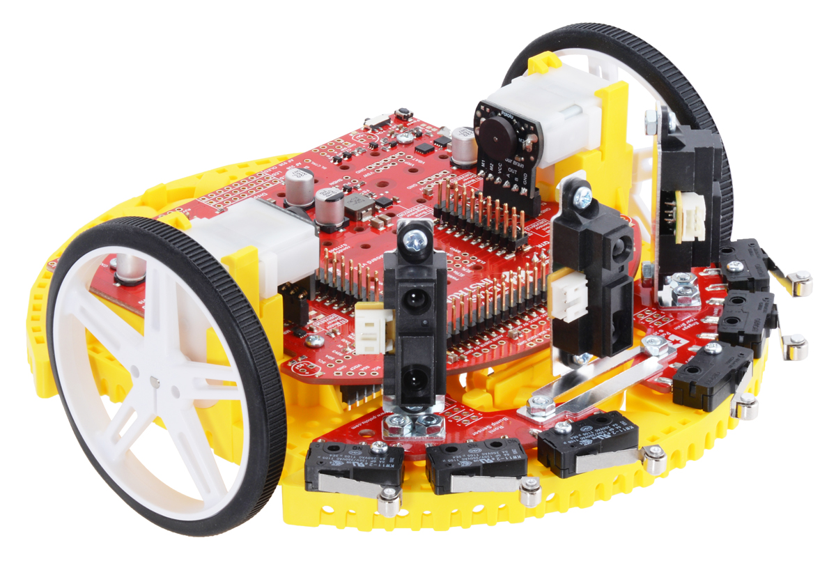
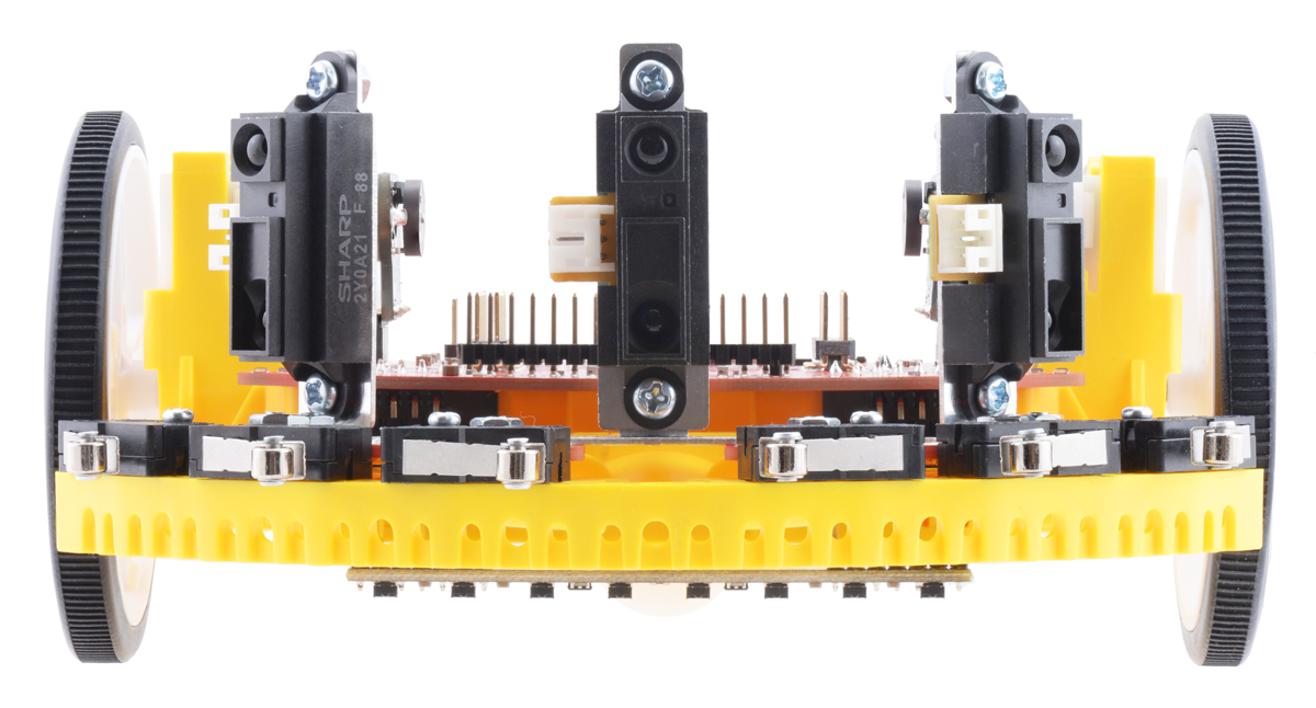
Left and right bumper switch assemblies mounted on a Romi chassis. |
|---|
These bump sensor modules for Romi or TI-RSLK MAX robots can be used to mount total of six snap-action switches with roller levers along the front half of the Romi chassis, enabling the robot to determine where it has encountered an obstacle based on which switches get depressed. The modules are intended to be used in pairs, with one mounted on the left front edge of the robot and another mounted on the right front edge. Three different assembly options are available:
- Fully assembled left bumper module
- Fully assembled right bumper module
- Bumper switch kit (this can be assembled for right or left side)
All three versions use the same PCB, with the side of the PCB facing up determining if it works on the left side or the right side. Once header pins are soldered in, that locks in the handedness of the module, which is why the assembled versions are predesignated left and right while the kit version can be assembled for either side.
The right-angle pins included with the module have custom dimensions designed specifically for use with corresponding female headers on the TI-RSLK Chassis Board v1.0, but they still have a 0.1″ pitch that is compatible with standard 0.1″ female headers, jumper wires, and connectors.
Details for item #3674
|
|

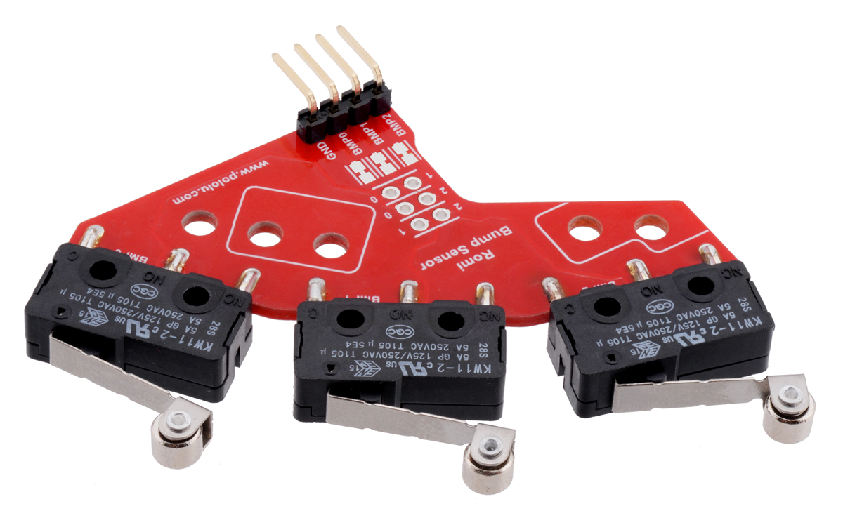
This bumper switch module version is fully assembled for use on the right front side of the Romi chassis, and it is intended to be paired with a Left Bumper Switch Assembly. No soldering is required to use it. A kit version is also available.
Using the module
|
|

Each of the module’s three BMPx outputs connect to the normally open (NO) pin of the correspond snap-action switch, so pull-up resistors should be used to give each pin a default high state (or the outputs should be connected to digital inputs with their internal pull-ups enabled). When the switch is depressed, the corresponding output is driven low.
Customizing the outputs
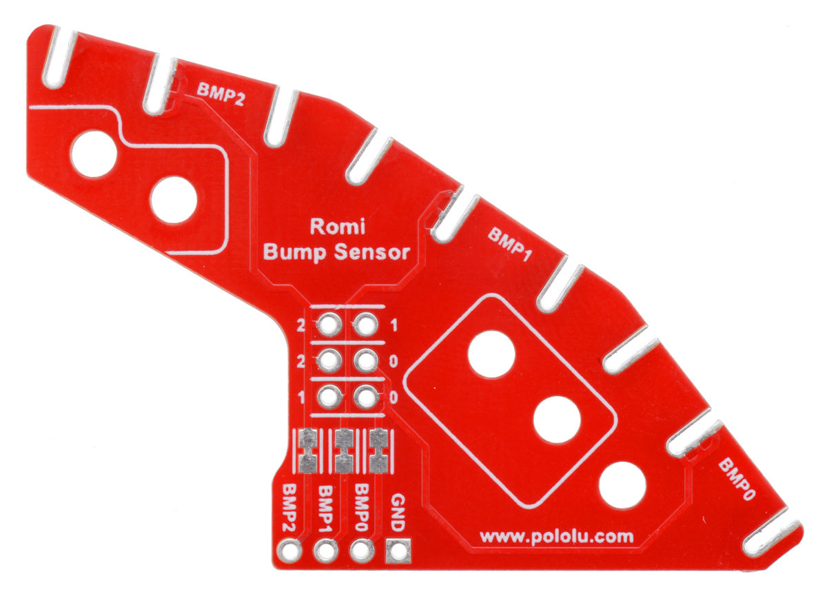
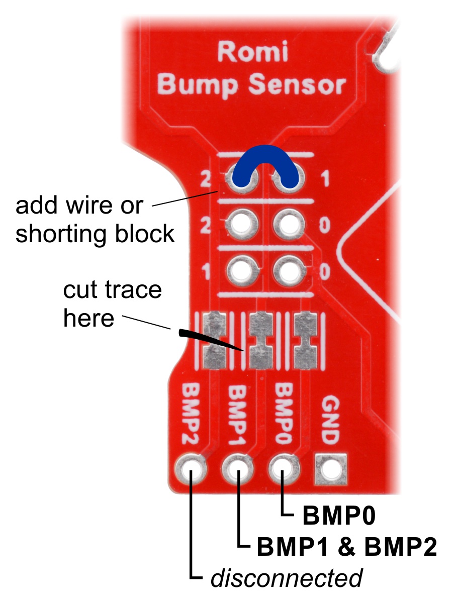
For applications where available I/O lines are limited and it is not important to detect which specific switch was closed, multiple switches can be connected to a single output using pairs of through-holes on the PCB. This makes it possible reduce the module to a pair of signals (with one combining the outputs of two different switches), or even to a single signal that indicates if any of the three switches has been triggered. The board also features designated places where traces can be cut with a knife to disconnect outputs from their corresponding switches, enabling any I/O lines connected to those outputs to be used for other things (those designated cutting points are between surface-mount jumpers that can later be bridged with solder to restore the connection).
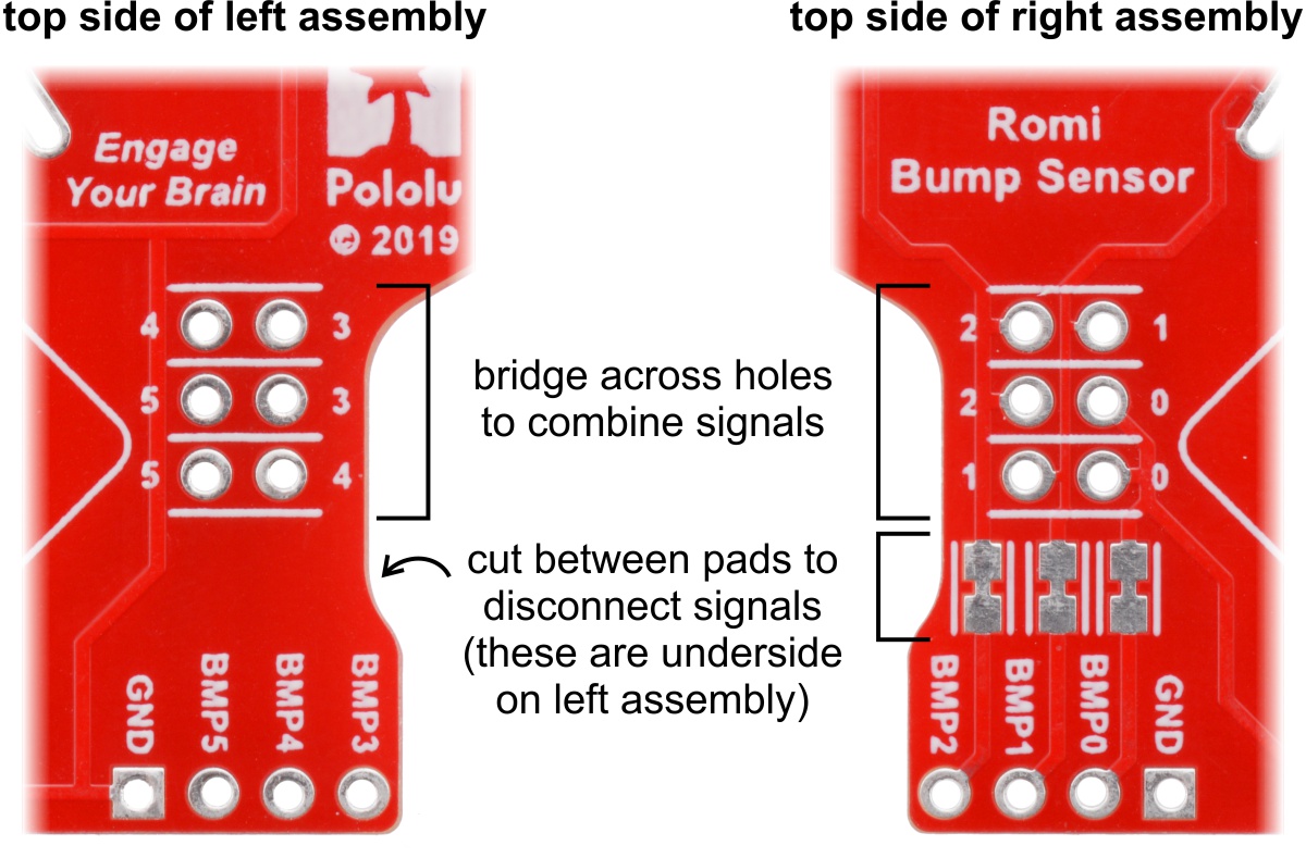 |
The following example shows how you could modify a unit to disconnect switch 2 from the BMP2 output and instead combine it with switch 1 on the BMP1 output. In this configuration, if either switch 1 or 2 is pressed, the BMP1 output will go low.
 |
Mounting to the Romi chassis
Two #2-56 7/16″ screws and nuts are included for mounting the bumper switch assembly to the Romi chassis.
If you are using these bumper switch assemblies with the TI-RSLK Chassis Board v1.0, the Chassis Board must be installed on the Romi chassis first. You can then slide each bumper switch assembly underneath the front edge of the Chassis Board until the right-angle male header plugs into the corresponding female header on the underside of the Chassis Board as shown below:
 |
Close-up view of Bumper Switch Assembly male header pins plugged into the female header on the Chassis Board. |
|---|
The bumper switch assemblies mount to the Romi chassis using the mounting holes in the roller switches highlighted in the diagram below:
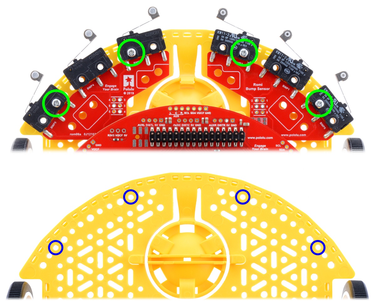 |
The left and right bumper switches assemblies use these mounting holes on the switches to mount to the Romi chassis. |
|---|
Using with the Sharp Distance Sensor Kit
These bumper switch assemblies work with the Sharp Distance Sensor Kit for Romi/TI-RSLK MAX, allowing you to add obstacle detection and ranging to your robot. The brackets for the Sharp distance sensors must be mounted to the bumper switch assemblies in the designated spots before the bumper switch assemblies are mounted to the Romi chassis. Assembly instructions can be found on the distance sensor kit’s product page.
|
|
Schematic diagram
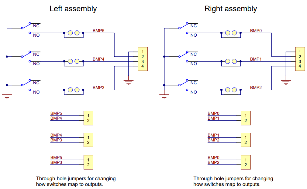 |
This diagram is also available as a downloadable pdf (91k pdf).
Related products


Home | Forum | Blog | Support | Ordering Information | Lists | Distributors | BIG Order Form | About | Contact
© 2001–2026 Pololu Corporation
