LEDs » Addressable RGB LEDs Based on the SK9822/APA102 » SK9822/APA102C-Based LED Panels »
Addressable RGB 8x32-LED Flexible Panel, 5V, 10mm Grid (SK9822)

This flexible LED panel contains 256 RGB LEDs arranged in an 8×32 grid. The LEDs can be individually addressed using an easy-to-control SPI interface, allowing you full control over the color of each RGB LED. The panel runs on 5 V and can be chained with additional SK9822 LEDs.

| Description | Specs (6) | Pictures (15) | Resources (6) | FAQs (0) | On the blog (1) | Distributors (0) |
|---|
Overview
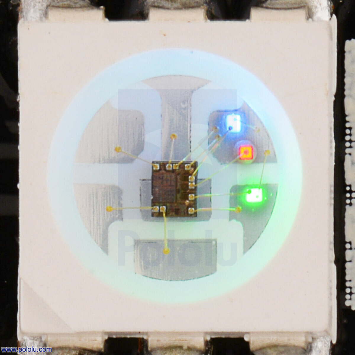 |
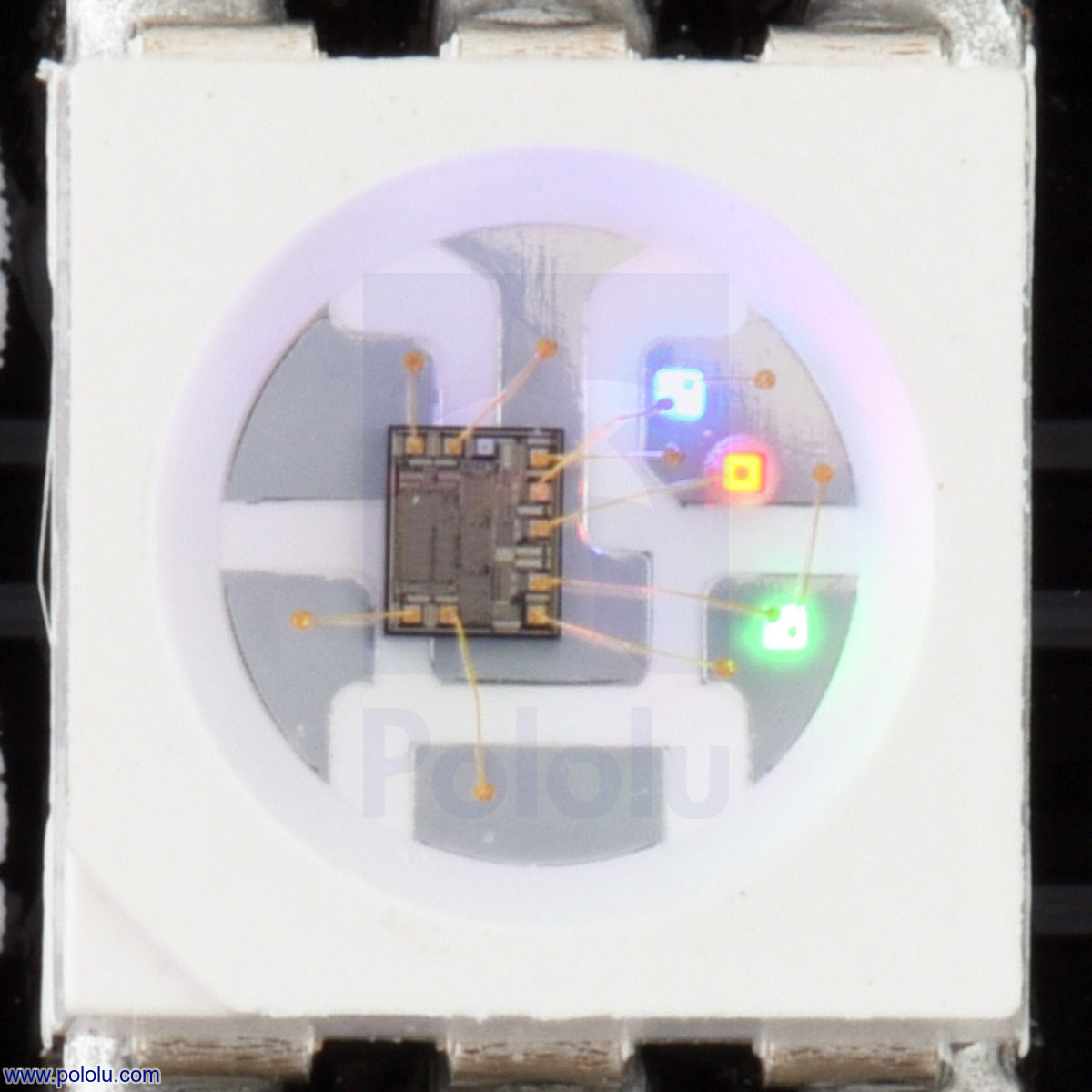
Close up of an SK9822, with the red, green, and blue LEDs on at a low brightness. |
|---|
These flexible RGB LED panels based on the SK9822 LED/driver IC are an easy way to add complex lighting effects to a project. Each SK9822 LED has an integrated driver that allows you to control the color and brightness of each LED. The SK9822 has constant current control, so voltage drops caused by the resistance in long power connections have little effect on the SK9822’s color and brightness as long as the voltage stays above 3.5 V. The panels can be chained together and can be chained to other SK9822-based products such as our SK9822-Based LED Strips.
These SK9822-based LED panels work as a drop-in replacement for our older APA102C-based panels in many applications. However, due to color differences, we do not recommend using the SK9822 and APA102C together in the same project. Also, due to a slight difference in the protocol, you might have to update your code to handle the SK9822. See below for a more detailed comparison of the SK9822 and APA102C.
We offer SK9822 LED panels in three different sizes:
We also have these LEDs available in strips.
Warning: These LED panels can draw a lot of current and overheat if they are operated at full brightness, so we recommend limiting the brightness. See the “Current draw” section below for more information.
While these LED panels are flexible, they should not be bent too sharply, and they are not recommended for use in applications where they will be subjected to repeated flexing.
Details for item #3094
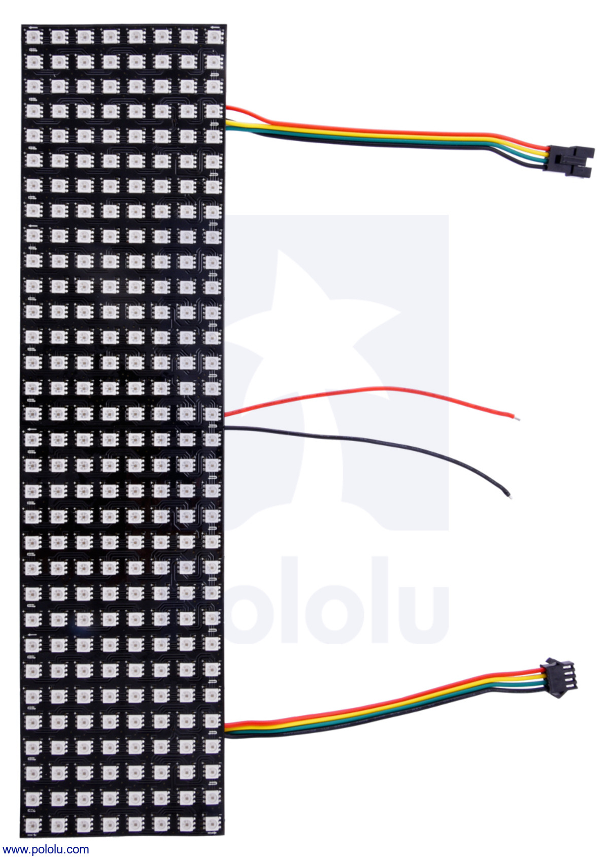
This flexible LED matrix contains 256 RGB LEDs arranged in an 8×32 grid.
|
|
Features and specifications
- Individually addressable RGB LEDs
- 24-bit color control
- Additional 5-bit brightness control; 32 brightness steps per pixel
- SPI control interface
- 5 V operating voltage
- Color and brightness are mostly voltage-independent down to 3.5 V
- Each RGB LED draws approximately 50 mA with red, green, and blue at full brightness
- 1.0 cm spacing between LED centers
- Black panel color
- Power/data connectors for easy chaining, and additional power and ground wires for alternate power connections
- Example code available for Arduino
 |
Addressable RGB 8×32-LED Flexible Panel, 5V, 10mm Grid (APA102C or SK9822) showing an animated rainbow. |
|---|
Using the LED panel
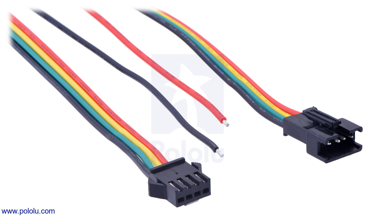 |
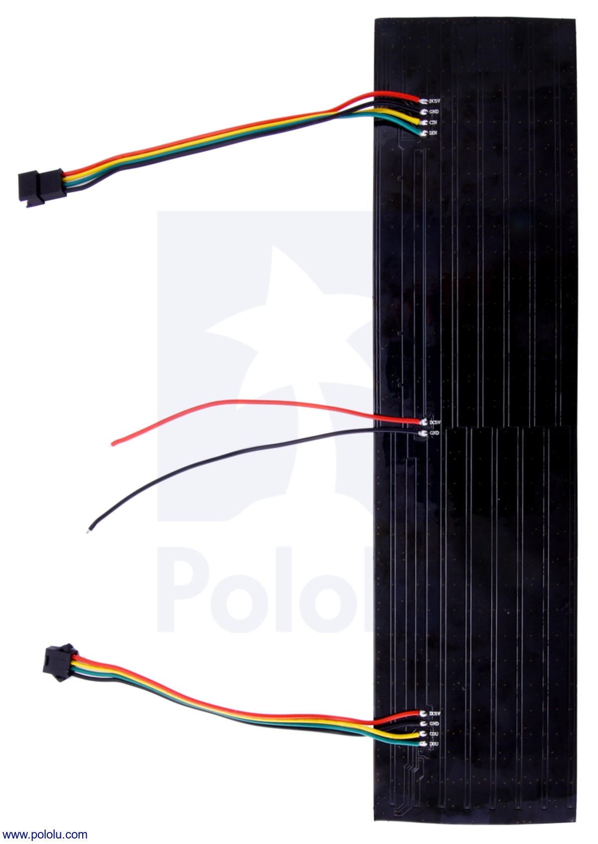
The connectors and power wires for our SK9822 and APA102C LED panels. From left to right: output connector, auxiliary power wires, input connector. |
|---|
Each LED panel has three connection points: the input connector, the auxiliary power wires, and the output connector. These can be seen in the adjacent picture.
The input connector has four male pins inside of a plastic connector shroud, each separated by about 0.1″. The black wire is ground, the green wire is the data signal input (DIN), the yellow wire is the clock signal input (CIN), and the red wire is the power line.
The auxiliary power wires consist of stripped black and red wires. The black wire is ground, and the red wire is the power line. This provides an alternate (and possibly more convenient) connection point for LED matrix power.
The output connector is designed to mate with the input connector of another SK9822 LED product to allow the panel to be chained to it. The black wire is ground, the green wire is the data output (DOU), the yellow wire is the clock output (COU), and the red wire is the power line.
All three black ground wires are electrically connected, and all three red power wires are electrically connected.
Connecting the LED panel
To control the LED panel from a microcontroller, three wires from the input connector should be connected to your microcontroller. The LED panel’s ground (black) should be connected to ground on the microcontroller, and the LED panel’s data input line (green) and clock input line (yellow) should each be connected to one of the microcontroller’s I/O lines. The male pins inside the input connector fit the female terminations on our premium jumper wires and wires with pre-crimped terminals. If you are connecting the LED panel to a breadboard or a typical Arduino with female headers, you would want to use male-female wires.
We generally recommend powering the LED panel using the auxiliary power wires. Our 5 V wall power adapters work well for powering these LED panels and a DC Barrel Jack to 2-Pin Terminal Block Adapter can help you make the connection between the adapter and the panel. However, you might need a wire stripper to strip off some more insulation from the power wires.
It is convenient that the power wires are duplicated on the input side because you can connect the auxiliary power wires to your 5 V power supply and then the power will be available on the data input connector and can be used to power the microcontroller that is controlling the LED panel. This means you can power the microcontroller and LED panel from a single supply without having to make branching power connections.
Current draw
Each SK9822 LED draws approximately 50 mA with red, green, and blue at full brightness, and has a maximum operating temperature of 80°C. These LED panels can draw a significant amount of current and overheat if they are operated at their full brightness, so we recommend limiting the brightness of the colors you send to the panel. Alternatively, you can take other measures to reduce the power drawn by the LED panel. For example, limiting the number of LEDs that are on at the same time and limiting how long the LEDs are on can help reduce the power drawn and keep the panel from overheating.
The SK9822 has built-in constant current control. For any given color command, the SK6812’s actual color and brightness are largely independent of its supply voltage as long as the voltage is between 3.5 V and 5 V. This means that voltage drops caused by the resistance in long power connections are less likely to affect the color or brightness of the light emitted.
Color
The hue of the light emitted by the SK9822 becomes less red and more green as the 5-bit brightness value is lowered. Also, the SK9822 has some unit-to-unit variation in the brightness of its red channel which can be noticed when the 5-bit brightness value is low but is usually hard to see when the 5-bit brightness value is high.
LED panel layout
The LEDs in the panel are connected in a “serpentine” or “boustrophedon” layout, meaning that the direction of the data signals in each row alternates. The signals in each row go in the direction that is the opposite of the row before it. The top side of the LED panel has white arrows to indicate which direction the signals propagate.
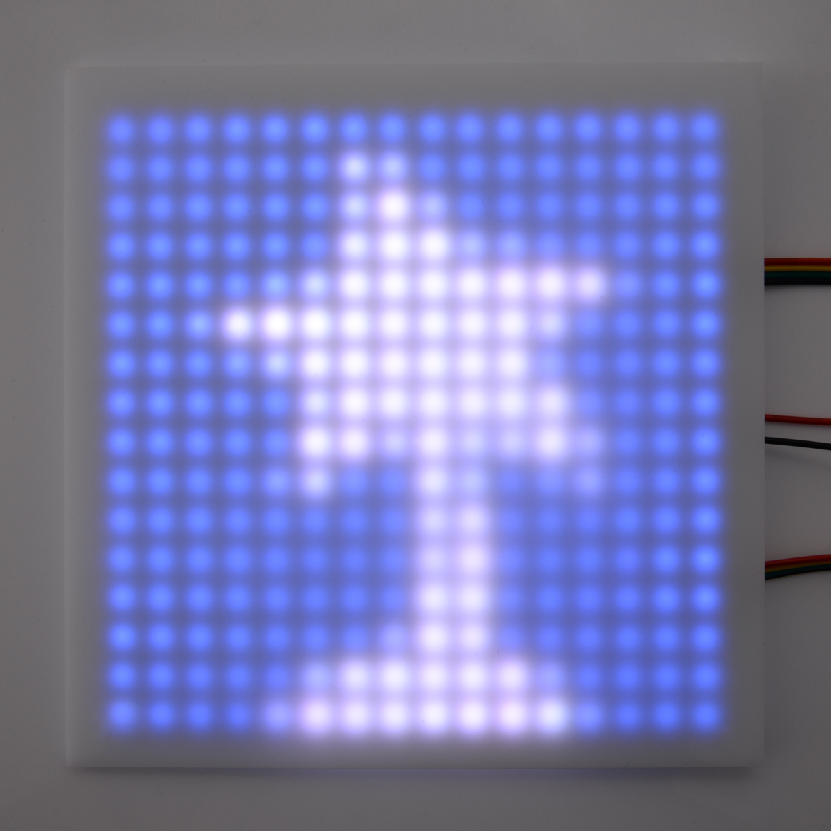 |
An addressable RGB 16×16-LED panel with a plastic diffuser (not included) showing the Pololu logo. |
|---|
Making a custom cable
If you do not want to use our premium jumper wires to connect to the LED panel’s input, it is possible to make a custom cable.
One option for making a custom cable is to cut off the unused output connector on the last LED panel in your chain. This can then be plugged into the input connector of the first LED panel. The wires on the output and input connectors are 20 AWG, which is too thick to easily use with our crimp pins and housings, but you could solder the wires to header pins.
Alternatively, you can get your own JST SM connectors and make a custom cable using those. The parts you would need to get are the SMP-04V-BC and the SHF-001T-0.8BS, which are described in the SM Connector datasheet from JST. These can be purchased from several places, including Heilind. You will also need some 22–28 AWG stranded wire and a wire stripper. We do not know of a great way to crimp wires onto the JST crimp pins, but we were able to successfully do it using our narrower crimping tool and pliers. (With the wider crimping tool, it is hard to avoid crimping parts of the pin that should not be crimped.) Before crimping, use pliers to bend the outer set of tabs a little bit so that they can hold on to the insulation of the wire. This makes it easier to position the crimp pin and the wire. Next, you should be able to follow the instructions on the crimping tool product page to crimp the wire. After that, you will probably need to squeeze the crimp pin with pliers to get it to fit into the JST plug housing. On the other end of the cable you could make a custom connector using our crimp pins and crimp connector housings, which will allow you to plug it directly into a breadboard or 0.1″ header pins.
Protocol
These LED panels are controlled through an SPI protocol on the data and clock input lines. The protocol is documented in the SK9822 datasheet (476k pdf), but we describe it below with some modifications that we have found to work better.
The default, idle state of the clock signal line is low, and the data signal is read on each rising edge of the clock. To update the LED colors, you need to toggle the clock line while driving the data line with the value of each bit to send; this can be done through software (bit-banging), or it can be handled by a hardware SPI peripheral in a microcontroller. There is no minimum clock frequency, although using a lower frequency means that it will take longer to update the entire sequence of LEDs (especially when controlling a large number of LEDs), so you will probably want to use the fastest practical clock speed to get the best update rate.
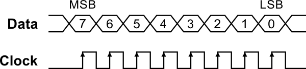 |
Control signal timing diagram for the SK9822 and APA102C. |
|---|
The data for each LED is encoded as a sequence of 32 bits (4 bytes) called an LED frame. The first 3 bits of the LED frame should be ‘1’. The next 5 bits are a “global” brightness value (0–31) that is applied to all three color channels. The remaining 24 bits are the color values, in BGR (blue-green-red) order. Each color value uses 8 bits (0–255). The most significant bit of each value is transmitted first. The first LED frame transmitted applies to the LED in the corner closest to the data input connector, while the second color transmitted applies to the next LED in the panel as indicated by the arrows, and so on.
To update all the LEDs in the panel, you should send a “start frame” of 32 ‘0’ bits, then a 32-bit “LED frame” for each LED, and finally an “end frame”.
The SK9822 datasheet recommends that the end frame be composed of 32 ‘1’ bits, but we have found this does not work reliably in certain situations and can sometimes lead to glitches. This can be avoided by using an end frame that consists of at least ``(n – 1)`` extra clock edges, where ``n`` is the number of LEDs, with ‘0’ on the data line. It is often easiest to round up to a multiple of 16 clock edges so that you are counting bytes instead (there are 2 clock edges in a bit and 8 bits in a byte); you would therefore send ``((n – 1) // 16)`` bytes (rounded up to the next whole number). For a more detailed explanation, see the comments in the source code of our Arduino library, discussed below.
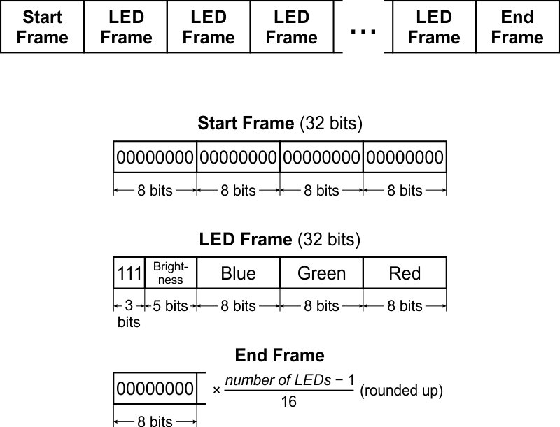 |
Data format for the SK9822 and APA102C. |
|---|
Each RGB LED receives data on its data input line and passes data on to the next LED using its data output line. The update rate is generally limited only by the speed of the controller; our Arduino library below can update 60 LEDs in about 1.40 milliseconds, so it is possible to update 700 LEDs at 60 Hz. However, constant updates are not necessary; the LED strip can hold its state indefinitely as long as power remains connected.
Note: The minimum logic high threshold for the data and clock signals is not specified in the SK9822 datasheet, so you should consider using level shifters if you want to control these strips from 3.3 V systems. In our tests, we were able to control the LEDs directly with 3.3 V signals, but that is not guaranteed to always work.
Sample code
To help you get started quickly, we provide an APA102 Arduino library. Our APA102 library supports both the SK9822 and the APA102 (an LED/driver IC that has a nearly identical interface). The library also works with our Arduino-compatible A-Star modules.
Additionally, the DotStar Arduino library and Raspberry Pi Python module from Adafruit should work with these strips since the DotStars are based on similar LEDs. The FastLED Arduino library is another option that focuses on performance and provides advanced functionality like color correction.
Since the SK9822 is similar to the APA102, most code written for the APA102 should work with the SK9822.
Comparison with APA102C LED Panels
The SK9822 is very similar to the APA102C used in some of our older LED products, and can be used as a drop-in replacement in almost any application. LED products based on the SK9822 and APA102C can be chained together.
The SK9822 has voltage-independent brightness over a wide voltage range, as described in the “Current draw” section, which means that the colors of the LEDs should not be affected by a drop in the supply voltage as much as they are on the APA102C.
The colors generated by the SK9822 look different from the colors generated by the APA102C. In particular, the SK9822’s red channel is relatively less bright, which makes it have a blue-green tint when compared to the APA102C. While the APA102C’s brightness register allows you to control the brightness of each LED independently of its color, we have noticed that the colors from the SK9822 become less red and more green as the 5-bit brightness value is lowered. Also, the SK9822 has some unit-to-unit variation in the brightness of its red channel, which can be noticed when the 5-bit brightness value is low but is usually hard to see when the 5-bit brightness value is high.
The SK9822 can be distinguished from the APA102C by visual inspection. The pictures below show what each IC looks like:
|
|
Related products


Related categories


Home | Forum | Blog | Support | Ordering Information | Lists | Distributors | BIG Order Form | About | Contact
© 2001–2026 Pololu Corporation
