Sensors » Proximity Sensors and Range Finders » Carriers for ST Time-of-Flight (ToF) Distance Sensors »
VL6180X Time-of-Flight Distance Sensor Carrier with Voltage Regulator, 60cm max

This sensor is a carrier/breakout board for ST’s VL6180X proximity and ambient light sensor, which measures the range to a target object up to 20 cm away (or 60 cm with reduced resolution). The VL6180X uses time-of-flight measurements of infrared pulses for ranging, allowing it to give accurate results independent of the target’s color and surface. Distance and ambient light level measurements can be read through a digital I²C interface. The board has a 2.8 V linear regulator and integrated level-shifters that allow it to work over an input voltage range of 2.6 V to 5.5 V, and the 0.1″ pin spacing makes it easy to use with standard solderless breadboards and 0.1″ perfboards.
 Compare all products in Carriers for ST Time-of-Flight (ToF) Distance Sensors or Environmental Sensors.
| Description | Specs (10) | Pictures (9) | Resources (10) | FAQs (0) | On the blog (4) | Distributors (74) |
|---|
 |
Overview
The VL6180X from ST Microelectronics is a sensor that combines proximity ranging and ambient light level measurement capabilities into a single package. This board is a carrier for the VL6180X, so we recommend careful reading of the VL6180X datasheet (2MB pdf) before using this product.
Unlike simpler optical sensors that use the intensity of reflected light to detect objects, the VL6180 uses ST’s FlightSense technology to precisely measure how long it takes for emitted pulses of infrared laser light to reach the nearest object and be reflected back to a detector, making it essentially a short-range lidar sensor. This time-of-flight (TOF) measurement enables it to accurately determine the absolute distance to a target with 1 mm resolution, without the object’s reflectance influencing the measurement. The sensor is rated to perform ranging measurements of up to 10 cm (4″), but it can often provide readings up to 20 cm (8″) with its default settings. Furthermore, the VL6180X can be configured to measure ranges of up to 60 cm (24″) at the cost of reduced resolution, although successful ranging at these longer distances will depend heavily on the target and environment. (For more information, see “Range scaling factor” below.)
The VL6180 also includes an ambient light sensor, or ALS, that can measure the intensity of light with which it is illuminated. Ranging and ambient light measurements are available through the sensor’s I²C (TWI) interface, which is also used to configure sensor settings, and two independently-programmable GPIO pins can be configured as interrupt outputs.
The VL6180X is a great IC, but its small, leadless, LGA package makes it difficult for the typical student or hobbyist to use. It also operates at voltages below 3 V, which can make interfacing difficult for microcontrollers operating at 3.3 V or 5 V. Our breakout board addresses these issues, making it easier to get started using the sensor, while keeping the overall size as small as possible.
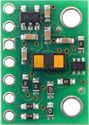
The carrier board includes a low-dropout linear voltage regulator that provides the 2.8 V required by the VL6180X, which allows the sensor to be powered from a 2.6 V to 5.5 V supply. The regulator output is available on the VDD pin and can supply around 100 mA to external devices. The breakout board also includes a circuit that shifts the I²C clock and data lines to the same logic voltage level as the supplied VIN, making it simple to interface the board with 3.3 V or 5 V systems, and the board’s 0.1″ pin spacing makes it easy to use with standard solderless breadboards and 0.1″ perfboards. The board ships fully populated with its SMD components, including the VL6180X, as shown in the product picture.
Alternative versions
 |
Comparison of the VL6180X, VL53L4CD, VL53L0X, VL53L1X, VL53L3CX, VL53L5CX, VL53L7CX, and VL53L8CX Time-of-Flight Distance Sensor Carriers. |
|---|
For other similar sensors with longer ranges, see the comparison section at the bottom of this page.
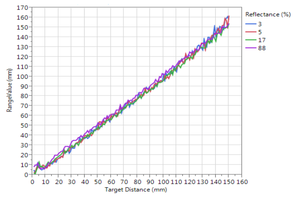 |
VL6180X datasheet graph of typical ranging performance. |
|---|
Specifications
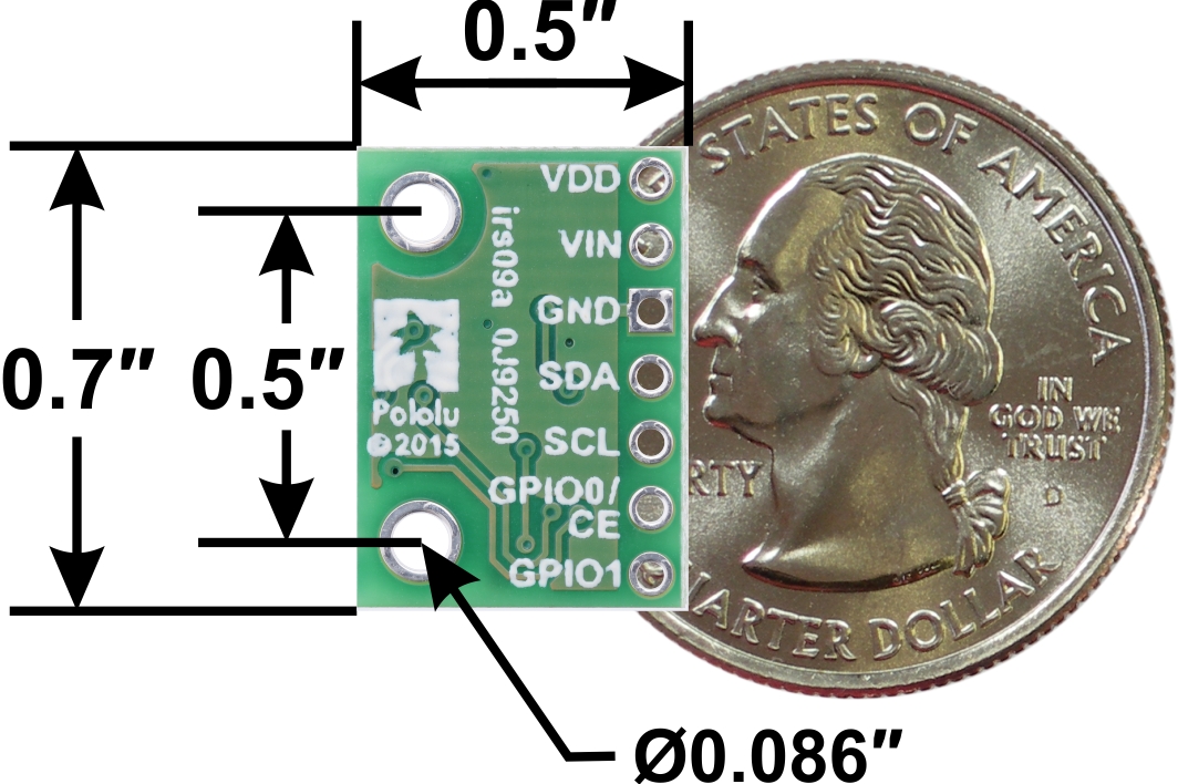
- Dimensions: 0.5″ × 0.7″ × 0.085″ (13 mm × 18 mm × 2 mm)
- Weight without header pins: 0.5 g (0.02 oz)
- Operating voltage: 2.6 V to 5.5 V
- Typical active-ranging supply current: 25 mA
- Varies with configuration, target, and environment; peak current can reach 40 mA
- Output format (I²C): 8-bit distance reading (in millimeters), 16-bit ambient light reading
- Distance measuring range: up to 10 cm (4″) specified; up to 60 cm (24″) possible with reduced resolution. See the graph at the right for typical ranging performance.
- Ranging beyond 10 cm is possible with certain target reflectances and ambient conditions but not guaranteed by specifications. By default, the sensor can report distances up to 20 cm, or it can be configured to measure up to 60 cm with reduced resolution.
- The datasheet does not specify a minimum range, but in our experience, the effective limit is about 1 cm.
Included components
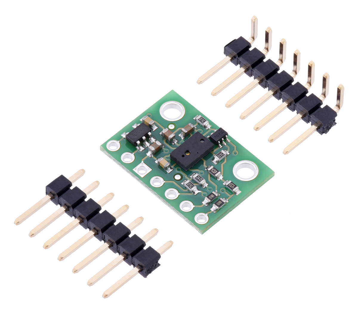
A 1×7 strip of 0.1″ header pins and a 1×7 strip of 0.1″ right-angle header pins are included, as shown in the picture below. You can solder the header strip of your choice to the board for use with custom cables or solderless breadboards, or you can solder wires directly to the board itself for more compact installations.
|
|
The board has two mounting holes spaced 0.5″ apart that work with #2 and M2 screws (not included).
Using the VL6180
Connections
 |
| Pin | Description |
|---|---|
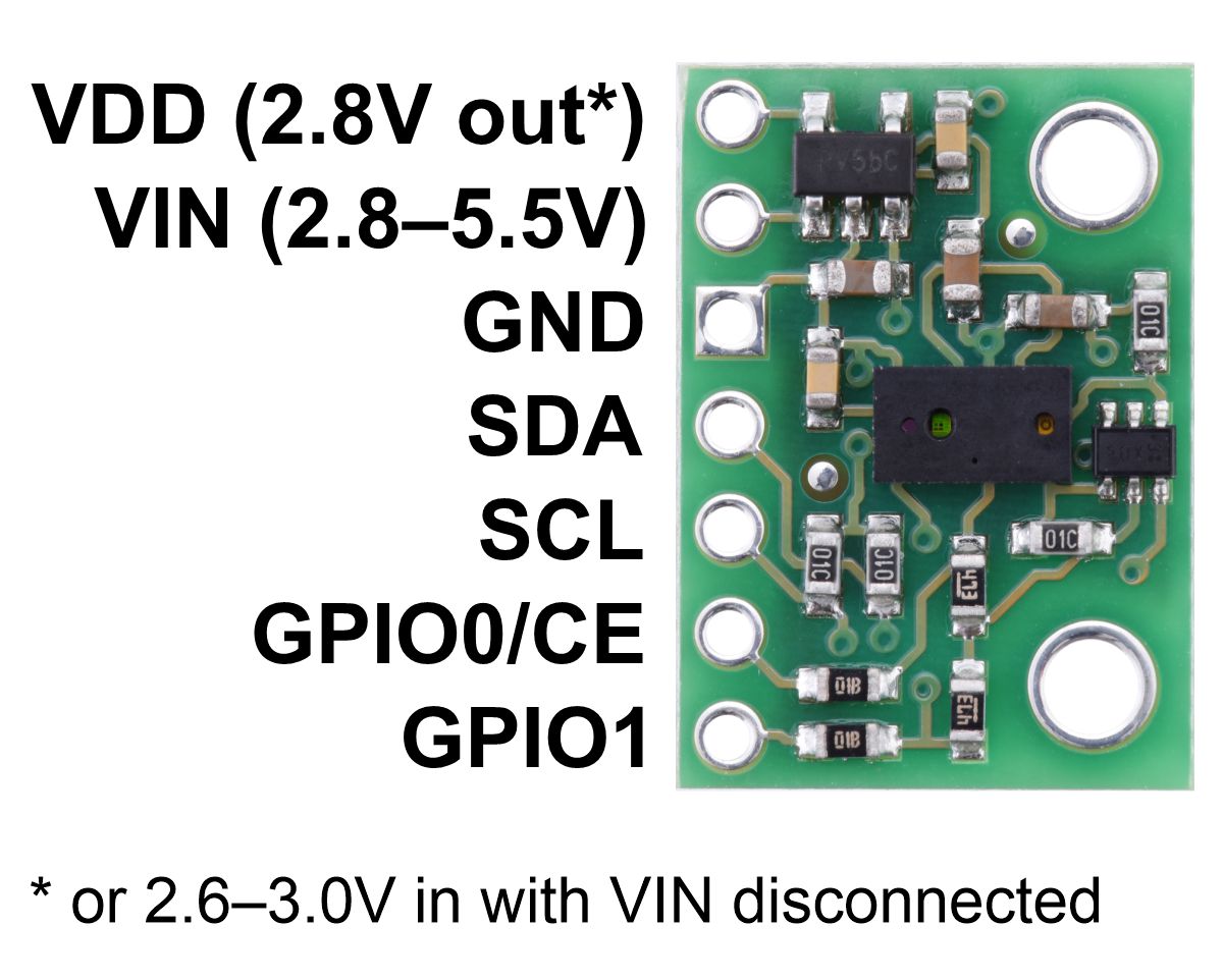
| VDD | Regulated 2.8 V output. Up to around 100 mA is available to power external components. (If you want to bypass the internal regulator, you can instead use this pin as a 2.6 V to 3.0 V input with VIN disconnected.) |
| VIN | This is the main 2.8 V to 5.5 V power supply connection. The SCL and SDA level shifters pull the I²C lines high to this level. |
| GND | The ground (0 V) connection for your power supply. Your I²C control source must also share a common ground with this board. |
| SDA | Level-shifted I²C data line: HIGH is VIN, LOW is 0 V |
| SCL | Level-shifted I²C clock line: HIGH is VIN, LOW is 0 V |
| GPIO0/CE | This pin is configured as a chip enable input on power-up of the VL6180X; the board pulls it up to VDD to enable the sensor by default. Driving this pin low puts the sensor into hardware standby. After the VL6180X powers up, this pin can be reconfigured as a programmable interrupt output (VDD logic level). This input is not level-shifted and it is not 5V-tolerant. |
| GPIO1 | Programmable interrupt output (VDD logic level). The VL6180X also drives this pin low when it is in hardware standby. This output is not level-shifted. |
At least four connections are necessary to use the VL6180X board: VIN, GND, SCL, and SDA. The VIN pin should be connected to a 2.8 V to 5.5 V source, and GND should be connected to 0 volts. An on-board linear voltage regulator converts VIN to a 2.8 V supply, which can be accessed via the VDD pin, for the VL6180X IC. Supply voltages between 2.6 V and 3.0 V can also be connected to VDD (with VIN left disconnected) to bypass the regulator and power the board directly.
The I²C pins, SCL and SDA, are connected to built-in level-shifters that make them safe to use at voltages above VDD; they should be connected to an I²C bus operating at the same logic level as VIN (or VDD, if powering the board through VDD).
The two GPIO pins are open-drain outputs pulled up to VDD by the board (although GPIO0 defaults to being a chip enable input). They are not connected to level-shifters on the board and are not 5V-tolerant, but they are usable as-is with many 3.3 V and 5 V microcontrollers: the microcontroller can read the sensor’s output as long as its logic high threshold is below VDD, and the microcontroller can alternate its own output between low and high-impedance states to drive the pin. Alternatively, our 4-channel bidirectional logic level shifter can be used externally with those pins.
Schematic diagram
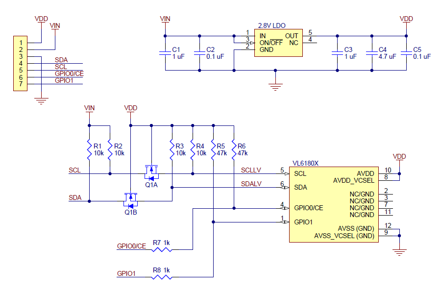 |
The above schematic shows the additional components the carrier board incorporates to make the VL6180 easier to use, including the voltage regulator that allows the board to be powered from a 2.6 V to 5.5 V supply and the level-shifter circuit that allows for I²C communication at the same logic voltage level as VIN. This schematic is also available as a downloadable PDF (90k pdf).
I²C communication
The VL6180X can be configured and its distance and ambient light readings can be queried through the I²C bus. Level shifters on the I²C clock (SCL) and data (SDA) lines enable I²C communication with microcontrollers operating at the same voltage as VIN (2.6 V to 5.5 V). A detailed explanation of the I²C interface on the VL6180X can be found in its datasheet (2MB pdf), and more detailed information about I²C in general can be found in NXP’s I²C-bus specification (1MB pdf).
The sensor’s 7-bit slave address defaults to 0101001b on power-up. It can be changed to any other value by writing one of the device configuration registers, but the new address only applies until the sensor is reset or powered off.
The I²C interface on the VL6180X is compliant with the I²C fast mode (400 kHz) standard. In our tests of the board, we were able to communicate with the chip at clock frequencies up to 400 kHz; higher frequencies might work but were not tested.
Sample Code
We have written a basic Arduino library for the VL6180X that makes it easy to interface this sensor with an Arduino or Arduino-compatible controller. The library makes it simple to configure the VL6180X and read the distance and ambient light level data through I²C. It also includes example sketches that show you how to use the library.
Protocol hints
The datasheet provides a lot of information about this sensor, but a lot of essential info – including a mandatory initialization sequence – can only be found in other documents. Picking out the important details can take some time. Here are some pointers for communicating with and configuring the VL6180X that we hope will get you up and running a little bit faster:
- Unlike many other I²C sensors from ST, which use 8-bit register addresses, the VL6180X uses 16-bit register addresses.
- The sensor must be initialized with a particular sequence of settings on power-up or reset. This sequence is not covered in the datasheet, but it can be found in ST application note AN4545 (706k pdf) and design tip DT0037 (386k pdf). (Our Arduino library includes a function that performs this initialization.)
- The two documents above can also help you understand basic procedures for configuring the VL6180X and getting readings from it. Additional documents, providing details on many other aspects of the VL6180X, can be found on ST’s product page for the VL6180X.
- Both distance and ambient light measurements can be performed in either single-shot or continuous mode. In either mode, once each measurement is started, you must poll a status register to wait for it to complete. In continuous mode, you should ensure that the inter-measurement period you select is longer than the time it takes to actually perform each measurement.
Range scaling factor
Although the VL6180X specifications state a maximum “guaranteed” range of 10 cm, the sensor can report distances of up to 20 cm with its default settings. By configuring a range scaling factor, the potential maximum range of the sensor can be increased at the cost of lower resolution. Setting the scaling factor to 2 provides up to 40 cm range with 2 mm resolution, while a scaling factor of 3 provides up to 60 cm range with 3 mm resolution. In all cases, the reading is given as a number between 0 and 200; with the default 1× scaling, this corresponds directly to a distance in mm, but with 2× or 3× scaling, the raw reading will represent a measurement in units of 2 mm or 3 mm, respectively (so the reading should be multiplied by 2 or 3 to obtain a result in millimeters).
Range scaling is not mentioned in the VL6180X datasheet as of Rev 7, but it is available in the VL6180X API provided by ST (STSW-IMG003). Our Arduino library also provides functions to set the range scaling factor.
Pololu’s family of carriers for ST time-of-flight distance sensors
We make pin-compatible carriers/breakout boards for several different ST time-of-flight (ToF) ranging sensors, as shown in the table below. They all function as tiny lidar systems featuring an integrated 940 nm Class 1 (i.e. invisible and eye-safe) laser, and they are all based on the same FlightSense technology, which precisely measures how long it takes for emitted pulses of infrared laser light to reach the objects and be reflected back to a detector. This approach ensures absolute distance measurements independent of ambient lighting conditions and target characteristics (e.g. color, shape, texture, and reflectivity), though these external conditions do affect the maximum range of the sensor. These sensors are all capable of 1 mm resolution, with some limitations on some versions.
 VL6180X carrier |
 VL53L4CD carrier |
 VL53L0X carrier |
 VL53L1X carrier |
 VL53L3CX carrier |
 VL53L5CX carrier |
 VL53L7CX carrier |
 VL53L8CX carrier |
|
|---|---|---|---|---|---|---|---|---|
| Maximum range:(1) | 60 cm | 120 cm | 200 cm | 400 cm | 500 cm | 400 cm | 350 cm | 400 cm |
| Minimum range: | ~10 mm | 1 mm | ~30 mm | 40 mm | 10 mm | 20 mm | ||
| Field of view: | 25° | 18° | 25° | 15° to 27° diagonal, programmable |
25° | 65° diagonal, up to 8×8 zones |
90° diagonal, up to 8×8 zones |
65° diagonal, up to 8×8 zones |
| Other features: | ambient light sensing, low memory footprint(2) |
low memory footprint(2), ultra-low power mode |
low memory footprint(2) | low memory footprint(2), ultra-low power mode |
multi-target detection, ultra-low power mode |
multi-target detection | multi-target detection | multi-target detection, improved performance in ambient light |
| Maximum update rate:(1) | ~150 Hz | 100 Hz | 50 Hz | 100 Hz | 125 Hz | 60 Hz | ||
| Operating voltage range: | 2.6 V to 5.5 V | 2.5 V to 5.5 V | 3.2 V to 5.5 V | |||||
| Regulator voltage: | 2.8 V | 3.3 V | 1.8 V and 3.3 V | |||||
| Typical active-ranging supply current: |
25 mA | 25 mA | 20 mA | 20 mA | 20 mA | 100 mA | ||
| Peak supply current: | 40 mA | 150 mA | ||||||
| Interface: | I²C | I²C, SPI | ||||||
| Dimensions: | 0.5″ × 0.7″ | 0.5″ × 0.9″ | ||||||
| 1-piece price: | $19.95 | $13.95 | $19.95 | $22.95 | $19.95 | $19.95 | $19.95 | $24.95 |
| 1 Effective range and update rate depend on configuration, target, and environment. 2 Suitable for use with typical 8-bit MCUs. |
||||||||
Most of these carriers have the same physical dimensions (0.5″ × 0.7″) and work in 3.3 – 5 V systems (thanks to their integrated linear regulators and level-shifters), and they can all be controlled through an I²C interface. However, they have different APIs and memory requirements, so software will generally need to be rewritten when switching between sensors in an application, and versions with higher memory requirements are generally not suitable for use with typical 8-bit microcontrollers.
Related products


Related categories


Home | Forum | Blog | Support | Ordering Information | Lists | Distributors | BIG Order Form | About | Contact
© 2001–2026 Pololu Corporation
