5V 3A BEC Step-Down Voltage Regulator

This switching step-down (or buck) voltage regulator takes an input voltage of up to 23 V and reduces it to 5 V with a maximum output current of 3 A. It has 22-AWG input leads with stripped and tinned terminations and a 3-pin “JR”-style servo connector on the output lead.
| Description | Specs (7) | Pictures (0) | Resources (0) | FAQs (0) | On the blog (0) | Distributors (0) |
|---|
Overview
This type of buck (step-down) voltage regulator is commonly used in the RC hobby industry, where it is called a “Battery Elimination Circuit” (BEC). It can convert a higher voltage, such as from a motor battery, to a lower 5 V level for powering devices like RC receivers and servos, removing the need for a separate battery. This switching regulator takes an input voltage between 5 and 23 V and reduces it to 5 V, providing up to 3 A of output current. However, the maximum achievable output current of the regulator depends on many factors, including the ambient temperature, air flow, heat sinking, and the input voltage. Note that the ferrite bead shown in the product picture might not be included.
We also carry a similar voltage regulator that is more efficient, works with input voltages as high as 38 V, and includes reverse voltage protection.
Specifications
- input voltage: 5 V to 23 V
- continuous output current: 3 A
- output voltage: 5 V
- 330 kHz switching frequency
- 8 mA typical no-load quiescent current
- small size: 1.5" × 0.6" × 0.4" (38 × 15 × 10 mm)
- weight: 0.4 oz (12 g)
Using the Regulator
Connections
Two 7 cm 22-AWG wires with stripped, tinned terminations are attached to the board as input leads. The output lead is a 15 cm 3-wire servo cable with a “JR” style connector on the end, although the white signal line is not used by the regulator. The cable has a female connector that fits nicely with 0.1" male headers, but these connectors are often referred to as “male” in the RC hobby industry. The connector on the output end is the same as what is found on most servos:
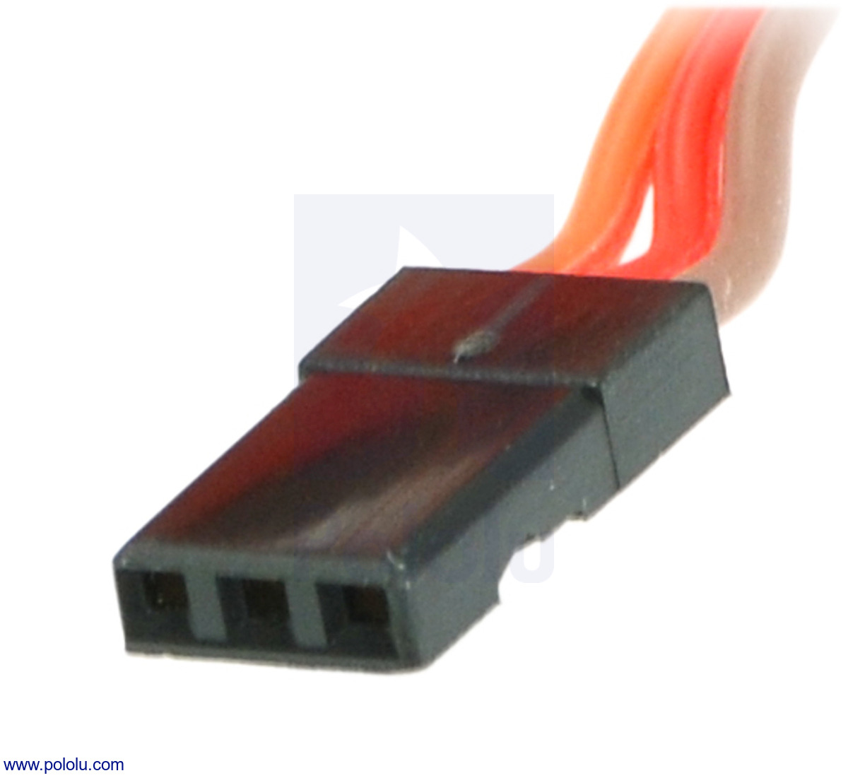 |
Servo cable color convention
- brown or black = ground (GND, battery negative terminal)
- red = servo power (Vservo, battery positive terminal)
- orange, yellow, or white = servo control signal line; not used by this regulator
Output Current
The regulator’s output current is rated at 3 A continuous. However, over-temperature protection can kick in at lower output currents. Therefore, the maximum achievable output current of the regulator depends on many factors, including the ambient temperature, air flow, heat sinking, and the input voltage. In our tests at room temperature, a continuous output current of 3 A was available across nearly the entire input voltage range, although the regulator began to overheat before reaching 3 A at higher input voltages. These continuous current characteristics are limited by thermal dissipation; the regulator can output higher currents for several seconds or even tens of seconds, depending on how low the current is during the off-peak periods. Higher continuous output current can be achieved by reducing the input voltage or by cooling the board by adding a heat sink or a fan.
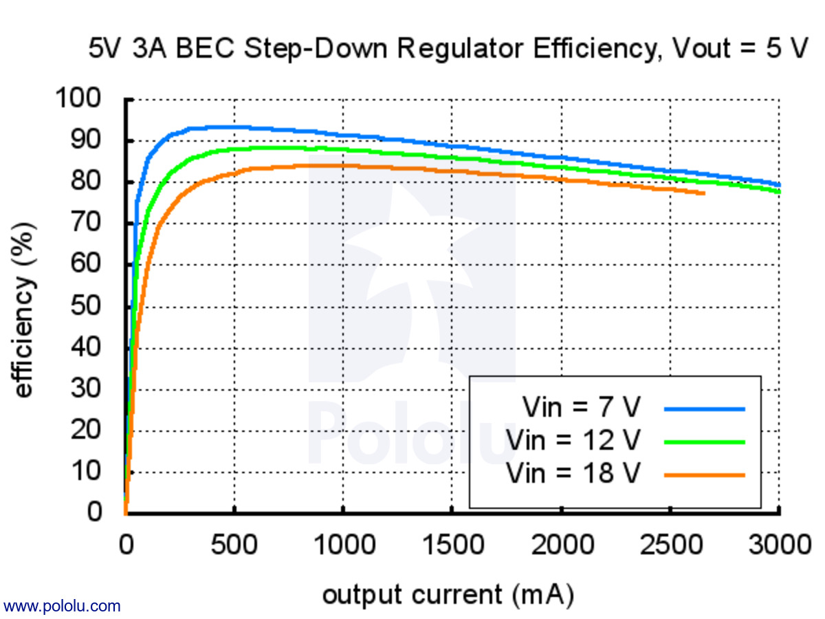
Typical Efficiency
The efficiency of a voltage regulator, defined as (Power out)/(Power in), is an important measure of its performance, especially when battery life or heat are concerns. As shown in the graph below, this switching regulator typically has an efficiency of 80 to 90%. For example, when regulating 12 V to 5 V with an output current of 1.5 A, the efficiency is above 85%. Since the output power is (Output current)×(Vout) = 1.5 A × 5 V = 7.5 W, the input power will be a bit under 9 W, with about 1.2 W of heat dissipated in the regulator. The input current can then be calculated as 9 W/12 V = 0.75 A. This is far better than a linear voltage regulator, which would require an input current of 1.5 A and 18 W, wasting 10.5 W instead of the 1.2 W lost in this switching regulator.
 |
Related products


Home | Forum | Blog | Support | Ordering Information | Lists | Distributors | BIG Order Form | About | Contact
© 2001–2026 Pololu Corporation
