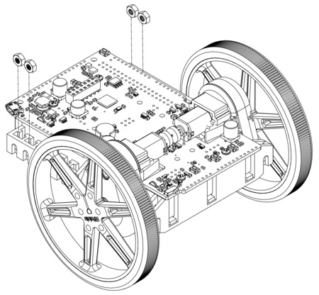
See Section 1.1 for a diagram to help you identify the contents of the Balboa 32U4 robot kit.
Preparing electronics
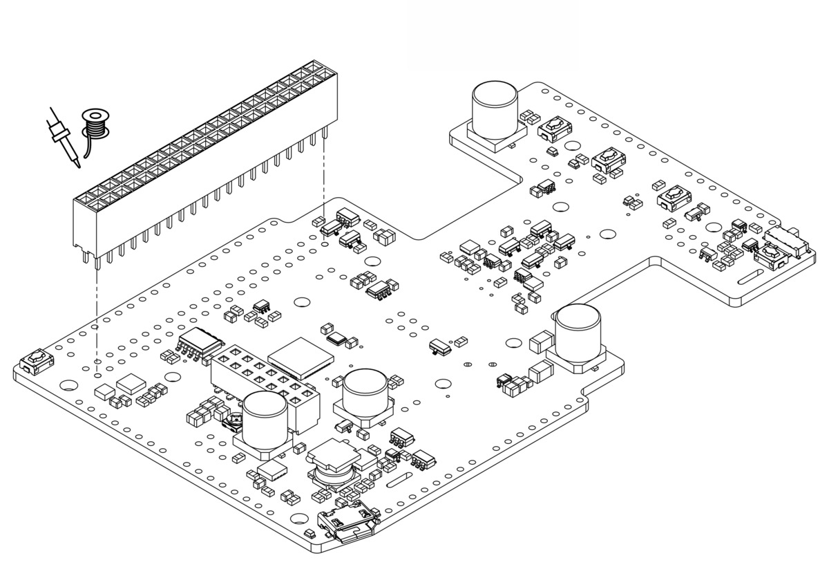
- Before doing any assembly, now is a good time to solder in the buzzer to the Balboa 32U4 control board.
- Optional: This is a convenient time to add any other optional electronics or headers (such as a 2×20 female header for mounting a Raspberry Pi).
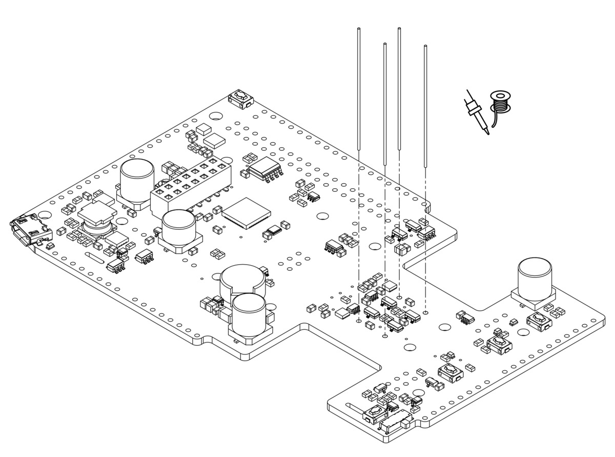
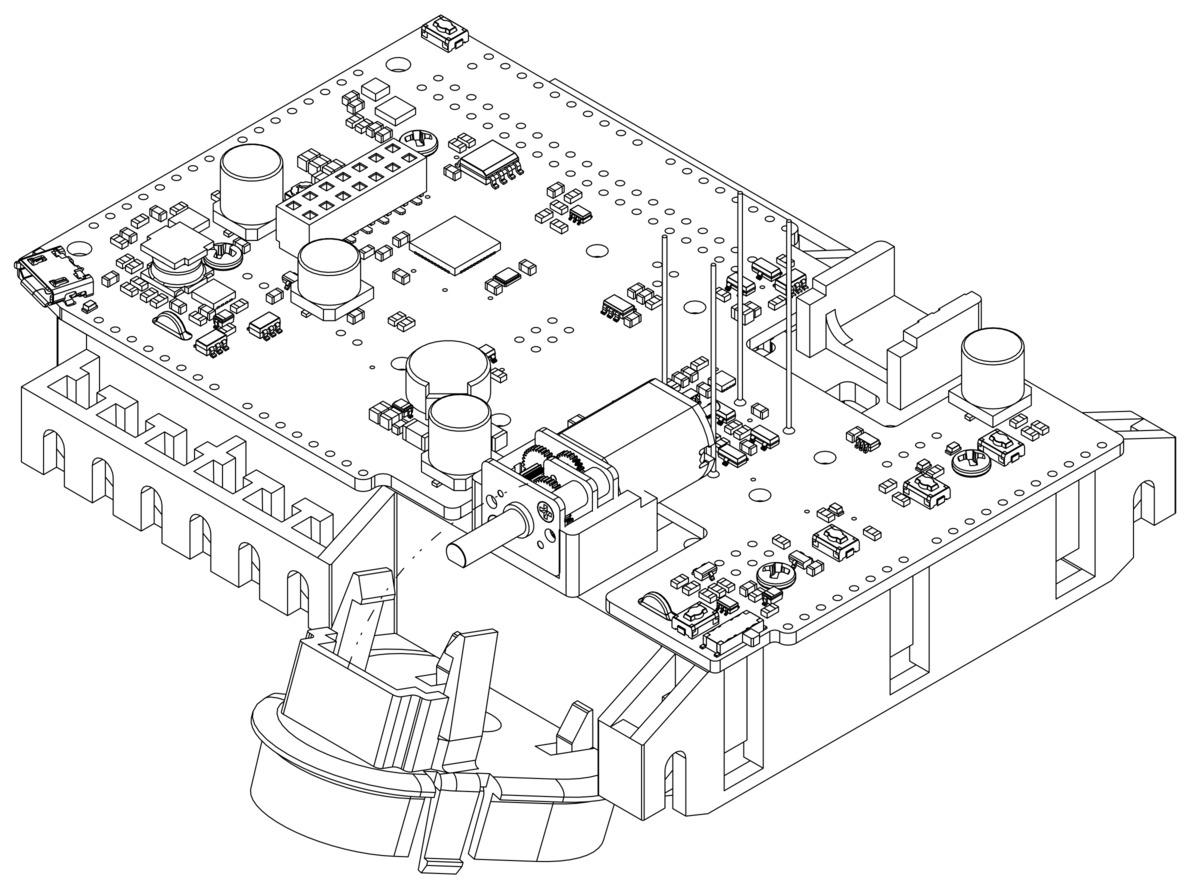
- Cut two of the included jumper wires in half and solder them to the motor output pins with the excess wire protruding out of the top of the board as shown.
Battery contacts and electronics
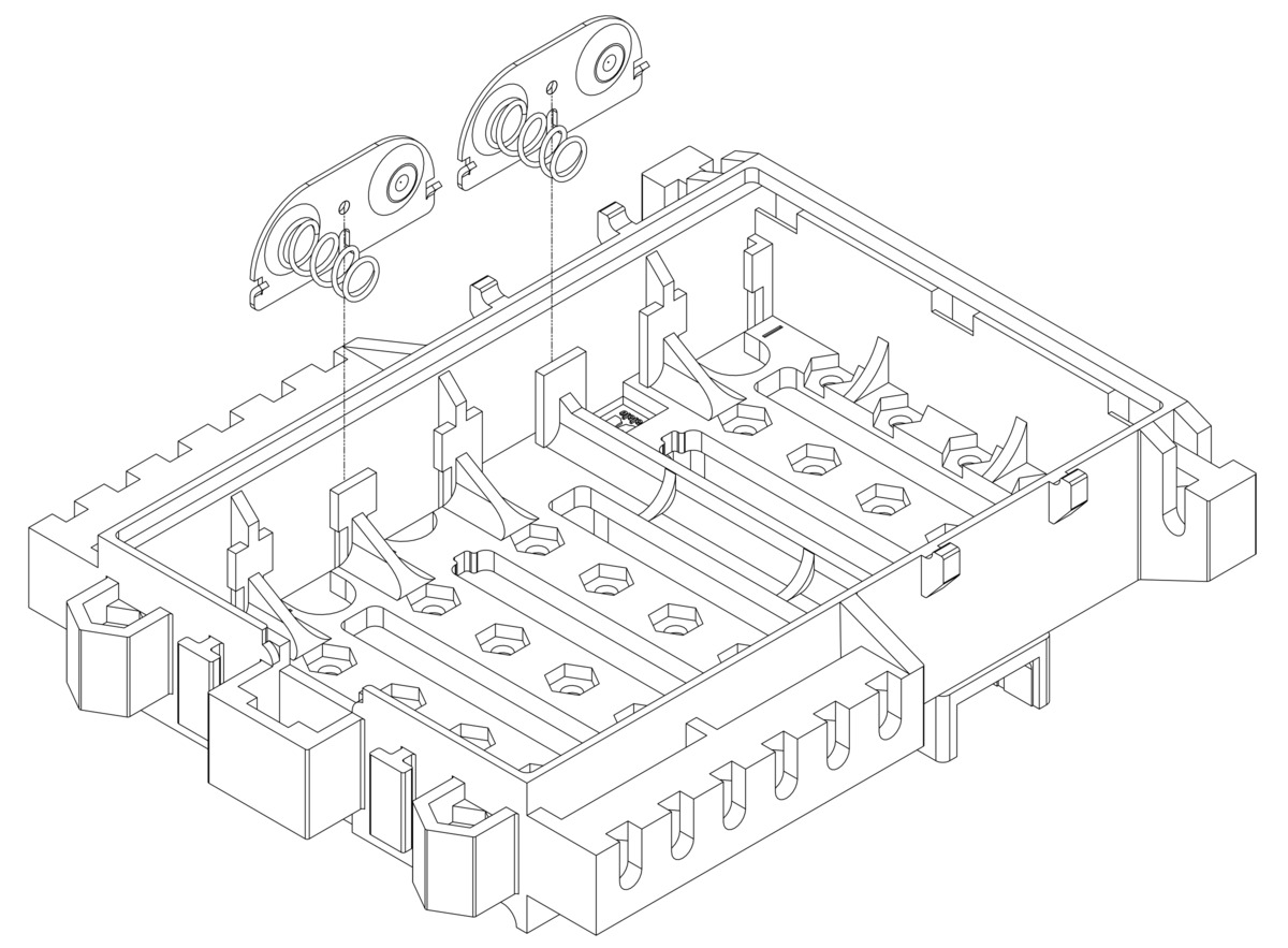
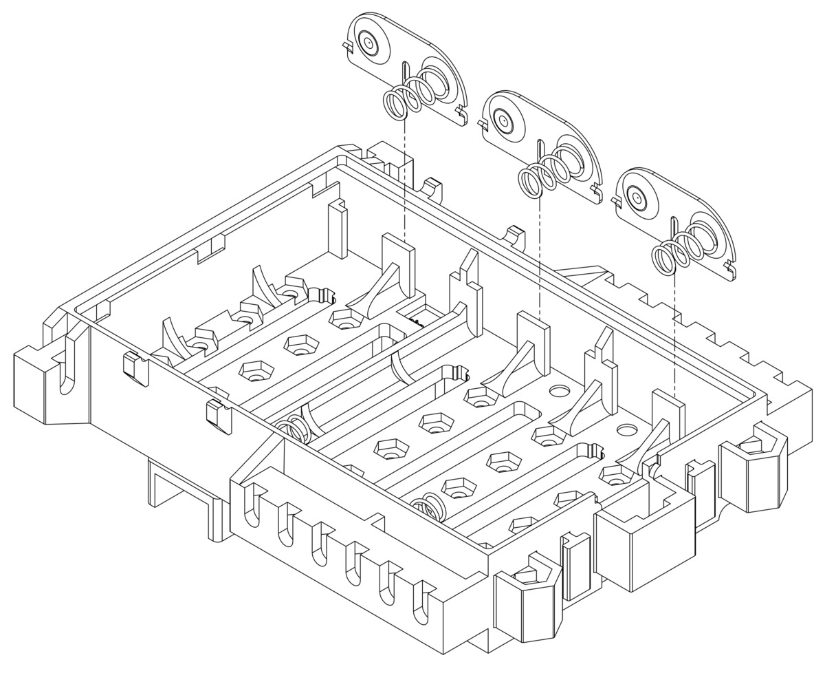
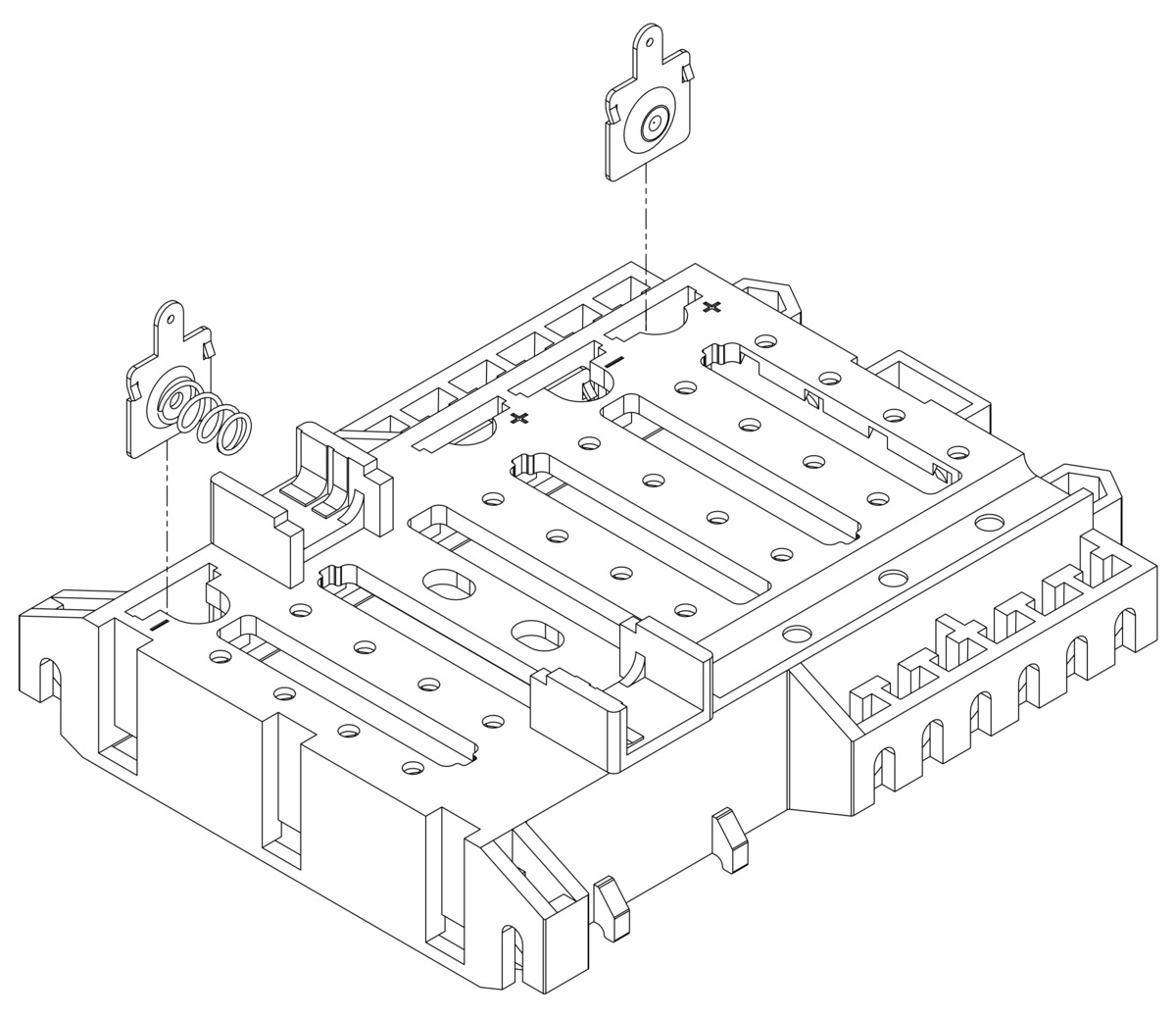
- Set aside the Balboa 32U4 control board and insert the double-sided battery contacts as shown below.
Note: there are two different kinds of double-sided battery contacts, one with the spring on the left and one with the spring on the right, and they must be installed in the correct locations to make proper contact with the batteries.
- Flip the chassis over and insert the two individual battery contact terminals into the top of the chassis.
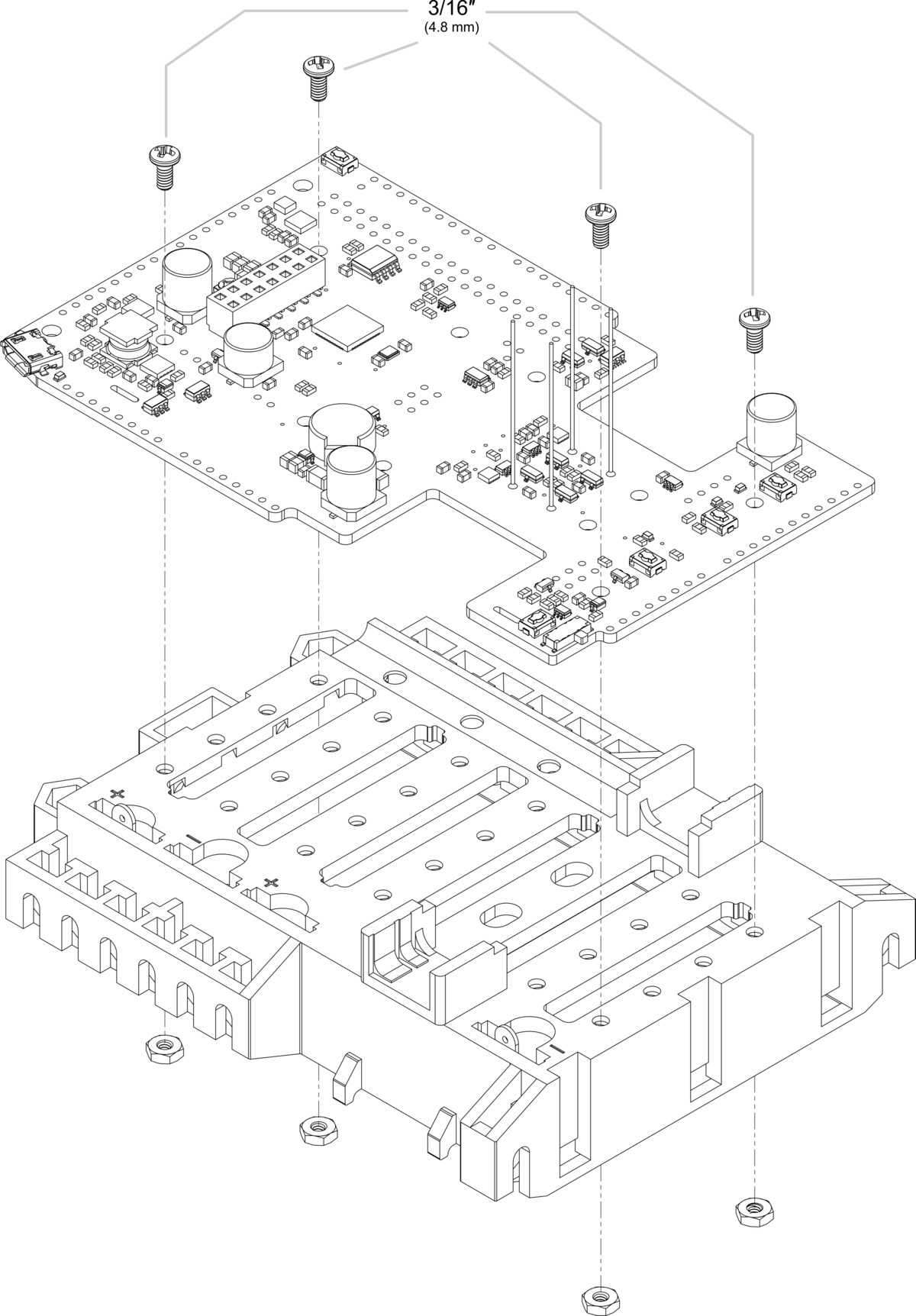
- Place the Balboa 32U4 control board on the chassis, making sure the battery terminals insert into the slots on the board. Secure the board in place using the four included #2-56 screws and nuts.
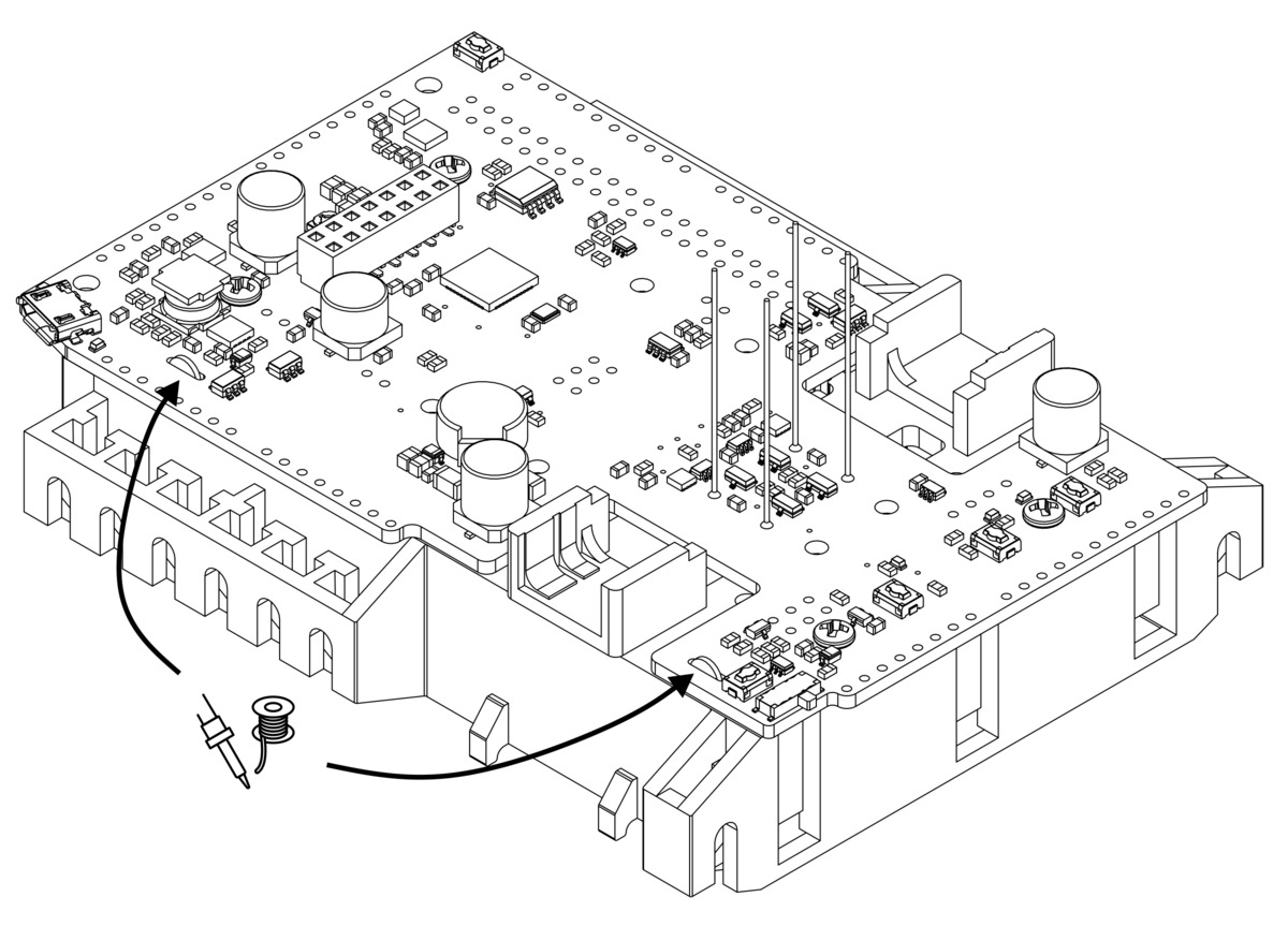
- Solder the battery terminals to the Balboa 32U4 control board.
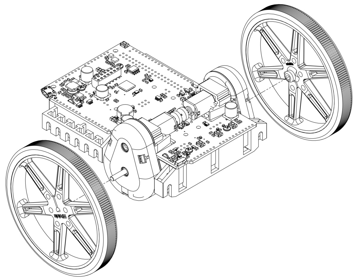
Motors and encoders
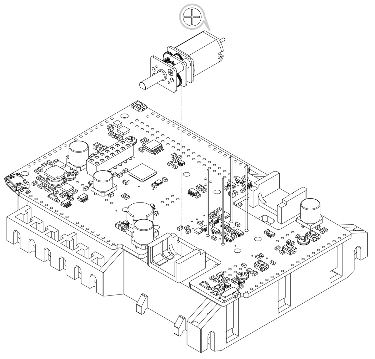
- Place a motor into one of the motor slots on the chassis with its positive terminal toward the longer end of the board, as indicated. (When the Balboa is fully assembled and balancing upright, the positive motor terminal should be closer to the top.) When properly seated in the slot, the face plate of the motor gearbox will be flush with the edge of the slot.
- Install the motor retention clip/gearbox housing by aligning the two tabs on the chassis with the slots on the clip, sliding the clip up until the tabs are seated in the slots, and rotating the clip into position until you hear it click into place.
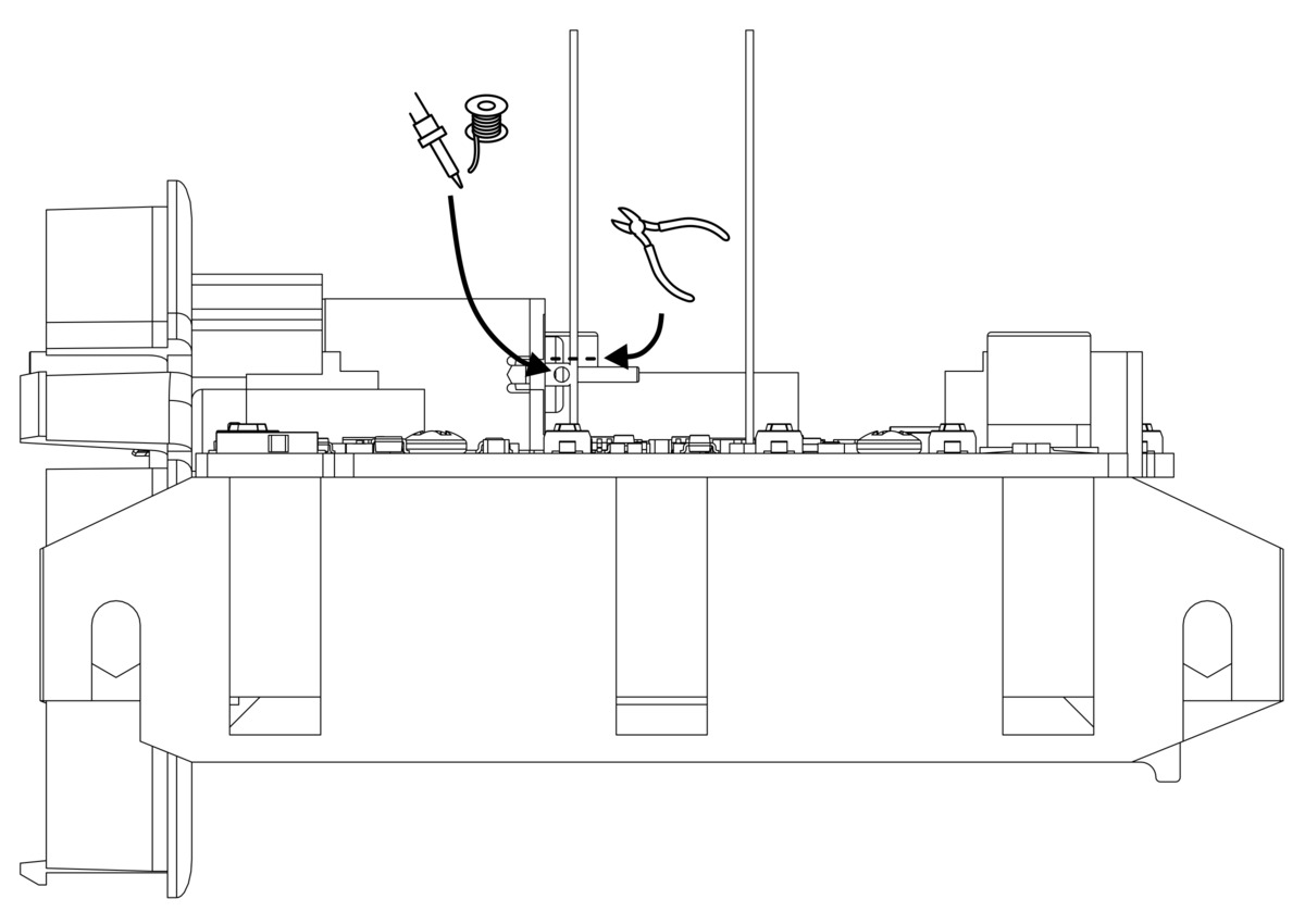
- Clip the motor wires to an appropriate length and solder them to the motor terminals.
- Install the magnetic encoder disc on the motor’s extended motor shaft. It should be flush with the end of the shaft and align with the sensors on the Balboa 32U4 control board.
- Repeat steps 8 through 11 for the second motor (again making sure the + terminal of the motor is toward the longer end of the board).
Gearboxes
- Choose a gear ratio to use with your Balboa. There are five combinations of the included gears to choose from, each resulting in a different ratio. The Balboa kit gear ratio chart (447k pdf) details the possible gear ratios and can be used to help identify the gears if printed at 100% scale. Note that the tooth count is also indicated on the side of the output gears.
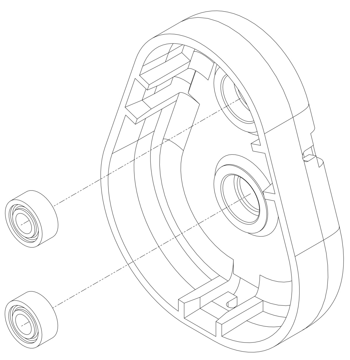
- Press two ball bearings into the gearbox cover.
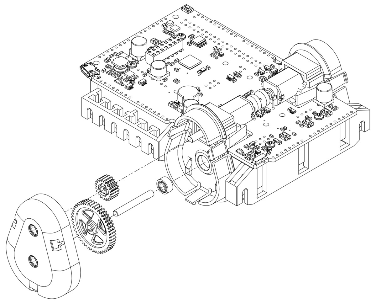
- Place another ball bearing into the gearbox housing on the chassis and insert the round side of the 3 mm D-shaft (the D-shape should be facing outwards). Next, press your selected gears onto the two shafts, making sure they align properly, and install the gearbox cover. Double check that all three clips have snapped into place.
- Repeat steps 14 and 15 to assemble the other gearbox, making sure to use the same gear ratio.
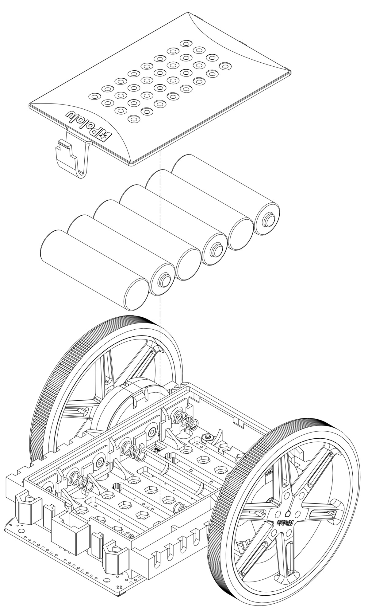
Wheels and batteries
- Press the wheels onto the output shafts of the gearboxes until the shaft is flush with the outer surface of the wheel. One way to do this is to set the wheel on a flat surface and line the chassis up with it so that the flat part of the motor’s D-shaft aligns correctly with the wheel. Then, lower the chassis, pressing the motor shaft into the wheel until it contacts the surface.
- Install six new or freshly charged AA batteries in the battery compartment (we recommend using rechargeable AA NiMH cells). The correct orientation for the batteries is indicated by the battery-shaped holes in the Balboa chassis as well as the + and – indicators in the battery compartment of the chassis. Once they are installed, secure the battery compartment cover.
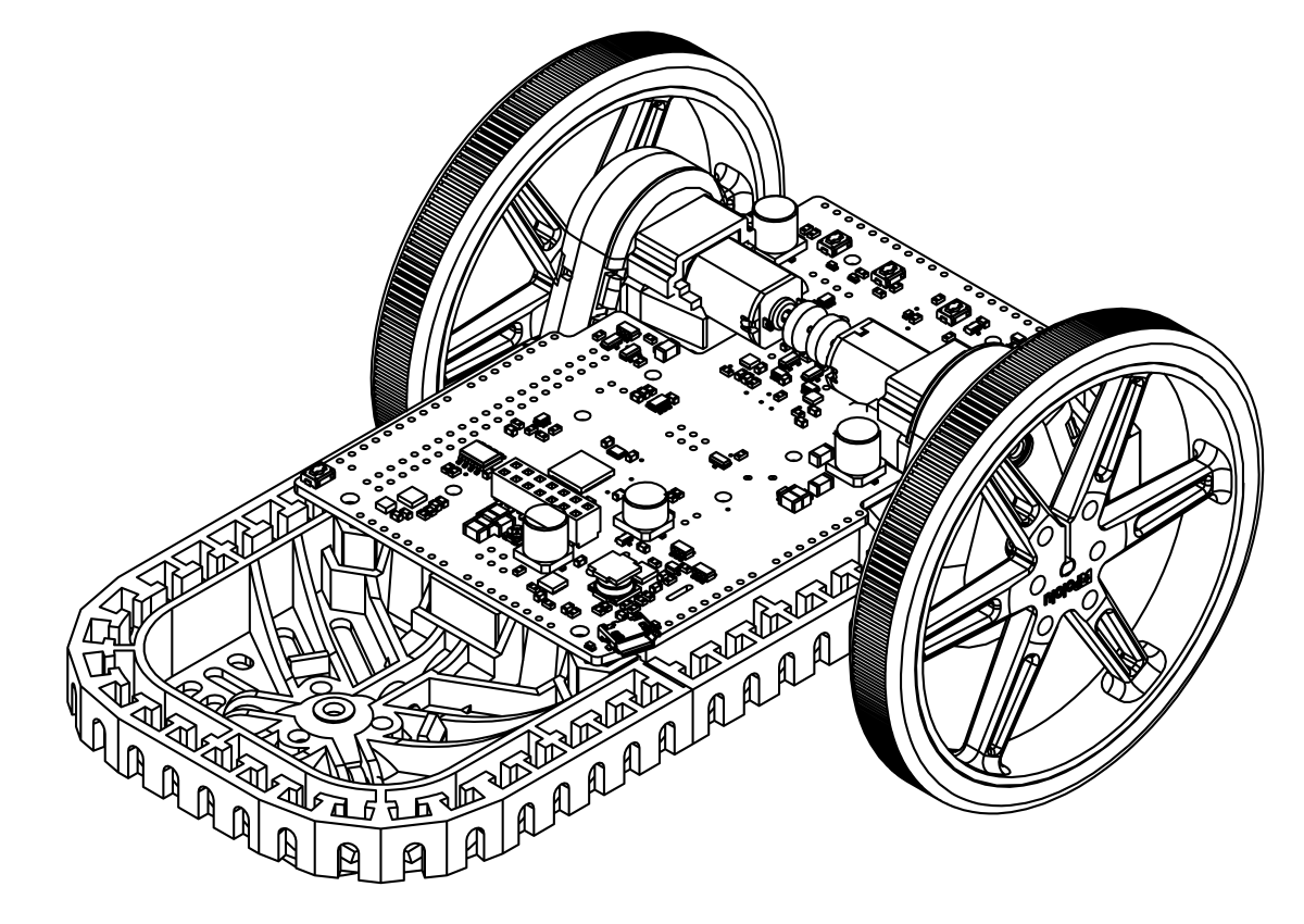
The basic assembly of your Balboa chassis is now complete!
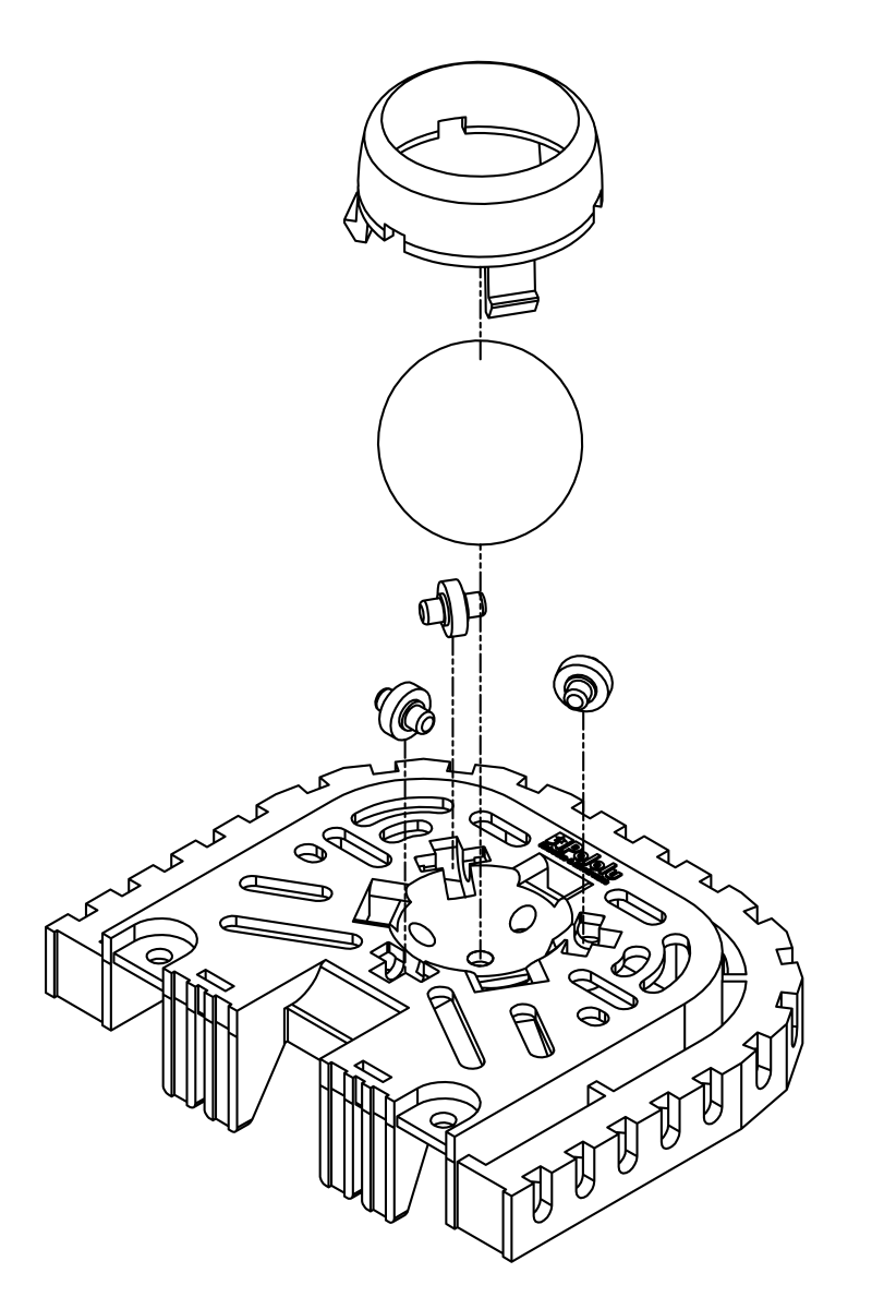
Adding the Stability Conversion Kit
If you have the Stability Conversion Kit for the Balboa, you can use it to provide a smooth third point of contact for traditional differential-drive applications. Additionally, the extension piece can be used (with or without the ball caster) to make the Balboa taller and give it more mounting options. To assemble the optional ball caster, start by placing the rollers into the cutouts in the Stability Conversion Kit. Next, place the 1" plastic ball on the top of the three rollers and push the ball caster retention clip over the ball and into the chassis so the three legs snap into their respective mounting slots. You should hear a clicking sound when the retention clip is properly engaged.
 |
Align the slots on the Stability Conversion Kit with the rails on the Balboa chassis and slide the two pieces together until the clips snap into place. Optionally, you can use the two mounting holes (located just outside of the clips) to further secure the Stability Conversion Kit to the Balboa chassis. These mounting holes are intended for M3 screws and nuts.
To remove the Stability Conversion Kit from the Balboa, push on the extension piece while simultaneously pulling back on the clips. If you have the Balboa 32U4 control board (or other electronics) mounted on the Balboa chassis, you might consider using a small screwdriver to help reach the clips.
Adding protection against falls
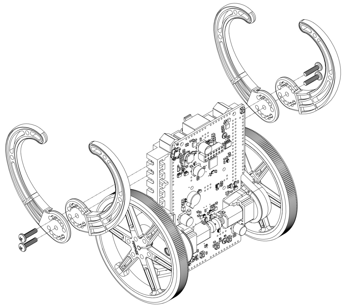
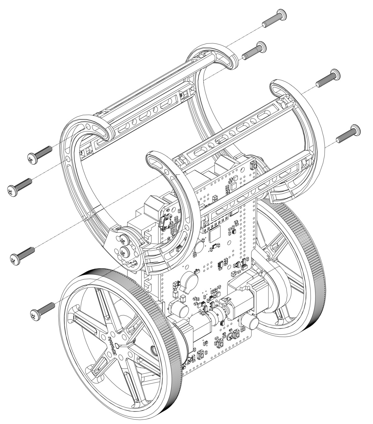
When you are using the Balboa as a balancing robot, it is important to protect the electronics from hard falls that could damage them. In general, we recommend running the Balboa on soft surfaces, such as carpet. It also helps to install the bumper cage kit so the bumper will hit the ground before the electronics. The bumper cage has numerous mounting holes that can be used to adjust the positioning. Details about the various mounting options can be found in Section 3.12. The bumper cage mounts to the side rails of the Balboa chassis with M3 screws (12 mm length) and nuts. The bumper cage is made up of four bumper skids and four bumper cage cross bars. The pictures below show the process of mounting the bumper skids.
 |
 |
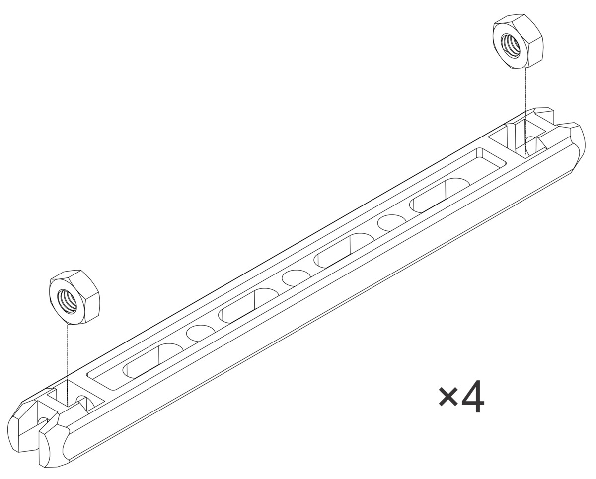
The bumper cage cross bars (shown below) help stabilize the bumper cage and can be installed in various locations, as needed, along the slots or in the designated mounting holes on each bumper skid. They can be rotated before tightening down the mounting screws to better accommodate additional hardware.
The bumper cage also comes with two spacers, which allow just one side of the bumper cage to be used. This is achieved by substituting one set of bumper skids with the spacers.
Home-made bumper cages could also be used to not only protect electronics, but also add uniqueness and creativity to your robot. The pictures below show two such home-made examples:
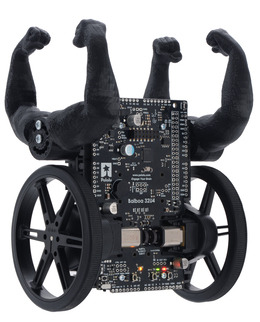 | Balboa 32U4 Balancing Robot with 80×10mm wheels and 3D-printed arms. |
|---|
|
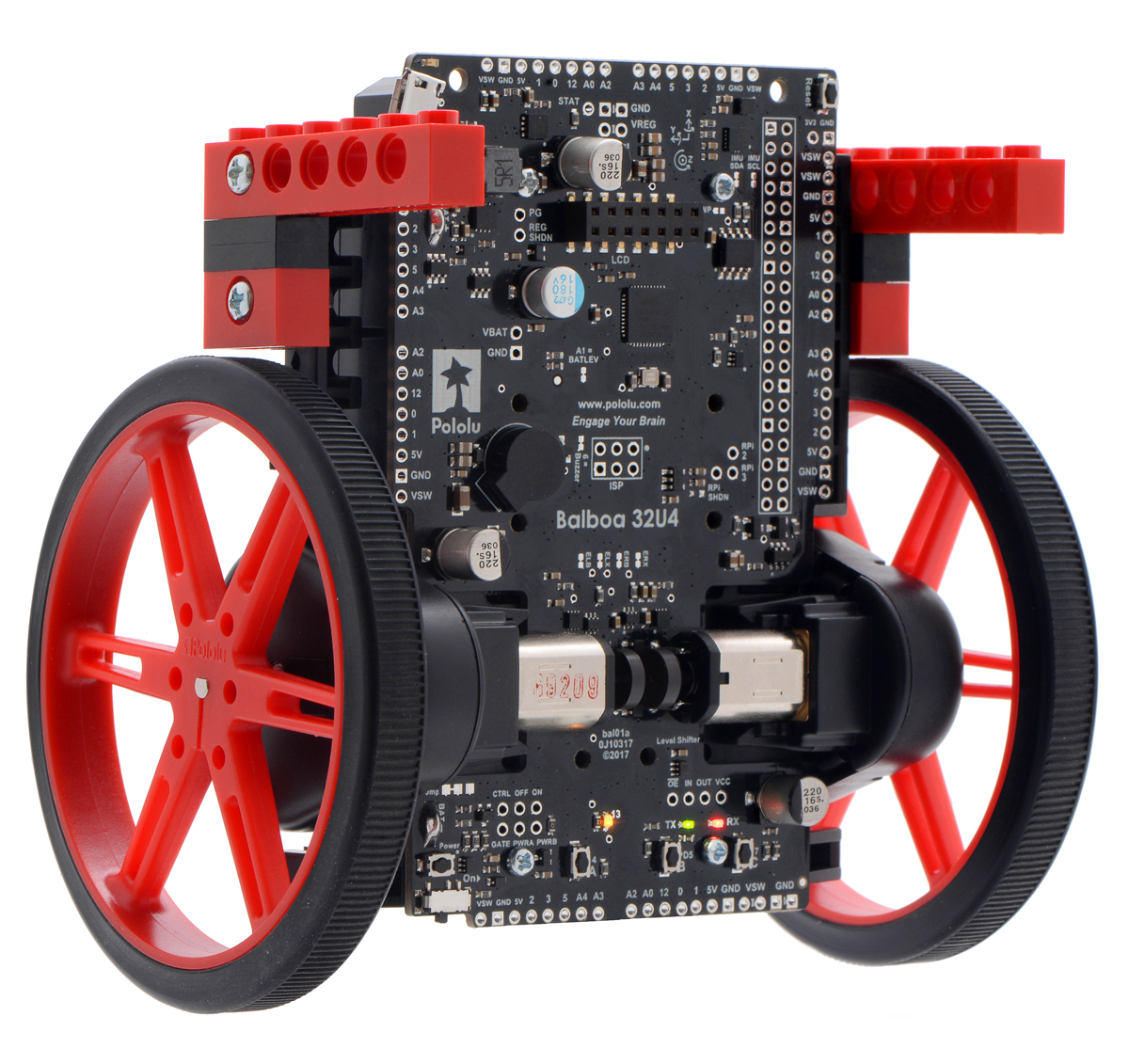
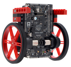 | Balboa 32U4 Balancing Robot with 80×10mm wheels and arms made from LEGO blocks. |
|---|
|
We have made the arms in the left picture available on Thingiverse so those with access to 3D printers can print their own. For everyone else, you can improvise your own bumpers using everyday objects, like LEGO blocks, wood, or cardboard, and mount them to the side rails of the chassis with M3 screws and nuts (the screws in the LEGO-arm picture are 12 mm long).