Support » Pololu Balboa 32U4 Balancing Robot User’s Guide » 3. Balboa 32U4 in detail »
3.12. Bumper cage
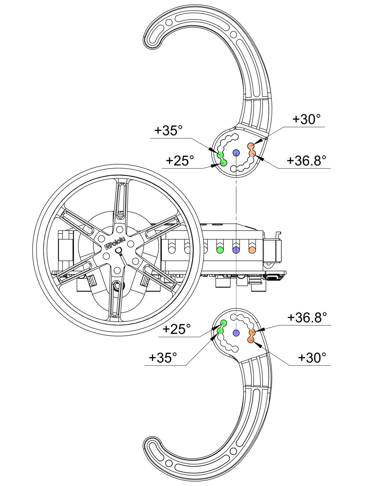
Along with protecting the robot during falls or collisions, the bumper cage can be used to hold the robot in a particular position when not balancing. See the instructions in Section 4 for details for how to put it together. The diagrams below can be used to help identify which mounting holes to use when assembling the bumper cage to achieve particular angles (with respect to the horizontal). These diagrams all use the 80mm wheel; note that the angles will differ when using different diameter wheels.
 |
Note that the bumper skids on either side of the robot can be adjusted independently from the other side, allowing for asymmetric configurations. The arms can be flipped to achieve some additional angles as shown below.
 |
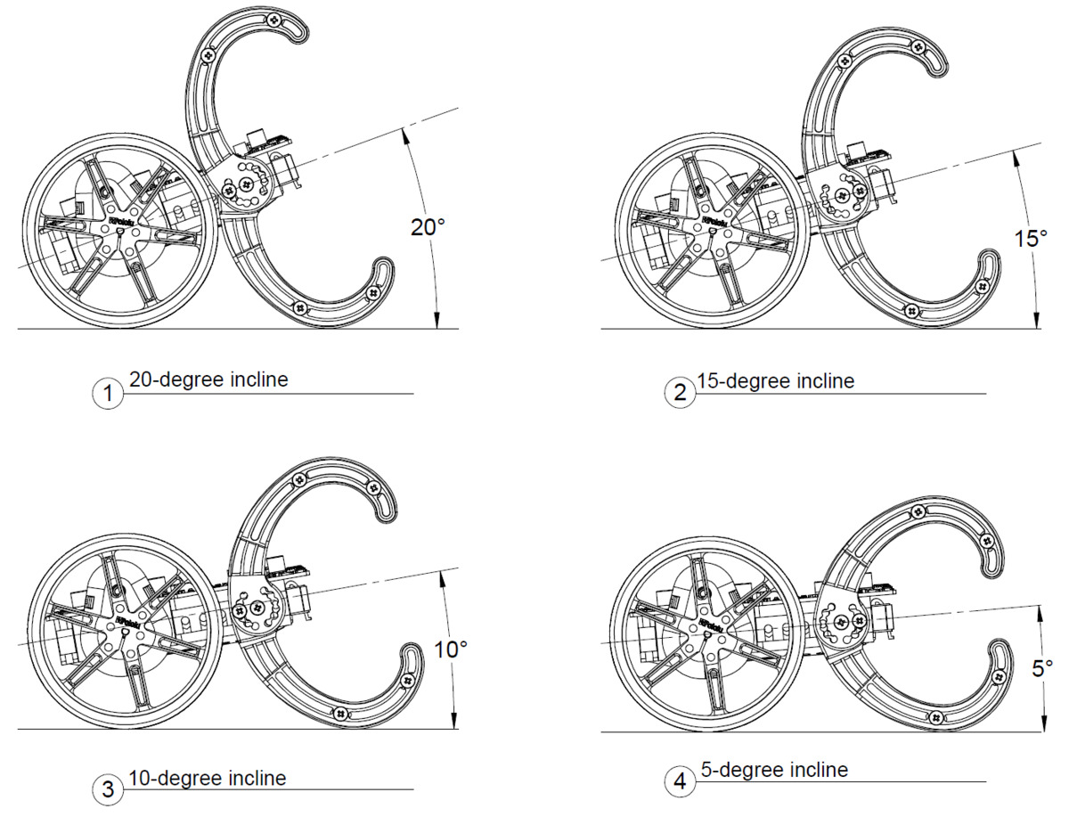
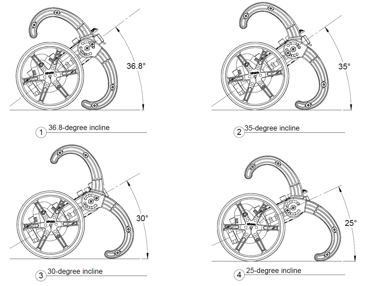
The diagrams below show the bumper cage assembled and installed on the Balboa in various positions; the top pictures show various inclined positions available, while the bottom picture shows the declined positions.
 |
 |
 |
 |
These diagrams are also available in a downloadable PDF (2MB pdf).
Additionally, the included spacers can be used in place of the pair of bumper skids on either side of the robot and allow you to use just one side of the bumper cage.
 |


Home | Forum | Blog | Support | Ordering Information | Lists | Distributors | BIG Order Form | About | Contact
© 2001–2026 Pololu Corporation
