Support » Pololu Zumo 32U4 Robot User’s Guide » 3. The Zumo 32U4 in detail »
3.5. Front sensor array (line and proximity sensors)
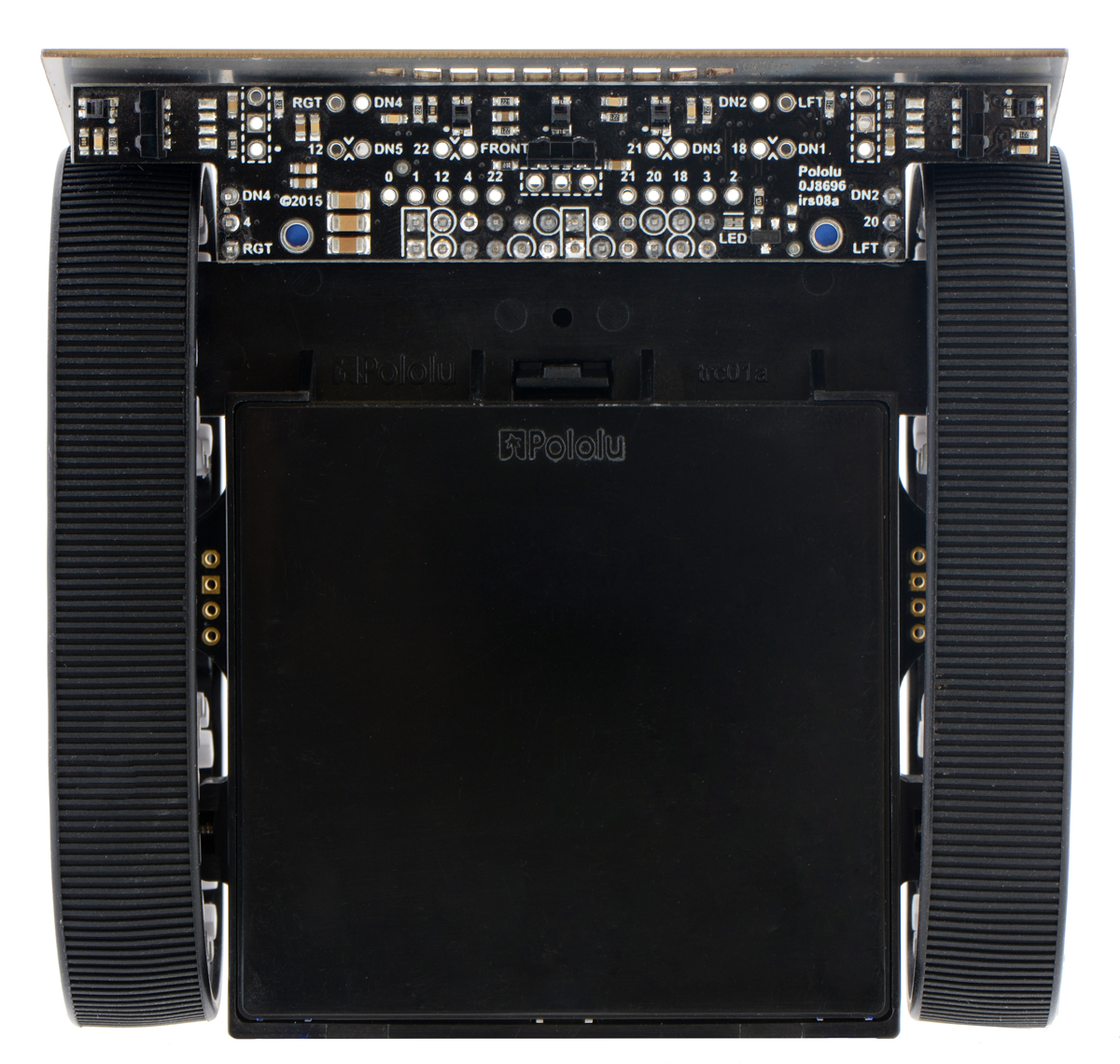 |
The Zumo 32U4 Front Sensor Array is a separate board that attaches to the main board. The board features five line sensors and three proximity sensors, though by default, you can only have six of these eight sensors connected to the Zumo’s microcontroller at any given time.
The five line sensors face downward and can help the Zumo distinguish between light and dark surfaces. They can also be used to detect sources of infrared light, like the sun. Each reflectance sensor consists of a down-facing infrared (IR) emitter LED paired with a phototransistor that can detect reflected infrared light from the LED. The reflectance sensors operate on the same principles as our QTR-1RC sensor: the AVR uses an I/O line to drive the sensor output high, and then measures the time for the output voltage to decay. The IR emitters for the reflectance sensors are on by default, but they can be turned off by driving digital pin 11 low. The five line sensors are numbered 1 through 5, with line sensor 1 being the robot’s left-most sensor. In schematics and diagrams, they are referred to as DOWN1, DOWN2, DOWN3, DOWN4, and DOWN5. On the front sensor array, their signals are labeled DN1, DN2, DN3, DN4, and DN5. The part used for the line sensors is the Sharp GP2S60 compact reflective photointerrupter (164k pdf).
The three proximity sensors face in different directions away from the Zumo and can help detect nearby objects. They can also be used to detect commands from typical IR remote controls. The proximity sensors, like the line sensors, detect reflected IR light, but they are designed to only detect light that is turned on and off quickly at a frequency of 38 kHz. To read a proximity sensor, the AVR can enable the internal pull-up on the corresponding I/O line. When the sensor is active, it will drive the line low. The proximity sensors do not have IR emitters paired with them; instead they detect reflected 38 kHz IR light that comes from LEDs on the Zumo 32U4 Main Board, which are described in Section 3.6. The proximity sensors are named after the directions they face: left, right, or front. In schematics and diagrams, they are referred to as LEFT, RIGHT, and FRONT. On the front sensor array, their signals are labeled LFT, FRONT, and RGT. The part used for the proximity sensors is the Vishay TSSP77038 IR receiver module (268k pdf). The TSSP77038 has a fixed gain (sensitivity) that makes the sensor more predictable.
Each sensor output on the front sensor array is protected by a 220 Ohm resistor to help prevent short circuits when the AVR is driving the corresponding I/O line.
The infrared emitted by the line sensors can interfere with the proximity sensors and cause false readings, so it is recommended to turn off the line sensor emitters before using the proximity sensors. The Zumo32U4ProximitySensors class from the Zumo 32U4 Arduino library takes care of turning off the line sensor emitters.
Pin assignments
By default, the front sensor array supports these pin assignments:
- Pin A0 (18) is connected to line sensor 1 (DN1),
- Pin A3 (21) is connected to line sensor 3 (DN3).
- Pin 12 is connected to line sensor 5 (DN5).
- Pin A4 (22) is connected to the front proximity sensor.
- Pin A2 (20) is connected to either the left proximity sensor (LFT) or line sensor 2 (DN2), depending on the position of a jumper.
- Pin 4 is connected to either the right proximity sensor (RGT) or line sensor 4 (DN4), depending on the position of a jumper.
- Pin 11 is connected to the line sensor emitter control pin (LEDON).
The assembled versions of the Zumo 32U4 robot ship with jumpers selecting the left (LFT) and right (RGT) proximity sensors instead of down-facing DN2 and DN4, so these versions are configured for three down-facing sensors and all three proximity sensors by default.
The signals from the sensors can be remapped by soldering in a wire from the signal output to the desired I/O pin. You would also want to disconnect the sensor output from the standard I/O pin so that pin can be used for other purposes. For line sensor 1, line sensor 3, line sensor 5, and the front proximity sensor, disconnecting the sensor involves cutting a trace between the signal output and the standard I/O pin, which is labeled on the board. For the line sensor 2, line sensor 4, the left proximity sensor, and the right proximity sensor, you can simply move or remove the corresponding jumper.
Example remapping: using all the sensors
If you want to use all five line sensors and all three proximity sensors in one application, you can accomplish that by freeing up two I/O lines and remapping two of the pins. One way to accomplish this is by removing the Zumo’s display to free up pins 0 and 1. Next, configure the jumpers on the front sensor array to connect pin 4 to line sensor 4, and pin 20 to line sensor 2. Solder a wire from the right proximity sensor signal to pin 0, and solder a wire from the left proximity sensor to pin 1. You will need to modify your code to include the new pin assignments, and you should remove all display-related code.
Related products


Home | Forum | Blog | Support | Ordering Information | Lists | Distributors | BIG Order Form | About | Contact
© 2001–2026 Pololu Corporation
