Support » Pololu Zumo 32U4 Robot User’s Guide » 3. The Zumo 32U4 in detail »
3.4. Quadrature encoders
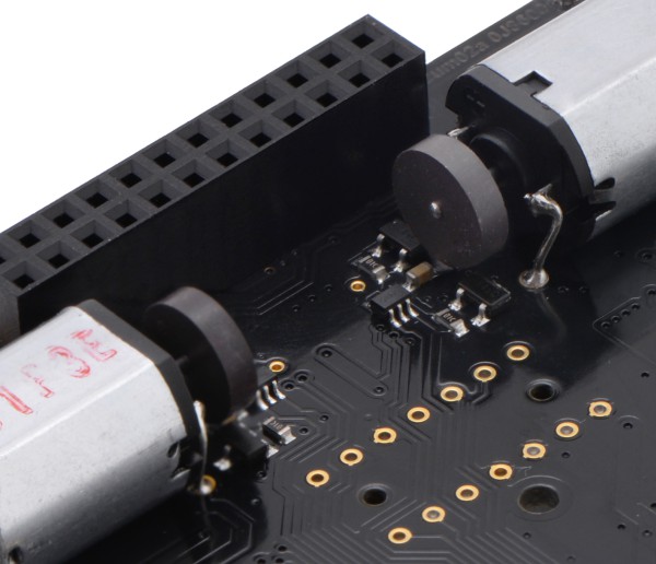 |
Each drive motor on the Zumo 32U4 has a corresponding quadrature encoder system consisting of a magnetic disc attached to the extended motor shaft and a pair of Hall effect sensors mounted to the underside of the main board. Other than the sensor orientation, these encoders work similarly to our magnetic encoder kits for micro metal gearmotors. They can be used to track the rotational speed and direction of the robot’s drive sprockets.
The encoders provide a resolution of 12 counts per revolution of the motor shaft when counting both edges of both channels. To compute the counts per revolution of the drive sprockets, multiply the gearboxes’ gear ratio by 12. For example, if 75:1 motors (which have gear ratios more accurately specified as 75.81:1) are used, the encoders provide 75.81 × 12 ≈ 909.7 CPR.
Quadrature encoder transitions are often detected by monitoring both encoder channels directly. However, since transitions on the Zumo’s encoders can occur at high frequencies (several thousand per second) when its motors are running, it is necessary to use the AVR’s pin change interrupts or external interrupts to read the encoders. To reduce the required number of interrupt pins, the Zumo 32U4 main board XORs together both channels of each encoder and connects the resulting signal to an interrupt pin, while channel B of each encoder is connected to a non-interrupt pin:
- Digital pin 7, or PE6, reads the right encoder XORed signal using external interrupt INT6.
- Digital pin 8, or PB4, reads the left encoder XORed signal using pin change interrupt PCINT4.
- Digital pin 23 (analog pin 5), or PF0, reads the right encoder channel B.
- Pin PE2 reads the left encoder channel B.
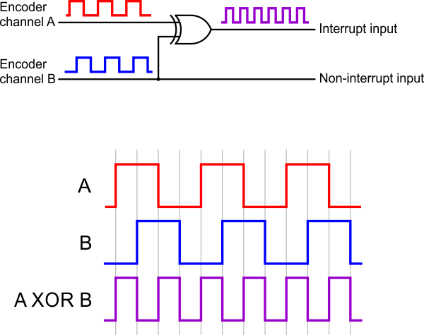 |
The XORed signal and the channel B signal can be used to reconstruct the channel A signal by simply XORing them again: (A XOR B) XOR B = A. For both encoders, channel A leads channel B when the motor is rotating in the forward direction; that is, A rises before B rises and A falls before B falls. (The waveforms in the diagram above would be produced by forward rotation.)
The Zumo 32U4 library provides appropriate interrupt service routines and functions for reading the encoders and keeping track of their counts (see Section 6).
Related products


Home | Forum | Blog | Support | Ordering Information | Lists | Distributors | BIG Order Form | About | Contact
© 2001–2026 Pololu Corporation
