Support » Tic Stepper Motor Controller User’s Guide » 4. Setting up the controller »
4.7. Setting up RC position control
This section explains how to set up the Tic to read a hobby RC servo signal and use that signal to control the position of the stepper motor.
In this mode, the Tic will behave somewhat like an RC servo. One advantage of the Tic is that you can set up the range of motion of your system to be very large (e.g. tens of turns) or very small (e.g. a few degrees). One important difference between the Tic and an RC servo is that the Tic does not receive any kind of feedback from the stepper motor about its position. When you power on an RC servo and send it a signal, it immediately moves to the position corresponding to that signal. When you power on the Tic, it does not know what position the stepper motor is in, so it will wait for a valid RC signal, and then assume that the stepper motor is already at the position that corresponds to that signal. Also, there are other error conditions besides losing power that will cause the Tic to become uncertain about its current position and re-learn it when the system returns to normal (see Section 5.4).
If you have not done so already, you should follow the instructions in Section 4.3 to configure and test your stepper motor. Next, with the system unpowered, connect your RC receiver to the Tic’s GND, 5V, and RC pins as shown in the diagram below.
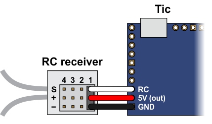 |
In this configuration, the RC receiver will be powered by the Tic’s 5 V regulator via the 5V output pin. If you want to power the receiver from another power source instead, you should not connect the Tic’s 5V pin to it as doing so would short the two sources together and could damage the Tic or receiver.
If the Tic gets reset when you plug in your RC receiver, it might be because the in-rush current of the receiver is too much for the Tic’s 5V line and causes its voltage to drop temporarily. As general good engineering practice, we recommend making and breaking electrical connections only while your devices are powered off.
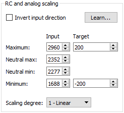 |
Example Tic scaling settings for RC position control mode. |
|---|
Now connect the Tic to your computer via USB. In the Tic Control Center software, set the Tic’s control mode to “RC position” and click “Apply settings”. In the “Scaling” box, click “Learn…” to start the Input Setup Wizard. The wizard will help you measure the neutral, maximum, and minimum positions of your RC signal. When the wizard is finished, it will set five of the input scaling parameters (input maximum, input neutral max, input neutral min, input minimum, and invert input direction) appropriately so that the neutral RC signal gets mapped to a position of 0, the maximum RC signal gets mapped to the target maximum, and the minimum RC signal gets mapped to the target minimum. If you have previously changed the target maximum and target minimum, you should set them back to their default values of 200 and -200, respectively. Click “Apply settings” to save these settings to the Tic.
Now connect motor power and click “Resume” to start your system. If you move your input from the neutral position to the maximum position, you should see the motor move by 200 steps. If you move your input from the neutral position to the minimum position, you should see the motor move by 200 steps in the other direction.
You should make sure that the motor is moving in the correct direction. If it is not, you can check the “Invert motor direction” checkbox to fix it. (You could also rewire the stepper motor to reverse the current in one coil, but be sure to turn off the stepper motor power before doing that.)
Next, you should set the target maximum and minimum parameters in the “Scaling” box to set the range of motion of your system. The target maximum must be zero or more, and the target minimum must zero or less. These numbers correspond to microsteps if you have enabled microstepping.
Finally, check the “Scaling degree” parameter. The default setting is “1 – Linear”. If you want finer control near the neutral point of your input and coarser control near the ends, you can change it to one of the higher settings.
For details about what kind of RC signals the Tic can accept, and how the input scaling works, see Section 5.2.
Related products


Related categories


Home | Forum | Blog | Support | Ordering Information | Lists | Distributors | BIG Order Form | About | Contact
© 2001–2026 Pololu Corporation
