Support » Tic Stepper Motor Controller User’s Guide » 5. Details »
5.4. Error handling
This section explains the details of how the Tic detects and handles error conditions. The table below summarizes the Tic’s error handling:
| Operation state | Conditions | Effects |
|---|---|---|
| Reset | ||
| De-energized | ||
| Soft error | ||
| Waiting for ERR line | ||
| Starting up | ||
| Normal |
|
The Tic constantly evaluates the conditions listed above to see if they are happening or not. The detailed definitions of these conditions are explained below. If a condition is happening, the Tic will go into the corresponding operation state as shown in the table above. If multiple conditions are happening, the Tic will choose the first state (the highest state in the table above) that has an active condition. If no conditions are happening, the Tic will proceed with normal operation. After the Tic determines what operation state it is in, it performs the corresponding effects for that operation state as listed in the table. These effects are explained in detail below.
Error handling variables
The “Operation state” variable says what operation state the Tic is currently in. The “Error status” variable says what error conditions are currently happening: it has bits for most of the conditions in the table above. The “Errors occurred” variable helps detect errors that only occur for a brief period of time: it contains bits that get set whenever an error happens, and can be cleared with a command. These variables can be read over TTL serial, I²C, or USB. For more information about these variables, see Section 7.
Condition: Motor driver error
A motor driver error means that the motor driver IC on the Tic has detected a problem and reported it to the main microcontroller.
When the Tic detects a motor driver error, it latches the error, meaning that the “Motor driver error” bit in the “Error status” variable will stay set even after the motor driver stops signalling the fault condition. By default, the Tic will clear the latched error every 0.5 s, but you can disable this behavior by unchecking the “Automatically clear driver errors” checkbox in the Tic Control Center. The Tic will also clear the latched error whenever it receives a “Clear driver error” command.
The MP6500 motor driver IC on the Tic T500 reports motor driver errors due to over-current, over-temperature, and over-voltage conditions.
The DRV8825 motor driver IC on the Tic T825 reports motor driver errors due to over-current and over-temperature conditions.
The DRV8834 motor driver IC on the Tic T834 reports motor driver errors due to over-current, over-temperature, and under-voltage conditions.
The TB67S249FTG motor driver IC on the Tic T249 reports motor driver errors due to over-current, over-temperature, and open-load conditions. However, the Tic ignores the open-load fault because it happens frequently during normal operation.
The DRV8711 gate driver IC on the Tic 36v4 reports motor driver errors due to over-current, over-temperature, under-voltage, and predriver fault conditions. In addition, the Tic regularly checks that the DRV8711’s register settings are correct and will report an error if verification fails.
When the Tic T249 or Tic 36v4 detects a motor driver error, it reports the type of error. This information can be read via serial, USB, and I²C using the “Get variable” command, and is displayed in the “Status” tab of the Tic Control Center. This feature is not available on the other Tics.
In response to a motor driver error, the Tic will go into the Reset state and assert the motor driver’s reset line. In many cases, resetting the motor driver causes it to stop reporting the error. The Tic latches the motor driver error so that it can avoid immediately going back to its previous state when the driver stops reporting the error and causing a fast oscillation between states.
Motor driver errors are ignored during the brief time when the coil current is stabilizing because the Tic T834 reports a motor driver error for a few milliseconds after coming out of its Reset state. The Tic needs to ignore that error so it can successfully enable the motor the driver and not go back into the Reset state.
Tic 36v4 warning: The Tic 36v4 has no meaningful over-temperature shut-off (while the gate driver IC has over-temperature protection, it is the external MOSFETs that will overheat first). An over-temperature condition can cause permanent damage to the motor driver. We strongly recommend you do not increase the current limit setting beyond 4000 mA (or lower in applications with reduced heat dissipation) unless you can first confirm that the temperature of the MOSFETs will stay under 140°C.
Condition: Low VIN
The “Low VIN” error indicates that the voltage on VIN has dropped well below the minimum operating voltage, as shown in this table.
| Tic T834 | Tic T500 | Tic T249 | Tic 36v4 | Tic T825 | |
|---|---|---|---|---|---|
| Minimum operating voltage: | 2.5 V | 4.5 V | 10 V | 8 V | 8.5 V |
| Low VIN threshold: | 2.1 V | 3.0 V | 5.5 V | 5.8 V | 7.0 V |
Condition: Intentionally de-energized
The “Intentionally de-energized” error bit is 0 when the Tic starts up. It can be set with the “De-energize” command and cleared with the “Energize” command. Those two commands are used to implement the “De-energize” and “Resume” buttons in the Tic Control Center (the “Resume” button also issues an “Exit safe start” command).
You can use those commands over serial, I²C, or USB to turn off your motor and reduce power consumption. However, note that if you do this, then the “De-energize” button in the Tic Control Center will not be as useful because its effect will get undone when your device issues an “Energize” command.
Condition: Kill switch active
The “Kill switch active” error indicates that one of the pins configured as a kill switch is in its active state. For more information about kill switches, see Section 5.5.
Condition: Required input invalid
This error indicates that the Tic’s main input signal is not valid, so it cannot be used to set the target position or velocity. This error currently only happens in RC control modes.
Condition: Serial error
This error indicates that something went wrong with the I²C or TTL serial communication. When the control mode is “Serial / I²C / USB”, this bit gets set whenever any of the following conditions happen:
- The Tic receives an invalid command byte or data byte over I²C or TTL serial. (This also causes the “Serial format” bit in the “Errors occurred” variable to be set.)
- The Tic receives a TTL serial byte with its most significant bit set (which starts a new command) while it is still waiting for data bytes from the previous command. (This also causes the “Serial format” bit in the “Errors occurred” variable to be set.)
- The Tic receives an incorrect CRC byte at the end of a command. (This also causes the “Serial CRC” bit in the “Errors occurred” variable to be set.)
- The Tic receives a TTL serial byte at a time when its hardware or software buffers are not able to hold the byte, and the byte is lost. (This also causes the “Serial RX overrun” bit in the “Errors occurred” variable to be set.) This should not happen under normal conditions.
- The Tic receives a TTL serial byte that does not have a valid stop bit. (This also causes the “Serial framing” bit in the “Errors occurred” variable to be set.)
In a non-serial control mode, serial errors do not cause the Tic to shut down because the serial error will never get set. However, the serial-related bits in the “Errors occurred” register will still be set, so you can detect serial errors in non-serial control modes.
Starting in firmware version 1.06, the Tic ignores the invalid command bytes 0xFF and 0xFE without triggering an error if they are received via TTL serial. This helps make the Tic less susceptible to noise on its serial lines.
The serial error is cleared whenever the Tic receives any of following commands over serial, I²C, or USB:
- Set target position
- Set target velocity
- Halt and set position
- Halt and hold
- Energize
- Exit safe start
- Reset
Condition: Command timeout
The Tic keeps track of how much time has passed since it last received a serial, I²C, or USB command that is one of the commands that clears the serial error (listed above), or the “Reset command timeout” command. Whenever the Tic’s control mode is “Serial / I²C / USB” and that time exceeds the timeout period, which is one second by default, the Tic sets the “Command timeout” error bit. You can change the timeout period or disable this feature from the “Input and motor settings” tab of the Tic Control Center. When the timeout error occurs, you can clear it by sending one of the commands that clears the serial error (listed above) or by sending the “Reset command timeout” command.
The Tic Control Center sends the “Reset command timeout” command repeatedly while it is connected to a Tic over USB.
The “Command timeout” error is useful if you want to control the Tic over serial, I²C, or USB, and you want to be sure that the stepper motor will stop moving if the device controlling the Tic stops working.
Condition: Safe start violation
The Tic’s safe start feature helps to avoid unexpectedly powering the motor in speed control modes and in “Serial / I²C / USB” mode.
In the “RC speed”, “Analog speed”, or “Encoder speed” control mode, the Tic will generally set the “Safe start violation” error bit whenever the Tic’s “Operation state” is not “Normal” and the “Input after scaling” variable (which represents the target velocity being commanded by the Tic’s main input source) is non-zero. This way, the Tic will never automatically start moving the motor just because all the error conditions have been resolved; it will only start moving the motor if you first put its main input in the neutral position (which maps to a speed of 0), and then move its main input away from the neutral position. If an error happens while you are operating the motor, you will need to move your main input back to the neutral position before you can start moving the motor again.
In the “Serial / I²C / USB” control mode, the Tic will generally set the “Safe start violation” error bit whenever the Tic is not in the normal operation state. You can send an “Exit safe start” command to clear the error for 200 milliseconds, giving the Tic a chance to start up. In general, you should only send the “Exit safe start” command as a direct response to a user action, such as pressing a button. That way, if an error happens and your motor stops, it will only start moving again in response to the user’s action.
You can send the “Enter safe start” command to get back into safe start mode. This command forces the “Safe start violation” bit to be set the next time the Tic evaluates it. After that, the “Safe start violation” bit will only be cleared if the usual conditions for clearing it are satisfied, as described above. In position control modes, where the safe-start feature generally has no effect, this command will cause a temporary “Safe start violation” error that could interrupt movement of the motor.
You can check the “Disable safe start” checkbox in the “Advanced settings” tab of the Tic Control Center to make the “Safe start violation” error never happen, even if an “Enter safe start” command is sent.
The safe-start feature does not do anything useful in the “RC position”, “Analog position”, or “Encoder position” control modes. In those modes, some safety can be provided by the “Learn position” feature as described in the Effect: Learn position section below.
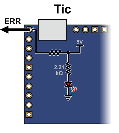
Condition: ERR line high
The Tic reports an “ERR line high” error if it is not driving its ERR pin high and the digital reading on the ERR pin input is high. The error is cleared automatically when either of those conditions stops being true. You can use the “Ignore ERR line high” setting to disable the error.
The Tic uses its ERR pin, which is connected to the red LED, to report errors. Whenever the Tic drives the ERR line high to indicate an error, the red LED turns on. The red LED is in series with a 2.21kΩ resistor. There is a 470Ω resistor with the ERR pin on one side, and the Tic’s microcontroller pin and red LED on the other side.
When there is no error happening, the Tic’s ERR line acts as a digital input so it can detect error signals from other devices. It is pulled low by the LED and a 100 kΩ pull-down resistor. The voltage on the Tic’s microcontroller pin must reach at least 2 V for the input to be guaranteed to read as high.
|
|
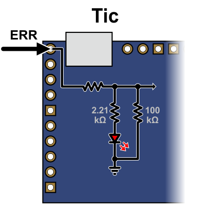
You can connect the ERR lines of multiple Tics together so that when one of the Tics experiences an error and drives its ERR line high, all of the Tics will be notified about the error and shut down. Each Tic you add to the system will load down the ERR lines of the other Tics, so there is a limit to how many Tics you can connect in this way. It should work fine with 5 or fewer Tics. You can probably connect more than that, but at some point, there would be too much load for a single Tic to shut down all of the others. If you want to connect many Tic ERR lines together and find this to be a problem, you could desolder or disconnect the red LED on several of the Tics to reduce that load.
Condition: RC/analog input not ready
The Tic cannot instantly determine the value of its RC or analog inputs: it takes some time for the Tic to get readings and compute averages. In RC and analog control modes, the “RC/analog input not ready” condition prevents the Tic from going into normal operation until its input is ready. This is a temporary condition that should last for at most 500 ms. It only happens right after the Tic starts up, receives a Reset command, or changes its control mode.
Condition: Coil current stabilizing
This condition prevents the Tic from going into normal operation within 10 milliseconds after it changes from the special current limit during error back to the normal current limit, or within 10 milliseconds of resetting the stepper driver.
Effect: De-energize
When the Tic is in the “Reset” or “De-energized” state, it will disable the driver (by driving its ENBL pin high) and stop sending step pulses to the driver. The current flowing through the motor coils will stop.
Effect: Drive ERR line high
When the Tic is experiencing any error (except for the “ERR line high” error), the Tic will drive its ERR line high, which causes its red LED to turn on.
Effect: Reset driver
In the “Reset” operation state, the Tic will reset its stepper motor driver IC. This means that its indexer will be reset to its default position in the table of coil currents.
Effect: Clear encoder count
In the “Reset” state, the Tic constantly sets the “Encoder position” variable, which holds the raw measurement of encoder counts, to 0.
Effect: Soft error response
When the Tic goes from the normal operation state to either the “Soft error” state or the “Waiting for ERR line” state, it will do one of four things depending on how it is configured. You can select one of the following responses from the “Soft error responses” box in the “Advanced settings” tab of the Tic Control Center:
- De-energize: The Tic will de-energize the motor and set the “Position uncertain” flag.
- Halt and hold: The Tic will abruptly stop taking steps, keep the motor energized, and set the “Position uncertain” flag.
- Decelerate to hold: The Tic will set its “Target velocity” to 0, causing the motor to decelerate to a stop and then hold its position. This is the default setting.
- Go to position: The Tic will set its “Target position” to the specified position.
Note that the effects above only happen when the Tic’s “Operation state” changes from “Normal” to “Soft error” or “Waiting for ERR line”. These effects do not happen if there is a soft error right after the Tic starts up, receives a Reset command, or changes its control mode.
You can also set a special current limit to be used while there is a soft error. If enabled, this current limit will be in effect whenever the Tic is in the “Soft error” or “Waiting for ERR line” states, regardless of how it got to those states. To set this current limit, check the “Use different current limit during soft error” checkbox and enter the current limit. The special current limit will only take effect after the Tic stops moving the motor.
Effect: Energize
During normal operation or while it is starting up, the Tic will energize the stepper motor coils by enabling its stepper motor driver.
Effect: Obey input
During normal operation, the Tic sets the stepper motor’s “Target position” or “Target velocity” as specified by its main input.
The motion specified by the main input is held in the “Input state” and “Input after scaling” variables. In the “Serial / I²C / USB” control mode, those variables are set by the “Set target position”, “Set target velocity”, “Halt and hold”, “Halt and set position”, and “Reset” commands, and they do not get reset when an error happens. In other control modes, those variables are set automatically.
Effect: Learn position
When the control mode is “RC position”, “Analog position”, or “Encoder position”, and the Tic starts normal operation, it will check the “Position uncertain” flag. If that flag is set, the Tic will assume that the stepper motor has already reached the position specified by the main input, and so it will set its “Current position” variable equal to the “Target position”, and clear the “Position uncertain” flag.
This means that when you power on your system, or recover from certain errors, the Tic will assume that its position is already correct, and not start moving right away to reach a new position. This feature is similar to the safe start feature described above for the other control modes, because it helps prevent the motor from moving by surprise.
If the Tic’s “Soft error response” is set to “Decelerate to hold” (the default) or “Go to position”, then the “Position uncertain” flag will not be set when the Tic has a soft error, and therefore the Tic will not learn its position when the soft error is resolved, and this could cause unexpected motion. Setting the Tic’s “Soft error response” to “De-energize” or “Halt and hold” makes unexpected motion less likely.
Related products


Related categories


Home | Forum | Blog | Support | Ordering Information | Lists | Distributors | BIG Order Form | About | Contact
© 2001–2026 Pololu Corporation
