Support » Tic Stepper Motor Controller User’s Guide » 5. Details »
5.5. Pin configuration
This section explains how to configure the control pins of the Tic: SCL, SDA/AN, TX, RX, and RC.
The settings for these pins are found in the “Pin configuration” section of the “Advanced settings” tab in the Tic Control Center, as shown below:
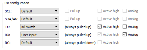 |
Example pin configuration settings for a Tic Stepper Motor Controller. |
|---|
To the right of each pin name is a drop-down box where you can assign a function to the pin. Each pin function is documented below.
Pin function: Default
By default, each pin’s function is set to “Default”. This means that the Tic will automatically choose the pin’s function and choose the related options (Pull-up, Active high, Analog) based on the “Control mode”, as shown in the table below.
| Control mode | RC position, RC speed, Serial / I²C / USB, or STEP/DIR |
Analog position, Analog speed |
Encoder position, Encoder speed |
|---|---|---|---|
| Default function for SCL | Serial (SCL), pull-up enabled | Potentiometer power | Serial (SCL), pull-up enabled |
| Default function for SDA/AN | Serial (SDA), pull-up enabled | User input, analog enabled | Serial (SDA), pull-up enabled |
| Default function for TX | Serial (TX) | Serial (TX) | Encoder input |
| Default function for RX | Serial (RX) | Serial (RX) | Encoder input |
| Default function for RC | RC input | RC input | RC input |
Note that the TX and RX pins are always pulled up, and the RC pin is always pulled down.
When a pin’s function is “Default”, the Tic Control Center disables the checkboxes for the Pull-up, Active high, and Analog options because they will have no effect. However, the states of those checkboxes will still be saved to the Tic.
Pin function: User input
A pin with the “User input” function is used as a digital and/or analog input. You can read the state of the input using the “Get variable” command or by running ticcmd --status --full. See the Variable reference section for more information about the user input variables.
Pin function: User I/O
For now, the “User I/O” function is exactly the same as “User input”. (In the future, we might add commands allowing you to turn User I/O pins into outputs and drive them high or low.) This function is only available for the SCL, SDA, TX, and RX pins. The RC pin cannot be an output due to hardware limitations.
Pin function: Potentiometer power
A pin with the “Potentiometer power” function drives high so that it can be used to power a potentiometer for the Tic’s analog input. This function is only available for the SCL pin.
Pin function: Serial
A pin with the “Serial” function acts as the TTL serial or I²C pin as described by its name. This function is only available for the SCL, SDA, TX, and RX pins. It is possible to enable the RX pin as a serial pin without enabling TX if you just want to send commands to the Tic without reading anything back. (It is also possible to enable TX as a serial pin without enabling RX, but this is not useful since the Tic only sends data on TX in response to commands received on RX.) It is not possible to enable the SCL or SDA pin as a serial pin without enabling both, so the Tic Control Center will warn you and offer to fix your settings if try to do that.
Pin function: RC input
A pin with the “RC input” function is used to measure incoming RC pulses. This function is only available on the RC pin, and configuring the RC pin as a “User input” actually has the same effect because the Tic’s RC pulse measuring system is always active, regardless of what the RC pin is actually being used for.
Pin function: Encoder input
A pin with the “encoder input” function is used to read signals from a quadrature encoder. This function is only available on the TX and RX pins, and it is actually the same as “User input” on these pins because the Tic’s encoder reading system is always active, regardless of what the TX and RX pins are actually being used for.
Pin function: Kill switch
A pin with the “Kill switch” function is used as a digital input that can tell the Tic to stop moving the motor. If the “Active high” checkbox is checked, that means that the kill switch is considered active whenever its digital reading is high (5 V). If the “Active high” checkbox is not checked, the switch is considered active whenever its digital reading is low (0 V). The Tic sets its “Kill switch active” error bit whenever any of the pins configured as kill switches are in their active state, and it clears the bit once all of the kill switches have left the active state.
As described in Section 5.4, the kill switch error is considered to be a “Soft error”. By default, the Tic will decelerate to zero speed and hold position when a kill switch is triggered, but you can change this behavior using the “Soft error response” setting.
Pin function: Limit switch forward/reverse
A pin with the “Limit switch forward” function is used as a digital input that can tell the Tic to prevent the motor from going in the forward direction. Similarly a pin with the “Limit switch forward” function can tell the Tic to prevent the motor from going in the reverse direction. The “Active high” checkbox controls the polarity of the limit switch input.
If a limit switch is active while the motor is moving in the direction limited by the switch, the Tic abruptly halts motor movement and sets the “Position uncertain” flag.
See Section 4.14 for information about setting up limit switches.
Pin option: Pull-up
The “Pull-up” checkbox allows you to enable the internal pull-up resistor for a pin. This option is only available for the SCL and SDA pins. The TX and RX pins are always pulled up with 100 kΩ resistors which cannot be disabled. The RC pin input is always pulled down.
If the “Pull-up” checkbox is disabled (grayed out), it means that the value of the checkbox will have no effect on the Tic, either because the pin function is “Default”, so the pull-up option is based on the control mode of the device as described above, or because a pin function is selected that never uses pull-ups (e.g. potentiometer power).
Pin option: Active high
For pins configured as kill switch inputs, the “Active high” checkbox lets you choose whether the switch is active when the digital reading is high (checked) or low (unchecked).
If the “Active high” checkbox is disabled (grayed out), it means that the value of the checkbox will have no effect on the Tic because the pin’s function is not set to “Kill switch”.
Pin option: Analog
The “Analog” checkbox tells the Tic to do analog readings on the specified pin. The RC pin is not capable of doing analog readings due to hardware limitations.
If the “Analog” checkbox is disabled (grayed out), it means that the value of the checkbox will have no effect on the Tic because the pin function is “Default”. In that case, the analog option is based on the control mode of the device as described above.
You can read the state of the analog inputs using the “Get variable” command. See the Variable reference section for more information about the analog reading variables.
Because the SDA/AN pin is used to control the speed or position of the stepper motor in the “Analog position” and “Analog speed” modes, it gets special treatment whenever its analog input is enabled. For the SDA/AN pin, the Tic averages together eight 10-bit ADC readings, whereas the Tic just does a single 10-bit ADC reading at a time for the other pins.
Related products


Related categories


Home | Forum | Blog | Support | Ordering Information | Lists | Distributors | BIG Order Form | About | Contact
© 2001–2026 Pololu Corporation
