Support » Tic Stepper Motor Controller User’s Guide » 4. Setting up the controller »
4.14. Setting up limit switches and homing
This section explains how to set up limit switches and homing. Limit switches can help prevent your system from leaving its desired range of motion. The homing feature enables the Tic to use a limit switch as a reference to determine the position of the motor. The homing feature requires at least one limit switch, but you can use limit switches without using homing.
To use limit switches, you should first make sure that you have version 1.7.0 or later of the Tic configuration software. You can see the software version number in the Tic Control Center by opening the “Help” menu and selecting “About”. (On macOS, “About” is in the “Pololu Tic Control Center” menu instead.) You can get the latest software from Section 3. You will also need to make sure your Tic has firmware version 1.06 or later. The firmware version is displayed in the “Status” tab of the Tic Control Center. If you have an earlier version of the firmware, see Section 5.7 for upgrade instructions.
Any of the Tic control pins (SCL, SDA, TX, RX, or RC) can be configured as a digital input for a limit switch.
To set up a limit switch, you should go the “Advanced settings” tab and set the function of a pin to “Limit switch forward” or “Limit switch reverse”. A forward limit switch prevents the motor from going in the forward direction (increasing position, positive velocity), and a reverse limit switch prevents the motor from going in the reverse direction. The “Active high” checkbox controls the polarity of the limit switch input. If “Active high” is checked, then motor movement will be limited when the voltage on the pin is high (5 V). If it is not checked, then the motor movement will be limited when voltage on the pin is low (0 V). The “Analog” pin configuration checkbox does not affect the limit switch or homing functionality. It is OK to configure multiple pins to be the same type of limit switch.
We generally recommend using a fail-safe configuration; if the limit switch somehow becomes disconnected from the Tic, then the Tic should treat the limit switch as if it were active. To achieve a fail-safe limit switch configuration on the Tic’s SCL or SDA pins, check the pin’s “Pull-up” checkbox and its “Active high” checkbox, so that the Tic will pull the line high and consider high to be the active state of the limit switch. To achieve a fail-safe configuration on the TX or RX pins, both of which are always pulled up, check the pin’s “Active high” checkbox. To achieve a fail-safe configuration on the Tic’s RC pin, leave the “Active high” checkbox unchecked.
Once you have configured your limit switch, click the “Apply settings” button. If you are using a fail-safe configuration and have not yet connected the limit switch, the Tic should report that the limit switch is active. You should check that this is the case by looking in the “Status” tab of the Tic Control Center. Find the “Limit switches active” field and make sure it indicates that your limit switch is active. Depending on whether the forward or reverse limit switches are active, this field will either say “Forward”, “Reverse”, or “Both”.
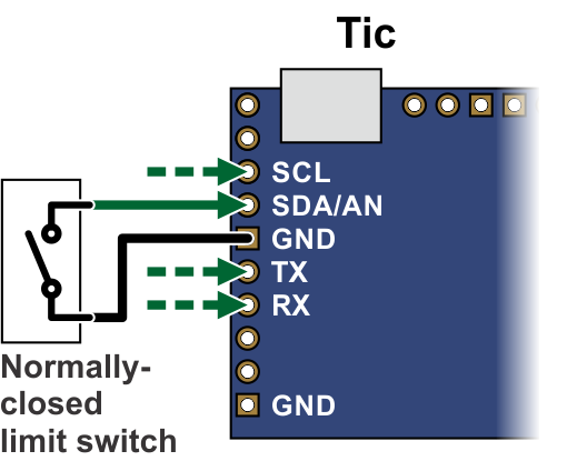
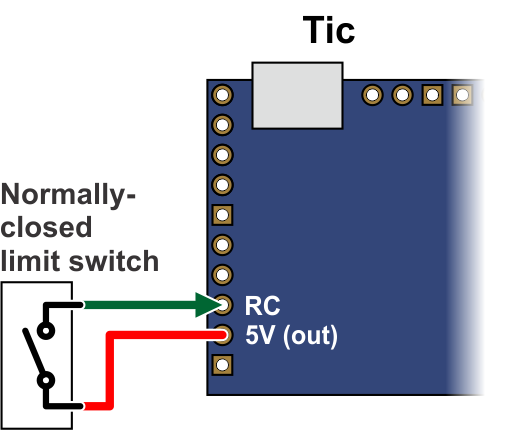
Next, disconnect the Tic from all power sources, including USB, and connect your limit switches. If you are using a fail-safe configuration, you will need to use two contacts of the switch that are normally closed (NC), meaning that electricity conducts between the two contacts when the switch is not activated. You should connect one of the switch contacts to the Tic’s configured limit switch pin, and connect the other switch contact to either GND or 5V, whichever is the opposite of the pin’s default state. This is shown in the diagrams below:
|
|
Once you have configured and connected the limit switches, you can test them. Connect the Tic to USB and activate the limit switches (e.g. press them with your hands) while looking at the “Limit switches active” field in the “Status” tab. By default, it should say “None”. When you activate a limit switch, the field should indicate which limit switch direction has been activated.
Next, you can reconnect the stepper motor power and try controlling the motor. Make sure that reverse movement (negative speed, decreasing position) causes movement towards the reverse limit switch if you have one. Make sure that forward movement (positive speed, increasing position) causes movement towards the forward limit switch if you have one.
If appropriate for your system, we recommend further testing: make sure that the motor stops properly when it hits a limit switch, and make sure you can continue operation by driving it away from the limit switch. If the control mode you are using does not allow the stepper motor to hit the limit switches, you might consider temporarily changing the control mode to “Serial / I²C / USB” so you can control the motor manually using the “Set target” interface at the bottom of the “Status” tab.
Setting up homing
The Tic can perform a homing procedure that uses a limit switch as a position reference.
To test this feature, you can open the “Device” menu in the Tic Control Center and use the “Go home reverse” or “Go home forward” command. The “Go home reverse” command moves the motor in reverse until a reverse limit switch activates, and then backs up until the limit switch deactivates. The “Go home forward” command moves the motor forward until a forward limit switch activates, and then backs up until the limit switch deactivates. The Tic Control Center software disables these commands if you have not configured limit switches in the corresponding directions. At the end of the homing procedure, after the limit switch deactivates, the Tic sets its current position to 0 and resumes normal operation. These menu options use the “Go home” command, which is supported over USB, serial, and I²C, and documented in Section 8.
During the homing procedure, the speed of the motor is controlled by the “Homing speed towards” and “Homing speed away” settings in the “Advanced settings” tab. The “Homing speed towards” setting controls the speed that the Tic uses while traveling towards the limit switch, while the “Home speed away” setting controls the speed that the Tic uses briefly while traveling away from the limit switch to deactivate it.
If you are using the “RC position”, “Analog position”, or “Encoder position” control modes, you might want to enable automatic homing so that you do not have to send the “Go home” command to the Tic. If you check the “Enable automatic homing” checkbox in the “Advanced settings” tab, the Tic will perform the homing procedure whenever it is being commanded to go to a specific position but it is uncertain about is current position (e.g. immediately after motor power is applied). The “Automatic homing direction” setting lets you choose whether the automatic homing will drive the motor in the reverse or forward direction.
Related products


Related categories


Home | Forum | Blog | Support | Ordering Information | Lists | Distributors | BIG Order Form | About | Contact
© 2001–2026 Pololu Corporation
