Support » Tic Stepper Motor Controller User’s Guide » 5. Details »
5.2. Analog/RC input handling
This section documents the details of how the Tic reads its analog and RC inputs and how it averages, filters, and scales those inputs in order to set a target velocity or target position.
Analog readings on the SDA pin
When the SDA pin is configured as an analog input, the Tic regularly uses its 10-bit ADC to take readings of the voltage on the pin. After it completes 8 ADC readings, it adds the readings together and multiplies by 8 to get a number between 0 and 65,472 which it stores in the “Analog reading SDA” variable. The “Analog reading SDA” variable, like most of the variables in this section, can be read from the Tic over USB, serial, or I²C, and is listed in Section 7.
Pulse measurement on the RC pin
The Tic measures the width of RC pulses on its RC input pin. The signal on the RC pin should look like the waveform shown below:
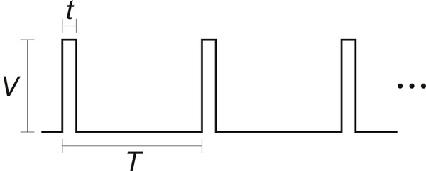 |
The signal should be low (0 V) normally and have periodic pulses with an amplitude (V) of at least 2 V. The width of the pulses (t) should be between 200 µs and 2700 µs. The period of the signal (T), should be at most 100 ms, and the there is no particular lower limit. When the Tic has received three good pulses in a row, it writes the width of the latest pulse to the “RC pulse width” variable in units of 1/12 µs.
If the Tic goes more than 100 ms without receiving a good pulse, it will change the “RC pulse width” variable to 0xFFFF (65,535) to indicate that the RC signal has been lost. Furthermore, if the Tic goes more than 500 ms without receiving three good pulses in a row, it will change the “RC pulse width” variable to 0xFFFF to indicate the RC signal is unreliable.
Input averaging
The Tic’s input averaging feature, which is enabled by default, helps smooth out noisy RC or analog input signals by taking a running average.
By default, when the Tic’s control mode is set to any of the RC or analog options, the Tic calculates a running average of the last four readings (from the “Analog reading SDA” or “RC pulse width” variables) and stores that average (possibly scaled by a power of two) in the “Input after averaging” variable. If you disable input averaging by unchecking the “Enable input averaging” checkbox in the Tic Control Center, then the “Input after averaging” variable is set directly from the corresponding input variable without averaging.
Input hysteresis
Another optional feature that helps deal with noisy inputs is input hysteresis. The input hysteresis feature can be useful if you are using a noisy input to set the position of a stepper motor, and you want the stepper motor to be at rest whenever you are not changing the input, instead of moving around by small amounts and making noise.
This feature is turned off by default, but can be turned on by entering a value of 2 or more into the “Input hysteresis” setting in the “Input conditioning” box of Tic Control Center. When the hysteresis value is 2 or more, the Tic essentially takes the “Input after averaging” variable and maps it to the nearest number that is a multiple of the “Input hysteresis” value. However, it does this mapping with hysteresis; the result of this process, which is stored in the “Input after hysteresis” variable, only changes if the input is at least one hysteresis value away from the current result.
For example, suppose your hysteresis value is 100, and your “Input after averaging” starts out at 670. The initial “Input after hysteresis” value will be 600 (it always rounds down initially; afterward, it always rounds toward the current “Input after hysteresis” value). The “Input after hysteresis” will change to 500 if the “Input after averaging” drops to a value between 401 and 500, and it will change to 700 if the “Input after averaging” rises to a value between 700 and 799. If the “Input after averaging” remains between 501 and 699, the “Input after hysteresis” will not change.
When the input hysteresis feature is disabled, the “Input after hysteresis” variable is just a copy of “Input after averaging”.
One way to choose a good hysteresis value would be look at the “Input after averaging” variable that is displayed in the Tic Control Center, see how much it varies when you are not moving the input, and set the hysteresis value to something larger than that.
Input before scaling
The Tic’s input scaling routine requires a number between 0 and 4095, but the “Input after hysteresis” variable might be more than that. The “Input after hysteresis” variable is divided by a power of two to make a variable called “Input before scaling” that is between 0 and 4095.
The “Input before scaling” variable cannot be directly read from the Tic but it can be computed from the “Input after hysteresis” variable using the units table below. For example, if you are in an analog control mode with input averaging enabled, you can get the “Input before scaling” by reading the “Input after hysteresis” variable and dividing by 8. If you are in an analog control mode without input averaging enabled, you would only divide by 2. If you are in an RC control mode, you would divide by 8.
Input variable units
The table below specifies the units of the input variables defined above. In analog mode, the units are specified by how many bits the reading has. For example, a 12-bit reading would be a number between 0 to 4095, where 0 represents 0 V and 4095 represents the Tic’s logic voltage (the voltage on the 5V pin).
| Control mode | Input averaging enabled | Input after averaging, Input after hysteresis, Input hysteresis |
Input before scaling |
|---|---|---|---|
| Analog | Yes | 15-bit | 12-bit |
| Analog | No | 13-bit | 12-bit |
| RC | Yes | 1/12 µs | 2/3 µs |
| RC | No | 1/12 µs | 2/3 µs |
RC and analog scaling
The settings in the “RC and analog scaling” box of the Tic Control Center determine how the “Input before scaling” variable gets mapped to a signed 32-bit integer that will either be used as a target position or a target velocity depending on the Tic’s control mode. For tips about how to set up these settings when you are getting started with the controller, see the section for your control mode under Section 4.
The graphs below illustrate how input values are mapped to target values:
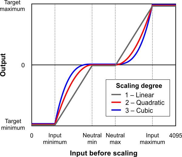 |
This graph shows how the Tic’s RC/analog input is scaled to produce a target position or target velocity (input direction not inverted). |
|---|
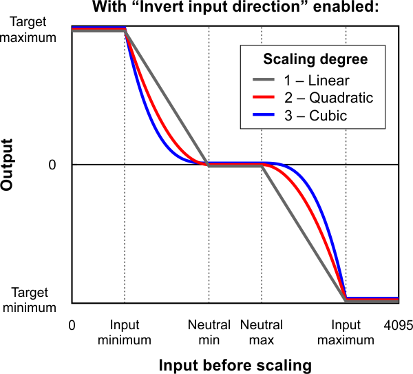 |
This graph shows how the Tic’s RC/analog input is scaled to produce a target position or target velocity (input direction inverted). |
|---|
When the “Invert input direction” checkbox is not checked, the input values are mapped to output/target values according to these rules:
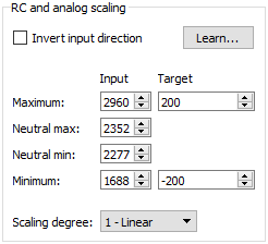 |
Example Tic scaling settings for RC position control mode. |
|---|
- Any input value greater than the input maximum gets mapped to the target maximum.
- Any input value between the input neutral max and the input maximum gets mapped to a number between 0 and the target maximum.
- Any input value between the input neutral min and input neutral max gets mapped to 0.
- Any input value between the input minimum and input neutral min gets mapped to a number between the target minimum and 0.
- Any input value less than the input minimum gets mapped to the target minimum.
When the “Invert input direction” checkbox is checked, it changes the scaling so that higher input values correspond to lower target values. You can think of it as simply switching the target maximum and target minimum in the rules above.
The scaling degree can be set to “1 – Linear”, “2 – Quadratic”, or “3 – Cubic”. With the default setting of “1 – Linear”, the scaling function is linear. If you choose a higher scaling degree, then the Tic uses a higher-degree polynomial function, which can give you finer control when the input is closer to its neutral position. With linear scaling, if the input is one quarter (1/4) of the way from the input neutral max to the input maximum, the target will be one quarter (1/4) of the target maximum. With quadratic scaling, the output would be one sixteenth (1/16) of the target maximum. With cubic scaling, the output would be one sixty fourth (1/64) of the target maximum.
The input maximum, input neutral max, input neutral min, and input minimum must be between 0 and 4095. The target maximum must be between 0 and +2,147,483,647, while the target minimum must be between 0 and -2,147,483,647.
Analog/RC input state
When the Tic’s control mode is analog or RC, the Tic’s “Input state” variable starts off in the “not ready” state when the Tic starts running and has not yet collected its first set of analog readings or detected the RC signal. The Tic leaves this state quickly (usually within 100 ms). After that, the Tic’s input state will be in “invalid” if its RC input signal is missing or bad. There is currently no concept of an analog signal being invalid, so the analog control modes do not use that state. If the analog/RC input is valid, then the input state variable will either be “Target position” or “Target velocity” depending on what control mode was selected. This indicates that the Tic has successfully read its input and populated the “Input after scaling” variable with either a target position or a target velocity. For details about how the “Input state” variable is encoded, see Section 7.
Related products


Related categories


Home | Forum | Blog | Support | Ordering Information | Lists | Distributors | BIG Order Form | About | Contact
© 2001–2026 Pololu Corporation
